EP0899577A2 - Imagerie par résonance magnétique - Google Patents
Imagerie par résonance magnétique Download PDFInfo
- Publication number
- EP0899577A2 EP0899577A2 EP98305773A EP98305773A EP0899577A2 EP 0899577 A2 EP0899577 A2 EP 0899577A2 EP 98305773 A EP98305773 A EP 98305773A EP 98305773 A EP98305773 A EP 98305773A EP 0899577 A2 EP0899577 A2 EP 0899577A2
- Authority
- EP
- European Patent Office
- Prior art keywords
- image
- projection
- magnetic resonance
- resonance imaging
- slab
- Prior art date
- Legal status (The legal status is an assumption and is not a legal conclusion. Google has not performed a legal analysis and makes no representation as to the accuracy of the status listed.)
- Withdrawn
Links
Images


Classifications
-
- G—PHYSICS
- G01—MEASURING; TESTING
- G01R—MEASURING ELECTRIC VARIABLES; MEASURING MAGNETIC VARIABLES
- G01R33/00—Arrangements or instruments for measuring magnetic variables
- G01R33/20—Arrangements or instruments for measuring magnetic variables involving magnetic resonance
- G01R33/44—Arrangements or instruments for measuring magnetic variables involving magnetic resonance using nuclear magnetic resonance [NMR]
- G01R33/48—NMR imaging systems
- G01R33/483—NMR imaging systems with selection of signals or spectra from particular regions of the volume, e.g. in vivo spectroscopy
- G01R33/4833—NMR imaging systems with selection of signals or spectra from particular regions of the volume, e.g. in vivo spectroscopy using spatially selective excitation of the volume of interest, e.g. selecting non-orthogonal or inclined slices
- G01R33/4835—NMR imaging systems with selection of signals or spectra from particular regions of the volume, e.g. in vivo spectroscopy using spatially selective excitation of the volume of interest, e.g. selecting non-orthogonal or inclined slices of multiple slices
Definitions
- the present invention relates to magnetic resonance imaging.
- MRA Magnetic Resonance Angiography
- MIP Maximum Intensity Processing
- CT computer tomography
- MRI magnetic resonance imaging
- Projection images are especially useful for screening vascular morphology and pathological diseases, such as stenosis, atherosclerosis and aneurysm.
- radiologists preferably view projection images rather than MRI slice images.
- a MIP image is essentially a projection of a three-dimensional (3D) volume from a designated viewing point. The brightest pixel along each specified path from the view is picked to form the projection image.
- MIP images can be acquired from different viewing points, providing radiologists with flexibility to study cases.
- the user also defines an area of interest. The tissues outside this area are excluded in the MIP process and therefore do not contribute to the finally formed MIP images. This improves the quality of the projection images. Because all the imaging data is always available, the user may also change the definition of the area of interest, if desired.
- MRA MIP images are created after all axial (original) images are acquired. That is, only after the whole imaging process is completely accomplished, can the MIP process be initiated.
- the scanning process and MIP process are performed sequentially. It takes approximately 7-15 minutes to acquire image data during the initial data acquisition or scanning step.
- the MIP processing is performed after all of the image data has been acquired. Thus, from the start of scanning, approximately 15-20 minutes elapse before a radiologist can view the MRA MIP images and render a diagnosis. If the resulting MIP images are not of sufficient quality to permit a diagnosis due to, e.g. improper scanning parameters or incorrect volume coverage etc., an additional 15-20 minutes must be expended in order to repeat the process.
- MRA Magnetic resonance Imaging
- MIP images are different to axial images, and there is no explicit information to indicate the relative position of axial images relative to the MIP images.
- the data acquisition step can not be interrupted in order to start a new imaging step.
- the only option available is to complete the present data acquisition phase and then repeat the entire scan procedure with modified parameters.
- a magnetic resonance imaging method Magnetic flux is produced in the examination region. Dipoles in the examination region are induced to a resonance, generating radio frequency resonance signals. At least phase and read magnetic field gradient pulses are generated in orthogonal directions across the examination region. The radio frequency magnetic resonance signals are received and demodulated. Image representations are reconstructed from the received and demodulated magnetic resonance signals.
- a projection image in a sliding interleaved 3D acquisition mode is updated at a rate substantially equal to a rate of growing a projection image in a contiguous 2D stack acquisition mode of a parallel interactive slicing projection technique. The updated projection image is displayed for use in clinical diagnosis.
- a magnetic resonance imaging system includes means for generating a magnetic field in an examination region, a radio frequency pulse controller and transmitter for inducing dipoles in the examination region to resonance such that radio frequency resonance signals are generated, gradient magnetic field coils and a gradient magnetic field controller for generating at least phase and read magnetic field gradient pulses in orthogonal directions across the examination region, a receiver for receiving and demodulating the radio frequency magnetic resonance signals, and an image processor for reconstructing image representations.
- the image processor includes means for updating a projection image in a sliding interleaved 3D acquisition mode at a rate substantially equal to a rate of growing a projection image in a contiguous 2D stack acquisition mode of a parallel interactive slicing projection technique, and means for displaying said updating projection image for use in clinical diagnosis.
- a temporally building MIP image 10 is formed and displayed while the scanning is ongoing.
- the temporally building MIP image 10 permits a radiologist simultaneously to track if image quality is good enough for clinical diagnosis, if the prescribed positioning for volume coverage is correct, and if the anatomical morphology of interest is covered.
- the radiologist can stop the scanning either to restart or do image processing/analysis as soon as the interested volume coverage is achieved. In the latter case, the whole imaging process can be shortened to save scanner time, increase patient convenience, and increase throughput.
- this technique can still ensure a complete coverage without wasting unnecessary patient imaging time due to oversampling of more slices.
- each reconstructed slice is projected 14 to generate the next line of the projection image 10 .
- the update or growing rate of the temporary MIP image 10 depends on the imaging speed and acquisition fashion. In the case of a contiguous 2D stack acquisition mode (described further below), the data acquisition speed is approximately 5-10 seconds per slice, while in the case of a 3D multiple volumes/slabs acquisition mode, the imaging speed is around 60-90 seconds for 9-12 slices. Thus, the on-line MIP image 10 grows at a rate of 5-10 seconds per image line with 2D scanning, and 60-90 seconds per 9-12 image lines for 3D scanning.
- the MIP image 10 is formed from a group or a contiguous stack of 2D multi-slice images (axial) 22 which are generated in the data acquisition process 12 and then stored in a memory 24 .
- the imaging time is in the range of 5-8 seconds, depending on the scanning parameters of T R and N Y .
- the parallel interactive slicing MIP (maximum intensity processing) technique of the present invention is not applicable.
- the parallel interactive slicing MIP technique improves performance, particularly on the number of slices in each volume (slab) 26 . With only few slabs the updating speed of the MIP images 30 is rather slow.
- N Z the total slices in a volume 26
- N B the blanked slices at the edge of volume 26 due to, e.g. RF imperfection.
- MIP image growth rate is much slower and not continuous. This is simply because prior to the image reconstruction step, all data (phase encodings) in a volume must be collected in the memory.
- a data acquisition and a reconstruction process 32 resonance is excited in a first volume or slab and the data collected to collect the data lines of a first of the volumes 26 .
- the very edge data lines e.g. the edge 5%, are discarded.
- a projection processor 34 projects the first 90% of the slices of the first volume to form the first several data lines of the projection image 30 .
- the data acquisition and reconstruction processor 32 then generates a second of the volumes 26 .
- the edge 5% of the slices are discarded.
- the last 10% of the slices from the first volume are averaged with the first 10% of the slices of the second volume to provide a smooth transition or interface as the first and second volumes are combined into the combined image 30 .
- the projection processor 34 projects the slices in the averaged portion of the first and second slabs are projected sequentially into the MIP image, as are each of the remaining slices down to the last 10% of the volume or slab which will be averaged with the next slab before being projected. This process is repeated repetitively for each slab.
- the MIP image grows regularly.
- the MIP grows irregularly in large chunks. It is further to be appreciated that the slabs need not be taken in order.
- the slabs are taken non-consecutively, e.g. odd numbered slabs followed by even numbered slabs, the MIP image grows in a mosaic-like pattern.
- a SLiding INterleaved K y (SLINKY) 3D Acquisition mode of the parallel interactive slicing MIP (maximum intensity processing) technique of the present invention is shown.
- SLINKY acquisition mode a 3D sub-volume (interleaf) 38a-38e continuously "walks" along the slab direction (z-axis), resulting in a virtually 2D acquisition imaging speed as Figure 5 shows.
- a sub-volume means that only designated partial set of k Y lines but full k Z lines are collected instead of full k Y and k Z lines in comparison with the case of the 3D acquisition as shown in Figure 3.
- Figure 5 illustrates a case where the total k Y encodings are divided into 4 groups (interleaves). After the first three groups (subslab 1 to subslab 3), acquisition of every additional group (sub-volume) completes a sampling of k Y lines for one slice, completing a data set for reconstruction into a slice image and projection of the slice as one line of the MIP image.
- the rate of growth of the MIP image 40 is therefore equal to the imaging time needed for collecting partial k Y lines (e.g. 25% N Y in Figure 5) but full k Z lines in a subslab.
- T imaging T R x (N Y /N Z - N B ) x N Z ⁇ T R x N Y
- T R is the repetition time
- N Y and N Z are the total number of phase encoding steps in k Y and k Z axis
- N B is the number of blanked slices per slab as illustrated in Figure 9, respectfully.
- T R 30 ms
- N Y 192
- the SLINKY 3D acquisition mode updates the MIP image more continuously, and the growth rate is much faster, (i.e. being comparable with that of 2D acquisition mode of Figures 1 and 2).
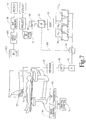
- a main magnetic field control controls super conducting permanent or resistive magnets 52 such that a substantially uniform, temporally constant magnetic field is created along a Z-axis through an examination region 54 .
- Gradient pulse amplifiers 56 apply current pulses to selected ones or pairs of whole body gradient coils 58 to create magnetic field gradients along X, Y, and Z-axis of the examination region.
- a radio frequency transmitter 60 is connected to a whole body radio frequency coil 62 to transmit RF pulses into the examination region.
- a second set of magnet coils, gradient coils and radio frequency coil are disposed below the patient as the lower pole piece.
- the whole body radio frequency coil or a surface coil array (not shown) is connected with a receiver 64 for demodulating the resultant resonance signals.
- a sequence controller 70 controls the gradient amplifiers and the digital transmitter to generate the data described in Figure 5. More specifically, the digital transmitter is caused to generate a radio frequency excitation pulse concurrently with a slab selection pulse which limits excitation to the slab 38a .
- the sequence control further controls the gradient amplifiers and the digital transmitter to generate a conventional 3D imaging sequence, except that only 1/Nth e.g. one-quarter of the phase encoded gradients along the slice select direction are generated.
- Each received data line is one dimensionally inverse Fourier transformed 80 in a read direction and stored in a first memory 82 .
- a second one dimensional inverse Fourier transform 83 is performed in the phase encode direction on the data in memory 82 to generate partially reconstructed data which is stored in a three dimensional sub-image memory 84 1 .
- the sequence controller starts generating the second subslab 38b .
- the slab select gradient is shifted along the slice select a predetermined amount, e.g. 1/Nth of the slab dimension along the slice select axis. For example, where N is 4, the slab select gradient is shifted one quarter (1 ⁇ 4) of the slab dimension.
- the process is then repeated to generate a second set of partial image data which is stored in a second sub-image memory 84 2 .
- the sequence controller then shifts the slab another 1/Nth e.g. one-quarter of the slab dimension to generate the partial image data from the third subslab 38c which is stored in a third sub-image memory 84 3 .
- the sequence controller again shifts the slab select along the slice select by one quarter of the slab dimension and generates the data from the fourth subslab 38d which is stored in fourth sub-image memory 84 4 .
- the slab select gradient is shifted in order to generate the partial sets of data.
- the partial sets of data may be generated in other ways, such as by shifting the transmitter frequency, shifting the main magnetic field B O , and/or a mechanically shifting either subject to be imaged or the imaging device.
- a sort procedure 86 sorts the twice Fourier transformed partial data sets from the memories 84 1 , 84 2 , 84 3 , 84 4 into a volume memory 88 .
- the volume memory 88 has a full set of phase encoded data in the slice select and read directions for slice 90 .
- a third one dimensional Fourier transform processor 92 performs a one dimensional Fourier transform on the data for slice 90 in the phase encode direction to generate a slice image which is stored in a final image memory 94 .
- a projection processor 96 starts projecting the slice into a corresponding line of a projection memory 98 .
- a video processor 100 converts the data in the projection memory 98 into appropriate format for display as the MIP image 40 on a video monitor 102 . It is to be appreciated that the Fourier transform is the read direction can be performed at any point from first as illustrated to last after the phase encode direction Fourier transform.
- a recrop processor 104 is used by the select a region of interest in an axial image from where a projection is calculated.
- the recrop processor 104 limits the region of the reconstructed slices which is projected.
- a user defines an area of interest in the first received image and the projection is performed accordingly. The user may also change the definition (e.g. the bounded area selected) if necessary, based on the later images, after which the data is reprojected.
- the sequence controller 70 shifts the slab select gradient by a quarter of the slab dimension and generates the next set of data for subslab 38e which is processed and stored in the first sub-image memory 84 1 .
- the sorter 86 arranges the data from partial data memories 84 1 -84 4 into a three dimensional data memory 88 , a full set of data is compiled for data along the slice 104 of Figure 5.
- This data is one dimensionally Fourier transformed 92 , stacked with the other reconstructed slices in the final image memory 94 , and projected 96 to form the next line of the MIP image 40 .
- This process continues with each shifting of the slab select gradient by one quarter of the slab dimension resulting in the generation of one more line of the projection image 40.
- the one dimensional inverse Fourier transform processor 80 may perform a one dimensional inverse Fourier transform in the read direction after the third one dimensional Fourier transform processor 92 performs a one dimensional Fourier transform on the data for slice 90 in the phase encode direction.
- the one dimensional inverse Fourier transform processor for the read direction may be positioned between the phase encode direction one dimensional Fourier transform processor 92 and the 3D memory 94 to generate a slice image which is stored in the final image memory 94 .
- each data line is one dimensionally inverse Fourier transformed in the read direction
- the set of data lines are Fourier transformed in the phase encode direction, and are then stored in the memory 88 via a line 106 thus bypassing the sub-image memories 84 1 - 84 4 and the sorter 86 .
- a primary advantage of the present magnetic resonance imaging system and method is to provide a magnetic resonance angiography (MRA) screening technique whereby a radiologist adaptively interacts with a MRA MIP imaging process to improve scanning time efficiency and clinical throughput.
- MRA magnetic resonance angiography
- Another advantage is the provision of a parallel interactive slicing MIP (maximum intensity processing) technique for magnetic resonance imaging which is utilised in combination with a Sliding Interleaved k Y (SLINKY) 3D acquisition technique.
- MIP maximum intensity processing
Landscapes
- Physics & Mathematics (AREA)
- Optics & Photonics (AREA)
- Spectroscopy & Molecular Physics (AREA)
- High Energy & Nuclear Physics (AREA)
- Condensed Matter Physics & Semiconductors (AREA)
- General Physics & Mathematics (AREA)
- Magnetic Resonance Imaging Apparatus (AREA)
Applications Claiming Priority (2)
| Application Number | Priority Date | Filing Date | Title |
|---|---|---|---|
| US08/915,622 US6023635A (en) | 1997-08-21 | 1997-08-21 | Parallel interactive slicing MIP projection for magnetic resonance imaging |
| US915622 | 1997-08-21 |
Publications (2)
| Publication Number | Publication Date |
|---|---|
| EP0899577A2 true EP0899577A2 (fr) | 1999-03-03 |
| EP0899577A3 EP0899577A3 (fr) | 2000-03-29 |
Family
ID=25436019
Family Applications (1)
| Application Number | Title | Priority Date | Filing Date |
|---|---|---|---|
| EP98305773A Withdrawn EP0899577A3 (fr) | 1997-08-21 | 1998-07-20 | Imagerie par résonance magnétique |
Country Status (3)
| Country | Link |
|---|---|
| US (1) | US6023635A (fr) |
| EP (1) | EP0899577A3 (fr) |
| JP (1) | JPH11113883A (fr) |
Families Citing this family (12)
| Publication number | Priority date | Publication date | Assignee | Title |
|---|---|---|---|---|
| US6396266B1 (en) | 1998-11-25 | 2002-05-28 | General Electric Company | MR imaging system with interactive MR geometry prescription control |
| JP3987223B2 (ja) * | 1998-12-28 | 2007-10-03 | 株式会社日立メディコ | 核磁気共鳴イメージング装置 |
| US6904163B1 (en) * | 1999-03-19 | 2005-06-07 | Nippon Telegraph And Telephone Corporation | Tomographic image reading method, automatic alignment method, apparatus and computer readable medium |
| US6795723B1 (en) | 2000-05-22 | 2004-09-21 | Koninklijke Philips Electronics, N.V. | Interleaved phase encoding acquisition for MRI with controllable artifact suppression and flexible imaging parameter selection |
| US6459264B1 (en) * | 2001-02-22 | 2002-10-01 | Mayo Foundation For Medical Education And Research | Real-time embedded magnetic resonance fluoroscopy |
| US6794869B2 (en) * | 2001-03-30 | 2004-09-21 | General Electric Company | Moving table MRI with frequency-encoding in the z-direction |
| US7209779B2 (en) * | 2001-07-17 | 2007-04-24 | Accuimage Diagnostics Corp. | Methods and software for retrospectively gating a set of images |
| US7603156B2 (en) * | 2003-07-02 | 2009-10-13 | Ge Medical Systems Global Technology Co., Llc | Systems and methods for phase encode placement |
| US7862336B2 (en) | 2004-11-26 | 2011-01-04 | Cadent Ltd. | Method and system for providing feedback data useful in prosthodontic procedures associated with the intra oral cavity |
| CN101520499B (zh) * | 2008-02-29 | 2011-12-07 | 西门子(中国)有限公司 | 磁共振成像中去除伪影的方法和装置 |
| DE102014225846B4 (de) * | 2014-12-15 | 2016-07-28 | Siemens Healthcare Gmbh | Ermittlung von Magnetresonanz-Angiographiebildern mit Time-of-Flight-Angiographie und Magnetresonanzeinrichtung |
| US11800978B2 (en) * | 2016-08-05 | 2023-10-31 | Siemens Healthcare Gmbh | Deep learning based isocenter positioning and fully automated cardiac MR exam planning |
Family Cites Families (3)
| Publication number | Priority date | Publication date | Assignee | Title |
|---|---|---|---|---|
| US5167232A (en) * | 1990-08-07 | 1992-12-01 | Ihc Hospitals, Inc. | Magnetic resonance angiography by sequential multiple thin slab three dimensional acquisition |
| DE69325508T2 (de) * | 1992-03-09 | 2000-01-27 | St. Georg's Hospital Medical School, London | Neurographische abbildungsverfahren und diffusions-anistropie |
| DE19628951C2 (de) * | 1996-07-18 | 2000-08-31 | Juergen Hennig | Verfahren der Kernspintomographie zur zeitaufgelösten Darstellung pulsatiler Gefäße (Projektionsangiographie) |
-
1997
- 1997-08-21 US US08/915,622 patent/US6023635A/en not_active Expired - Fee Related
-
1998
- 1998-07-20 EP EP98305773A patent/EP0899577A3/fr not_active Withdrawn
- 1998-08-20 JP JP10234444A patent/JPH11113883A/ja active Pending
Also Published As
| Publication number | Publication date |
|---|---|
| US6023635A (en) | 2000-02-08 |
| EP0899577A3 (fr) | 2000-03-29 |
| JPH11113883A (ja) | 1999-04-27 |
Similar Documents
| Publication | Publication Date | Title |
|---|---|---|
| JP3869337B2 (ja) | 磁気共鳴撮影装置 | |
| US4665367A (en) | Multiplexed magnetic resonance imaging of volumetric regions | |
| JP3952247B2 (ja) | 核磁気共鳴撮影装置 | |
| JP3976684B2 (ja) | 画像における動きの影響を低減する方法および装置 | |
| JP3526350B2 (ja) | 磁気共鳴イメージング装置 | |
| JPH07184881A (ja) | 磁気共鳴装置及び方法 | |
| JP2003135429A (ja) | z方向の周波数エンコードを伴うテーブル移動式MRI | |
| JPWO2002056767A1 (ja) | 高精度コイル感度マップを用いたパラレルmrイメージング | |
| WO2002046784A2 (fr) | Appareil irm et procede de balayage rapide a resolution en profondeur | |
| US6023635A (en) | Parallel interactive slicing MIP projection for magnetic resonance imaging | |
| EP1182612A2 (fr) | Méthode et appareil de traitement d'images, support d'enregistrement, et appareil d'imagerie | |
| CN1109899C (zh) | 三维图象的限带插值法和投影 | |
| US6307369B1 (en) | Autocorrection of 3D MR images for motion artifacts | |
| JP3699304B2 (ja) | 磁気共鳴撮像装置 | |
| JPH1033498A (ja) | 磁気共鳴映像法を使用するバッチ式の複数容積血管造像法 | |
| US10908248B2 (en) | Systems and methods for slice dithered enhanced resolution simultaneous multislice magnetic resonance imaging | |
| US7034532B1 (en) | Driven equilibrium and fast-spin echo scanning | |
| JP4012669B2 (ja) | 画像処理方法および装置、記録媒体並びに画像撮影装置 | |
| EP1758502A1 (fr) | Acquisition et affichage d'images de resonance magnetique nucleaire | |
| JP2002085376A (ja) | 核磁気共鳴イメージング装置および方法 | |
| JP2004000622A (ja) | 分解能の最大化及びエイリアシング・アーチファクトの排除を目的とした撮像域の自動最適化 | |
| JP4607430B2 (ja) | Rfコイルおよび磁気共鳴撮影装置 | |
| JP4699739B2 (ja) | Mri装置 | |
| JP4363625B2 (ja) | 画像処理方法および磁気共鳴撮影装置 | |
| JP4282810B2 (ja) | Mri装置 |
Legal Events
| Date | Code | Title | Description |
|---|---|---|---|
| PUAI | Public reference made under article 153(3) epc to a published international application that has entered the european phase |
Free format text: ORIGINAL CODE: 0009012 |
|
| AK | Designated contracting states |
Kind code of ref document: A2 Designated state(s): DE FR NL |
|
| AX | Request for extension of the european patent |
Free format text: AL;LT;LV;MK;RO;SI |
|
| RIN1 | Information on inventor provided before grant (corrected) |
Inventor name: TANTTU, JUKKA I. Inventor name: LIU, KECHENG |
|
| PUAL | Search report despatched |
Free format text: ORIGINAL CODE: 0009013 |
|
| RIC1 | Information provided on ipc code assigned before grant |
Free format text: 7G 01R 33/54 A, 7G 01R 33/563 B, 7G 01R 33/561 B |
|
| AK | Designated contracting states |
Kind code of ref document: A3 Designated state(s): AT BE CH CY DE DK ES FI FR GB GR IE IT LI LU MC NL PT SE |
|
| AX | Request for extension of the european patent |
Free format text: AL;LT;LV;MK;RO;SI |
|
| 17P | Request for examination filed |
Effective date: 20000915 |
|
| AKX | Designation fees paid |
Free format text: DE FR NL |
|
| RAP1 | Party data changed (applicant data changed or rights of an application transferred) |
Owner name: PHILIPS MEDICAL SYSTEMS (CLEVELAND), INC. |
|
| RAP1 | Party data changed (applicant data changed or rights of an application transferred) |
Owner name: KONINKLIJKE PHILIPS ELECTRONICS N.V. |
|
| STAA | Information on the status of an ep patent application or granted ep patent |
Free format text: STATUS: THE APPLICATION HAS BEEN WITHDRAWN |
|
| 18W | Application withdrawn |
Effective date: 20031218 |