EP0899595A2 - Méthode et appareil pour l'actionnement d'une fermeture - Google Patents
Méthode et appareil pour l'actionnement d'une fermeture Download PDFInfo
- Publication number
- EP0899595A2 EP0899595A2 EP98304748A EP98304748A EP0899595A2 EP 0899595 A2 EP0899595 A2 EP 0899595A2 EP 98304748 A EP98304748 A EP 98304748A EP 98304748 A EP98304748 A EP 98304748A EP 0899595 A2 EP0899595 A2 EP 0899595A2
- Authority
- EP
- European Patent Office
- Prior art keywords
- current
- coil
- periods
- damping
- electrical
- Prior art date
- Legal status (The legal status is an assumption and is not a legal conclusion. Google has not performed a legal analysis and makes no representation as to the accuracy of the status listed.)
- Withdrawn
Links
- 238000000034 method Methods 0.000 title claims abstract description 29
- 238000013016 damping Methods 0.000 claims abstract description 40
- 230000033001 locomotion Effects 0.000 claims abstract description 14
- 230000007246 mechanism Effects 0.000 claims abstract description 8
- 230000003287 optical effect Effects 0.000 claims 1
- 230000000694 effects Effects 0.000 description 9
- 229910000831 Steel Inorganic materials 0.000 description 7
- 239000010959 steel Substances 0.000 description 7
- 230000005484 gravity Effects 0.000 description 6
- 238000010586 diagram Methods 0.000 description 5
- 230000007704 transition Effects 0.000 description 5
- 230000001133 acceleration Effects 0.000 description 4
- 239000004065 semiconductor Substances 0.000 description 4
- 230000035939 shock Effects 0.000 description 3
- 230000005355 Hall effect Effects 0.000 description 2
- 238000013461 design Methods 0.000 description 2
- 238000005259 measurement Methods 0.000 description 2
- 230000008569 process Effects 0.000 description 2
- 230000002277 temperature effect Effects 0.000 description 2
- 238000004804 winding Methods 0.000 description 2
- 239000006096 absorbing agent Substances 0.000 description 1
- 230000009471 action Effects 0.000 description 1
- XAGFODPZIPBFFR-UHFFFAOYSA-N aluminium Chemical compound [Al] XAGFODPZIPBFFR-UHFFFAOYSA-N 0.000 description 1
- 229910052782 aluminium Inorganic materials 0.000 description 1
- 239000004411 aluminium Substances 0.000 description 1
- 230000008859 change Effects 0.000 description 1
- 230000003247 decreasing effect Effects 0.000 description 1
- CPBQJMYROZQQJC-UHFFFAOYSA-N helium neon Chemical compound [He].[Ne] CPBQJMYROZQQJC-UHFFFAOYSA-N 0.000 description 1
- 239000000463 material Substances 0.000 description 1
- 230000004048 modification Effects 0.000 description 1
- 238000012986 modification Methods 0.000 description 1
- 238000012545 processing Methods 0.000 description 1
- 230000005855 radiation Effects 0.000 description 1
- 239000000758 substrate Substances 0.000 description 1
- 238000013519 translation Methods 0.000 description 1
- 230000001960 triggered effect Effects 0.000 description 1
- 238000001429 visible spectrum Methods 0.000 description 1
Images


Classifications
-
- G—PHYSICS
- G02—OPTICS
- G02B—OPTICAL ELEMENTS, SYSTEMS OR APPARATUS
- G02B26/00—Optical devices or arrangements for the control of light using movable or deformable optical elements
- G02B26/02—Optical devices or arrangements for the control of light using movable or deformable optical elements for controlling the intensity of light
Definitions
- This invention relates to a method and apparatus for actuating a shutter.
- it relates to a shutter for interrupting and/or controlling the passage of a light beam such as a laser beam.
- Safety regulations generally require that a laser is provided with a device for ensuring that humans are not exposed to unintentional or unexpected laser radiation.
- the device is generally known as a shutter.
- the shutter may, with a low power laser, be a device that blocks the beam path and absorbs the incident beam.
- an absorbing element would not be suitable and the shutter then generally comprises a reflective element in the form of a moving mirror which moves between a shutter-open and shutter-closed position. In the shutter-open position the mirror does not intercept the laser beam and the beam passes down a desired beam delivery path. In the shutter-closed position, the mirror fully intercepts the incident beam and deflects it from the delivery path, usually into an absorber which is generally known as a beam dump.
- the direct line path from the laser is to a beam dump and the shutter element (eg. mirror) is moved into a position to reflect the laser beam into a beam delivery path.
- a laser shutter can also control passage of the laser beam, ie. in effect switch the laser beam on or off, and this is particularly useful when performing a material processing operation on a workpiece since it is often inconvenient to switch a laser on and off continually to achieve the desired effect.
- the laser beam In some operations, such as to make a discontinuous seam weld over a short distance, the laser beam must be transmitted, then blocked, in a very short time of typically 20 to 30 ms.
- the laser beam diameter may be such that the shutter element has to move through a distance of, for example, 30 mm during that time.
- very high translation speeds of the shutter element must be achieved whilst avoiding shock and vibration so as to prolong the operating life of the shutter and avoid undesired effects on the laser itself.
- a so called 'voice coil' can be used as the actuator.
- Voice coil actuators are well known direct drive limited-motion devices that utilise a permanent magnetic field and a coil winding to produce a force on the winding proportional to the current in the coil.
- the motion of the coil in each case is usually in a direction parallel to the axis of the coil.
- a preferred motion is to accelerate and then brake the moving parts in a triangular velocity-time profile.
- a high current is fed into a coil during the initial half of a traverse to provide acceleration. Then, at the mid-point of travel, the direction of current is reversed. The reversed current generates a braking force and, in an ideal set of conditions, the voice coil would then come to a halt at precisely the right position.
- the timing of the current reversal is extremely critical. For example, with the actuator arranged to have a 30 ms transit time, the changeover has to be set to be within 0.1 ms accurate to give smooth operation with no bounce at the end stop. If the current amplitudes and durations are not precisely correct, for example because of temperature effects or the effects of friction, then the coil may either stop short of the desired position or it could overrun and crash into an end stop, causing damage. If the braking current overcompensates the initial 'motor' current, then the coil assembly may start to travel back in a direction from which it started at the wrong time.
- a method of actuating a shutter element affecting the path of a laser beam, the shutter element being driven by an electrically conductive coil mechanism comprising applying a drive current to the coil for a first period of travel; reversing the current direction to provide a braking force for a second period of travel; and, during a third period, alternating between periods of electrical damping and periods in which an electrical holding current is applied.
- the electrical damping may be achieved by effectively shorting the terminals of the coil. This may be achieved by a bridge mechanism in some embodiments.
- the alternating period may be initiated at a predetermined distance from the desired end of travel position.
- an actuator for a shutter for a laser beam comprising an electrically conductive coil movable in a permanent magnetic field when a current is applied to the coil, and connected to move a shutter element when the coil moves; and means for providing electrical current to the coil, wherein the current-providing means comprises means for applying a drive current in a first direction; means for applying a braking current in the reverse direction; and means for alternating between periods of electrical damping and periods of electrical holding.
- Figure 1 illustrates generally the effect of a shutter on a laser beam.
- a laser beam travels along a path 1 (the diagram illustrates the axis of the path and also the approximate diameter of the beam 2).
- a reflective shutter mirror 3 is positioned out of the beam path and so the beam travels to a beam dump 4 where it is absorbed.
- the shutter mirror is moved to a position where it intercepts the laser beam 1.
- the shutter mirror reflects the beam to a beam delivery path 5.
- the shutter mirror must generally be relatively quickly moved between the two positions and, as shown, is movable vertically so that if drive current fails then, as a safety measure, the shutter mirror drops under gravity to its lower position shown in Figure 1(a), thus allowing the laser to pass safely to the beam dump 4.
- FIG. 2 shows schematically a voice coil mechanism.
- a coil 6 is arranged to slide axially with regard to a steel core 7.
- the coil is attached to a support 8 which moves with the coil and which bears a mirror forming a shutter (not shown).
- a steel cylinder 9 is coaxial with and surrounds the steel core 7 and is integral therewith at their respective base portions 10.
- the steel cylinder mounts a permanent magnet 11 which applies a magnetic field across coil 6.
- a current is applied to the coil 6 and, depending upon the direction of the current, the coil moves axially in one direction or the other. The amount of current determines the force on the coil and thereby its acceleration and velocity.
- a preferred motion is to accelerate and then brake the moving parts in a triangular velocity-time profile.
- Figure 3(a) shows how, in order to achieve this, a current (typically of 3-4 amperes) is fed into the coil during the initial half of the traverse (the motor phase) to provide acceleration. Then, during the second half of the traverse (the braking phase) the direction of the current is reversed. Current is applied in the first direction during a time T 1 and the second direction during a time T 2 which, in ideal conditions, would be equal.
- Figure 3(b) shows how this current produces a velocity profile which is triangular.
- Figure 3(c) illustrates the position of the coil against time and Figure 3(d) illustrates the velocity of the coil against position. It should be noted that the differential of velocity against position at the end of travel is infinite. Consequently, if the current amplitudes and durations are not precisely correct, for example because of temperature effects or the effects of friction, then the coil may stop short of the desired position or may overrun the desired position and crash into the end stop.
- the present invention provides a method of improving the situation.
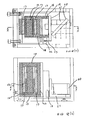
- Figures 4(a) and (b) illustrate in more detail an embodiment of the present invention.
- Figure 4(a) shows a plan view combined with a section on Y-Y
- Figure 4(b) shows a side elevation combined with a section on X-X.
- a rectangular coil 12 is arranged to move up and down a close fitting rectangular steel central vertical core 13 which terminates in respective extended steel top and bottom pieces (14,15) that are attached to vertical side members 16 to form two magnetic circuits with the central core.
- Permanent bar magnets 17 are mounted on the inner face of each respective side member and the coil 12 moves in a close fitting gap between the permanent magnets and the central core.
- the coil is carried by two aluminium side plates 18 that extend from a face plate mounted on the moving element of a linear slide 19. The moving element thereby moves with the coil 12 and is directly connected to a mirror 20 held in a mirror holder 21 to move the mirror.
- a further mirror mechanism forming part of an auxiliary laser beam pointing system may also be moved with the main mirror, as described further below.
- Damping may be achieved by effectively shorting the terminals of the coil. When this is done, the kinetic energy of the moving parts is converted into heat in the voice coil. Because the coil is moving in a magnetic field, a voltage is induced across the coil, which voltage is proportional to its instantaneous velocity. This results in a current flow which in turn generates a force on the coil that resists its motion.
- the effect of damping is seen schematically in Figure 5 in which, during a third phase of movement(the 'damping phase'), the differential of velocity against position at the end of travel is much reduced, which results in a 'soft landing' and much less risk of a crash or bounce at the end-stop if the values of T 1 and T 2 are not precisely correct.
- the transition from the braking phase to the damping phase may conveniently be triggered by means of proximity switches that detect the position of the coil relative to the shutter assembly.
- the switch is a Hall effect switch 22 actuated by a steel vane 23 mounted on the face plate of the linear slide.
- two such switches are provided, each being located approximately 3 mm from each end of travel position.
- Figure 6(a) shows a drive circuit for supplying current to the voice coil.
- the coil 12 is supplied with current from a semiconductor bridge comprising four elements D 1 , D 2 , D 3 and D 4 which are controlled by a bridge driver 24.
- the bridge driver in turn receives control signals from a control logic unit 25 which responds to the state of a shutter command signal 26 and the state of the shutter position (proximity) switches 22.
- Devices D 1 to D 4 are MOSFETS in the preferred embodiment but may be other devices which have the ability to conduct current in either direction. They are arranged in a bridge configuration and are controlled so that during the initial motor phase, the average current through the voice coil flows in a direction shown in Figure 6(b) (ie. left to right in the Figure).
- the current through the coil is output across a resistance 28 and measured by a current comparator 27.
- the design of current comparators is well known. It may comprise a differential amplifier arrangement for example, comparing the current to a fixed reference.
- the mode of operation of the bridge may alternatively employ other techniques, such as divided current chopping and steering techniques.
- the semiconductor bridge may be controlled by other methods, eg. maximum-minimum (ie. hysteresis) control in which current rise is halted when the current reaches a maximum value and current fall is halted when it reaches a minimum value.
- maximum-minimum ie. hysteresis
- techniques such as fixed frequency, variable duty cycle control may be used or other techniques.
- the bridge could be replaced by other means such as a linear amplifier, for example, utilising current feedback, to drive the voice coil.
- the coil may be energised without current control (from a voltage source). Current could then be controlled only by the resistance and inductance of the coil.
- coil current is preferably controlled at a constant value as shown in Figure 7, which illustrates the motor phase, and this may be achieved by using a constant-off-period method.
- Figure 7(b) is an enlarged view of Figure 7(a) illustrating the beginning of the motor phase.
- the drive circuit supplies increasing current to the coil and this is sensed by a current comparator 27.
- the current reaches a predetermined value I, the current supply is then turned off for a fixed off-period T.
- the value of T is approximately 50 ms.
- devices D 1 and D 4 are turned on and during the off-period only devices D 2 and D 3 are turned on, thus forcing the current to partially decay.
- the coil has both resistance R and inductance L and therefore resists rapid change of current.
- devices D 1 and D 4 are turned on again and current supply to the coil resumes until the current again reaches a value I and the next off-period begins and this is continued for the duration of the motor (acceleration) phase.
- the length of the on-period may also be typically of 50 ms or so, giving a duty cycle for the current drive of about 50%. With this technique, the value of I and/or the duty cycle can be selected to achieve the desired mean level of driving current which may typically be 3.5A.
- Figure 8 does not apply to the upward traverse, because there is a need to supply current to the coil at the upper end of the traverse firstly to prevent the coil assembly from falling under gravity at the end of the damping phase, and secondly to serve to pull the coil assembly up against the upper end-stop. This is important because it is vital that the coil assembly starts each traverse - upward and downward - from a consistent datum position.
- Figure 9(b) shows the transition from braking phase to damping phase of the upward traverse on an expanded timescale.
- a motor phase of duration T 3 of constant mean current typically -3.5A
- a braking phase of duration T 4 and constant mean current of typically +3.5 A.
- a damping phase which terminates in a steady low level negative holding current -I m .
- the coil is effectively shorted, for example by turning 'on' relevant devices in the bridge shown in Figure 6.
- the off-periods are, however, increased from the value T of typically 50 ms that are applied during the motor- and braking-phases, typically to 10 T, ie. approximately 500 ms.
- the current supply stays on until a current level of -I' is reached, at which time an off-period of 10 T starts.
- the damping phase commences, the coil is shorted and the current starts to fall.
- the current supply drives the current down past zero to -I, at which point the next off-period commences.
- the current level then decays because the coil is shorted but is then restored to -I' during the next on-period.
- the value of I' may be set to an appropriate level so that, during this steady state, the mean current I m is sufficient to hold the coil assembly at the upper position against gravity. In the preferred embodiment, I m is about 600 mA. This is approximately twice the value required to hold the coil assembly stationary against gravity. It will be noted that during the damping phase (ie.
- initial values of T 1 to T 4 are determined by means of software which involves an initialisation routine which is summarised in the flow diagram of Figure 10.
- the coil assembly is initially at the lower end-stop where holding current is applied alternately with shorting, similar to the damping phase shown in Figure 9.
- the program runs a series of trials in which the coil assembly is energised in turn with a series of current profiles and the system determines whether the upper proximity switch 22 has been actuated as a result of the ensuing motion.
- the damping phase resumes, with the result that the coil assembly drifts gently down to the bottom end-stop under the alternating effect of shorting and holding current.
- time T 3 is chosen to be 0.1 ms.
- a first trial run is then instigated (101).
- Time t s is measured (102) and if t s ⁇ T 3 + T 4 (103), then the routine has been successful and is stopped (104). If not, then a determination is made whether the top switch has been actuated (105).
- time T 4 is increased by, for example, 0.1 ms (106) and a further trial run commences. If the top switch has not been actuated during that run then time T 3 is increased by 0.1 ms (107) and a new trial run is commenced.
- a motor pulse of only 0.1 ms is applied to the coil. If the upper switch is not actuated then, on subsequent trials, the motor pulse length is progressively increased in 0.1 ms increments until the switch is finally actuated. On the next trial, a brake pulse of 0.1 ms duration is added on the end of the previous motor pulse value. Thereafter, if the switch was actuated on the previous trial, the brake pulse width is increased by 0.1 ms on the next trial. Conversely, if the switch was not actuated on the previous trial, the motor pulse width is increased by 0.1 ms for next trial. The process continues until the duration of the motor pulse T 3 plus the duration of the braking pulse T 4 is equal to t s .
- This value may be designated T m .
- the duration of the motor pulse is initially set to T 3 and the duration of the braking pulse is set to (T m - T 3 ).
- Typical values for T 3 and T m for the upward traverse are 18.5 ms and 32 ms respectively.
- the measurements and adjustments are then carried out continually to ensure optimised operation throughout the duration of a process.
- the transition from the braking phase to the damping phase is normally initiated, in the case of the upward traverse for example, by actuation of the upper proximity switch. However, if the switch is not actuated for some reason, then the damping phase is automatically initiated at the end of the braking current pulse, if not initiated earlier by the proximity switch.
- actuation of the lower proximity switch is the primary criterion and the measurement of t s relates to actuation of the lower switch.
- the principles and strategy are analogous to those for the upward traverse.
- Typical values for T 1 and T p are 15.5 ms and 29 ms respectively.
- Non-contact switches are preferable to reduce resistance to motion.
- holding current may be applied at both ends of travel of the assembly and this may be particularly necessary if the shutter orientation departs significantly from vertical since the shutter element may be arranged to move in any plane.
- the position of the coil assembly is sensed at two positions by two switches. These switches may alternatively be positioned at distances greater or less than 3 mm from their associated end-stops or end-of-travel positions.
- Additional or alternative positional or velocity data may be obtained by using different types of switches or position or velocity sensing means.
- MOSFET devices shown in the preferred embodiment may be replaced with other suitable devices, non-limiting examples of which are insulated gate bipolar transistors (IGBTs), bipolar transistors or SCRs (thyristors). In the case of devices such as transistors and SCRs, parallel diodes may also be required.
- IGBTs insulated gate bipolar transistors
- SCRs thyristors
- parallel diodes may also be required.
- the shutter mirror need not be disposed at 45° to the incident beam as shown in the preferred embodiment and may be disposed at any suitable angle, eg. any angle within 15° to 75° or angles beyond this.
- the shutter element may equally be an absorptive element, rather than the reflective one shown. If the shutter is a reflective one, it need not be a planar one.
- the substrate may be a right angle prism for example or be of other shape or configuration.
- the shutter element need not be linearly translated at all and could be for example, mounted on a rotating element to rotate in and out of position, and driven by a voice coil arrangement.
- a low power visible pointing beam allows the components along the beam path to be visually aligned safely to the beam path. It also indicates to the user where the principal beam will be incident - for example, on a workpiece - when it subsequently passes down the beam path. This is particularly useful for example when programming a robotic beam delivery head in teaching mode.
- the pointing beam is typically provided by a 2mW helium-neon laser (wavelength 633 nm) or by a 3mW semiconductor diode laser (wavelength 635 nm) in preferred embodiment, although it can of course be provided by other types of laser and/or different wavelengths and powers.
- a shutter mirror 40 for a principal beam 41 is moved generally vertically into and out of the beam path of the principal beam by an actuator mechanism.
- a second, independent, laser beam is used as a pointing beam and is provided by, for example, a laser diode unit 43.
- the pointing beam traverses generally horizontally to a first, fixed, auxiliary mirror 44 which directs the beam vertically downward to a second auxiliary mirror 45.
- the second mirror 45 is mounted on an extension of a mount 46 that carries the main shutter mirror 40 and is thereby displaced with the shutter mirror.
- the second mirror is arranged at a fixed angle so as to direct the pointing beam 42 horizontally in a direction parallel to the principal beam path 47.
Landscapes
- Physics & Mathematics (AREA)
- General Physics & Mathematics (AREA)
- Optics & Photonics (AREA)
- Shutters For Cameras (AREA)
- Lasers (AREA)
- Stopping Of Electric Motors (AREA)
- Mechanical Light Control Or Optical Switches (AREA)
- Control Of Linear Motors (AREA)
Applications Claiming Priority (2)
| Application Number | Priority Date | Filing Date | Title |
|---|---|---|---|
| GB9714134 | 1997-07-05 | ||
| GBGB9714134.5A GB9714134D0 (en) | 1997-07-05 | 1997-07-05 | Method and apparatus for actuating a shutter |
Publications (2)
| Publication Number | Publication Date |
|---|---|
| EP0899595A2 true EP0899595A2 (fr) | 1999-03-03 |
| EP0899595A3 EP0899595A3 (fr) | 1999-05-06 |
Family
ID=10815374
Family Applications (1)
| Application Number | Title | Priority Date | Filing Date |
|---|---|---|---|
| EP98304748A Withdrawn EP0899595A3 (fr) | 1997-07-05 | 1998-06-17 | Méthode et appareil pour l'actionnement d'une fermeture |
Country Status (3)
| Country | Link |
|---|---|
| EP (1) | EP0899595A3 (fr) |
| JP (1) | JPH1184268A (fr) |
| GB (1) | GB9714134D0 (fr) |
Cited By (10)
| Publication number | Priority date | Publication date | Assignee | Title |
|---|---|---|---|---|
| ES2301288A1 (es) * | 2005-08-05 | 2008-06-16 | Easy Laser, S.L. | Dispositivo inteligente de obturacion del haz laser y metodo de actuacion. |
| WO2011022769A1 (fr) * | 2009-08-25 | 2011-03-03 | Monash University | Obturateur et procédé d'utilisation |
| CN102157900A (zh) * | 2011-03-17 | 2011-08-17 | 华中科技大学 | 一种高功率激光器的机械光闸 |
| US9577551B2 (en) | 2013-04-26 | 2017-02-21 | Asahi Kasei Microdevices Corporation | Motor drive apparatus |
| CN108710202A (zh) * | 2018-05-24 | 2018-10-26 | 中国工程物理研究院应用电子学研究所 | 一种电动调节光闸装置 |
| CN110673161A (zh) * | 2018-07-03 | 2020-01-10 | 度逢株式会社 | 物体检测装置及其物体检测方法、以及记录介质 |
| EP3575861A4 (fr) * | 2017-01-25 | 2020-02-12 | Shanghai Micro Electronics Equipment (Group) Co., Ltd. | Dispositif obturateur et procédé de commande associé, aligneur de masque et procédé de commande de dose d'exposition associé |
| EP3822689A1 (fr) * | 2019-11-14 | 2021-05-19 | TRUMPF Schweiz AG | Obturateur de faisceau, dispositif laser et procédé de fonctionnement associé |
| CN114609747A (zh) * | 2020-12-04 | 2022-06-10 | 台湾东电化股份有限公司 | 光学元件驱动机构 |
| US12007552B2 (en) | 2020-04-24 | 2024-06-11 | University Of Rochester | Fail safe beam shutter devices and systems |
Families Citing this family (3)
| Publication number | Priority date | Publication date | Assignee | Title |
|---|---|---|---|---|
| JP4695956B2 (ja) * | 2004-09-30 | 2011-06-08 | 富士フイルム株式会社 | 微小電気機械式変調素子及び微小電気機械式変調素子アレイ並びに画像形成装置 |
| JP5092206B2 (ja) * | 2005-06-09 | 2012-12-05 | シンフォニアテクノロジー株式会社 | リニアアクチュエータの位置決め制御方法及び装置 |
| JP5330718B2 (ja) * | 2008-03-19 | 2013-10-30 | シャープ株式会社 | カメラシステム、ボイスコイルモータの駆動装置、およびボイスコイルモータの駆動方法 |
Family Cites Families (6)
| Publication number | Priority date | Publication date | Assignee | Title |
|---|---|---|---|---|
| JPS55130525A (en) * | 1979-03-30 | 1980-10-09 | Canon Inc | Bound preventing device of electromagnetical drive shutter |
| US4839679A (en) * | 1987-06-18 | 1989-06-13 | General Electric Corp. | Dual voice coil shutter |
| JPH039228A (ja) * | 1989-06-05 | 1991-01-17 | Jeol Ltd | 駆動鏡位置検出装置 |
| US5107366A (en) * | 1989-09-28 | 1992-04-21 | Nicolet Instrument Corporation | High efficiency electromagnetic coil apparatus and method |
| FR2661007B1 (fr) * | 1990-04-12 | 1994-04-01 | Etat Francais Delegue Armement | Dispositif d'aiguillage optique pour faisceau laser. |
| US5596590A (en) * | 1996-01-25 | 1997-01-21 | Cymer Laser Technologies | Beam diverting shutter for a laser beam |
-
1997
- 1997-07-05 GB GBGB9714134.5A patent/GB9714134D0/en not_active Ceased
-
1998
- 1998-06-17 EP EP98304748A patent/EP0899595A3/fr not_active Withdrawn
- 1998-07-06 JP JP19053698A patent/JPH1184268A/ja active Pending
Cited By (15)
| Publication number | Priority date | Publication date | Assignee | Title |
|---|---|---|---|---|
| ES2301288A1 (es) * | 2005-08-05 | 2008-06-16 | Easy Laser, S.L. | Dispositivo inteligente de obturacion del haz laser y metodo de actuacion. |
| ES2301288B1 (es) * | 2005-08-05 | 2009-02-16 | Easy Laser, S.L. | Dispositivo inteligente de obturacion del haz laser y metodo de actuacion. |
| WO2011022769A1 (fr) * | 2009-08-25 | 2011-03-03 | Monash University | Obturateur et procédé d'utilisation |
| CN102157900A (zh) * | 2011-03-17 | 2011-08-17 | 华中科技大学 | 一种高功率激光器的机械光闸 |
| CN102157900B (zh) * | 2011-03-17 | 2012-11-21 | 华中科技大学 | 一种高功率激光器的机械光闸 |
| US9577551B2 (en) | 2013-04-26 | 2017-02-21 | Asahi Kasei Microdevices Corporation | Motor drive apparatus |
| US10983415B2 (en) | 2017-01-25 | 2021-04-20 | Shanghai Micro Electronics Equipment (Group) Co., Ltd. | Shutter device, method of controlling same, photolithography machine, and method of controlling exposure dose thereof |
| EP3575861A4 (fr) * | 2017-01-25 | 2020-02-12 | Shanghai Micro Electronics Equipment (Group) Co., Ltd. | Dispositif obturateur et procédé de commande associé, aligneur de masque et procédé de commande de dose d'exposition associé |
| CN108710202A (zh) * | 2018-05-24 | 2018-10-26 | 中国工程物理研究院应用电子学研究所 | 一种电动调节光闸装置 |
| CN110673161A (zh) * | 2018-07-03 | 2020-01-10 | 度逢株式会社 | 物体检测装置及其物体检测方法、以及记录介质 |
| CN110673161B (zh) * | 2018-07-03 | 2023-04-18 | 度逢株式会社 | 物体检测装置及其物体检测方法、以及记录介质 |
| EP3822689A1 (fr) * | 2019-11-14 | 2021-05-19 | TRUMPF Schweiz AG | Obturateur de faisceau, dispositif laser et procédé de fonctionnement associé |
| WO2021094475A1 (fr) | 2019-11-14 | 2021-05-20 | Trumpf Schweiz Ag | Interrupteur optique, ensemble laser et procédé de fonctionnement associé |
| US12007552B2 (en) | 2020-04-24 | 2024-06-11 | University Of Rochester | Fail safe beam shutter devices and systems |
| CN114609747A (zh) * | 2020-12-04 | 2022-06-10 | 台湾东电化股份有限公司 | 光学元件驱动机构 |
Also Published As
| Publication number | Publication date |
|---|---|
| GB9714134D0 (en) | 1997-09-10 |
| JPH1184268A (ja) | 1999-03-26 |
| EP0899595A3 (fr) | 1999-05-06 |
Similar Documents
| Publication | Publication Date | Title |
|---|---|---|
| EP0899595A2 (fr) | Méthode et appareil pour l'actionnement d'une fermeture | |
| US5247140A (en) | Brake control system in elevator control apparatus | |
| EP0675779B1 (fr) | Tete de soudage a reponse rapide | |
| US7898196B2 (en) | Motor driving apparatus for driving and braking brake-equipped motor | |
| EP0290024B1 (fr) | Méthode d'accès d'un entraînement à disque optique au moyen de saut multi-piste et un circuit à cet effet | |
| US6169405B1 (en) | Functional test process for a mechanical switching element | |
| EP0788418B1 (fr) | Dispositif a souder des goujons | |
| CN104852255B (zh) | 激光器机械光闸装置 | |
| DE3619515A1 (de) | Optische informations-aufzeichnungs- und/oder -wiedergabeeinrichtung | |
| KR880000420B1 (ko) | 주축 정위치 제어장치 | |
| US6762866B2 (en) | High speed mechanical laser shutter | |
| JP2004537421A (ja) | 短時間アーク溶接システム及び短時間アーク溶接方法 | |
| US4904909A (en) | Controller for electric clamp | |
| JP2021027684A (ja) | サーボモータの制御装置 | |
| CN204651669U (zh) | 激光器机械光闸装置 | |
| US5684767A (en) | Track jump control circuit of optical disk apparatus properly controlling timing of accelerating pulses and decelerating pulses, and performing stable track jump | |
| US10320320B2 (en) | Method for controlling an electrical drive, and electrical drive | |
| EP0127854B1 (fr) | Dispositif pour positionner des pièces à usiner dans des machines | |
| CA2400721C (fr) | Procede de soudage d'un goujon sur un piece et dispositif de soudage de goujons | |
| SU877626A2 (ru) | Электромагнитный молот | |
| JPH01269236A (ja) | 光学ヘッド制御回路 | |
| JPS6244643B2 (fr) | ||
| JPH0224013A (ja) | ドリルスタンド | |
| JPH01170589A (ja) | レーザ加工機 | |
| JP2019140812A (ja) | ワーク接触装置、ワーク接触方法、およびワーク接触装置の製造方法 |
Legal Events
| Date | Code | Title | Description |
|---|---|---|---|
| PUAI | Public reference made under article 153(3) epc to a published international application that has entered the european phase |
Free format text: ORIGINAL CODE: 0009012 |
|
| AK | Designated contracting states |
Kind code of ref document: A2 Designated state(s): AT BE CH CY DE DK ES FI FR GB GR IE IT LI LU MC NL PT SE |
|
| AX | Request for extension of the european patent |
Free format text: AL;LT;LV;MK;RO;SI |
|
| PUAL | Search report despatched |
Free format text: ORIGINAL CODE: 0009013 |
|
| AK | Designated contracting states |
Kind code of ref document: A3 Designated state(s): AT BE CH CY DE DK ES FI FR GB GR IE IT LI LU MC NL PT SE |
|
| AX | Request for extension of the european patent |
Free format text: AL;LT;LV;MK;RO;SI |
|
| AKX | Designation fees paid | ||
| REG | Reference to a national code |
Ref country code: DE Ref legal event code: 8566 |
|
| STAA | Information on the status of an ep patent application or granted ep patent |
Free format text: STATUS: THE APPLICATION IS DEEMED TO BE WITHDRAWN |
|
| 18D | Application deemed to be withdrawn |
Effective date: 19991109 |