EP0899677A2 - Dispositif de lecture pour un système électronique d'identification - Google Patents
Dispositif de lecture pour un système électronique d'identification Download PDFInfo
- Publication number
- EP0899677A2 EP0899677A2 EP98306943A EP98306943A EP0899677A2 EP 0899677 A2 EP0899677 A2 EP 0899677A2 EP 98306943 A EP98306943 A EP 98306943A EP 98306943 A EP98306943 A EP 98306943A EP 0899677 A2 EP0899677 A2 EP 0899677A2
- Authority
- EP
- European Patent Office
- Prior art keywords
- reader
- heads
- transponder
- transponders
- phase
- Prior art date
- Legal status (The legal status is an assumption and is not a legal conclusion. Google has not performed a legal analysis and makes no representation as to the accuracy of the status listed.)
- Granted
Links
Images


Classifications
-
- G—PHYSICS
- G06—COMPUTING OR CALCULATING; COUNTING
- G06K—GRAPHICAL DATA READING; PRESENTATION OF DATA; RECORD CARRIERS; HANDLING RECORD CARRIERS
- G06K7/00—Methods or arrangements for sensing record carriers, e.g. for reading patterns
- G06K7/10—Methods or arrangements for sensing record carriers, e.g. for reading patterns by electromagnetic radiation, e.g. optical sensing; by corpuscular radiation
- G06K7/10009—Methods or arrangements for sensing record carriers, e.g. for reading patterns by electromagnetic radiation, e.g. optical sensing; by corpuscular radiation sensing by radiation using wavelengths larger than 0.1 mm, e.g. radio-waves or microwaves
- G06K7/10316—Methods or arrangements for sensing record carriers, e.g. for reading patterns by electromagnetic radiation, e.g. optical sensing; by corpuscular radiation sensing by radiation using wavelengths larger than 0.1 mm, e.g. radio-waves or microwaves using at least one antenna particularly designed for interrogating the wireless record carriers
- G06K7/10336—Methods or arrangements for sensing record carriers, e.g. for reading patterns by electromagnetic radiation, e.g. optical sensing; by corpuscular radiation sensing by radiation using wavelengths larger than 0.1 mm, e.g. radio-waves or microwaves using at least one antenna particularly designed for interrogating the wireless record carriers the antenna being of the near field type, inductive coil
-
- G—PHYSICS
- G06—COMPUTING OR CALCULATING; COUNTING
- G06K—GRAPHICAL DATA READING; PRESENTATION OF DATA; RECORD CARRIERS; HANDLING RECORD CARRIERS
- G06K7/00—Methods or arrangements for sensing record carriers, e.g. for reading patterns
- G06K7/0008—General problems related to the reading of electronic memory record carriers, independent of its reading method, e.g. power transfer
-
- G—PHYSICS
- G06—COMPUTING OR CALCULATING; COUNTING
- G06K—GRAPHICAL DATA READING; PRESENTATION OF DATA; RECORD CARRIERS; HANDLING RECORD CARRIERS
- G06K7/00—Methods or arrangements for sensing record carriers, e.g. for reading patterns
- G06K7/10—Methods or arrangements for sensing record carriers, e.g. for reading patterns by electromagnetic radiation, e.g. optical sensing; by corpuscular radiation
- G06K7/10009—Methods or arrangements for sensing record carriers, e.g. for reading patterns by electromagnetic radiation, e.g. optical sensing; by corpuscular radiation sensing by radiation using wavelengths larger than 0.1 mm, e.g. radio-waves or microwaves
- G06K7/10019—Methods or arrangements for sensing record carriers, e.g. for reading patterns by electromagnetic radiation, e.g. optical sensing; by corpuscular radiation sensing by radiation using wavelengths larger than 0.1 mm, e.g. radio-waves or microwaves resolving collision on the communication channels between simultaneously or concurrently interrogated record carriers.
- G06K7/10029—Methods or arrangements for sensing record carriers, e.g. for reading patterns by electromagnetic radiation, e.g. optical sensing; by corpuscular radiation sensing by radiation using wavelengths larger than 0.1 mm, e.g. radio-waves or microwaves resolving collision on the communication channels between simultaneously or concurrently interrogated record carriers. the collision being resolved in the time domain, e.g. using binary tree search or RFID responses allocated to a random time slot
- G06K7/10039—Methods or arrangements for sensing record carriers, e.g. for reading patterns by electromagnetic radiation, e.g. optical sensing; by corpuscular radiation sensing by radiation using wavelengths larger than 0.1 mm, e.g. radio-waves or microwaves resolving collision on the communication channels between simultaneously or concurrently interrogated record carriers. the collision being resolved in the time domain, e.g. using binary tree search or RFID responses allocated to a random time slot interrogator driven, i.e. synchronous
-
- G—PHYSICS
- G06—COMPUTING OR CALCULATING; COUNTING
- G06K—GRAPHICAL DATA READING; PRESENTATION OF DATA; RECORD CARRIERS; HANDLING RECORD CARRIERS
- G06K7/00—Methods or arrangements for sensing record carriers, e.g. for reading patterns
- G06K7/10—Methods or arrangements for sensing record carriers, e.g. for reading patterns by electromagnetic radiation, e.g. optical sensing; by corpuscular radiation
- G06K7/10009—Methods or arrangements for sensing record carriers, e.g. for reading patterns by electromagnetic radiation, e.g. optical sensing; by corpuscular radiation sensing by radiation using wavelengths larger than 0.1 mm, e.g. radio-waves or microwaves
- G06K7/10316—Methods or arrangements for sensing record carriers, e.g. for reading patterns by electromagnetic radiation, e.g. optical sensing; by corpuscular radiation sensing by radiation using wavelengths larger than 0.1 mm, e.g. radio-waves or microwaves using at least one antenna particularly designed for interrogating the wireless record carriers
- G06K7/10356—Methods or arrangements for sensing record carriers, e.g. for reading patterns by electromagnetic radiation, e.g. optical sensing; by corpuscular radiation sensing by radiation using wavelengths larger than 0.1 mm, e.g. radio-waves or microwaves using at least one antenna particularly designed for interrogating the wireless record carriers using a plurality of antennas, e.g. configurations including means to resolve interference between the plurality of antennas
Definitions
- THIS invention relates to electronic identification systems including an interrogator and a plurality of transponders.
- the invention more particularly relates to Interrogators or readers forming part of such systems, especially radio frequency (RF) identification systems.
- RF radio frequency
- Known electronic identification systems of the aforementioned kind include a reader including a transmitter for transmitting an energizing field or interrogation signal to the transponders; and a receiver for receiving a response signal from the transponders.
- a microprocessor in the reader identifies a particular transponder by identification code data unique to the transponder forming part of a backscattered response signal.
- the reader Upon receipt of the identification code data by the reader and thus upon identification of the transponder, the reader transmits an acknowledgement signal to the transponder to switch the transponder to a catnap mode wherein it stops responding to the interrogation signal, while still being energized.
- the transponder After the energizing signal has been removed from the transponder for a period longer than a reset period (typically shorter than two seconds), the transponder reverts to a normal operational mode wherein it responds as hereinbefore described with identification code data upon being energized.
- a reset period typically shorter than two seconds
- a reader arrangement for an electronic identification system including a plurality of reader heads for energizing transponders to be read; and control means for time multiplexing activation of the reader heads.
- the activation may be multiplexed by switching activation of the reader heads in a multi-phase sequential pattern including a first phase for activating a first set of the reader heads and at least one further phase for activating at least one further set of said reader heads, so that a complete cycle plus at least the first phase of a subsequent cycle is completed within a time period not longer than a reset period of the transponders, the reset period being the period between removal of an energizing signal from a transponder and the transponder re-entering a normal operational mode.
- the reader heads may be arranged in an array, such as a linear array or a rectangular array.
- the reader heads in the first set and the reader heads in the at least one further set may be arranged in alternating relationship, so that radiation patterns associated with simultaneously activated heads do not overlap.
- the arrangement may be stationary. In other embodiments at least the reader heads may be moveable past a volume including transponders to be read.
- the reader arrangement may include a central reader and the control means may include fast switching switch means, for example PIN diodes, for connecting the heads to the central reader in the multi-phase sequence.
- the control means may include fast switching switch means, for example PIN diodes, for connecting the heads to the central reader in the multi-phase sequence.
- the reader heads of that set may be connected to the reader via a power splitter arrangement.
- multiple reader arrays may be utilized and in such embodiments adjacent heads in neighbouring arrays are controlled such that they are not activated simultaneously.
- the arrangement may further include at least one energizing means including at least one energizing signal transmitter for preventing the transponders from exiting the catnap mode and thus resetting to a normal operational mode of the transponder.
- the reader head array may be positioned between a leading energizing array and a trailing energizing array.
- At least some of the heads may be arranged such that central axes of radiation patterns associated with the heads extend transversely relative to one another.
- the axes may for example extend perpendicular relative to one another.
- Each head may include an antenna adapted to transmit or receive signals the polarization of which is not limited to one plane.
- a reader arrangement for an electronic identification system including a plurality of reader heads, each head being associated with a radiation pattern wherein it transmits an energizing signal for energizing transponders; at least some of the heads being arranged such that the central axes of respective patterns extend substantially transversely relative to one another.
- a reader arrangement for an electronic identification system including an antenna adapted to transmit or receive signals the polarization of which is not limited to one plane.
- a reader head for an electronic identification system, the reader head including a plurality of energizing elements for energizing transponders to be read; and wherein the elements, in use, are activated in a time-division multiplexing manner.
- the energizing elements may be first and second antenna elements arranged for transmitting or receiving signals polarized in first and second planes respectively and the elements may be activated by switching activation of the elements in a multi-phase sequential pattern including a first phase for activating the first element and a second phase for activating the second element, so that a complete cycle plus at least the first phase of a subsequent cycle is completed within a time period not longer than a reset period of the transponders, the reset period being the period between removal of an energizing signal from a transponder and the transponder re-entering a normal operational mode.
- Also included within the scope of the present invention is a method of reading a plurality of transponders including the steps of: providing a plurality of reader elements; and activating the elements in a time-division multiplexing manner, to energize the transponders.
- Each transponder may be of a kind having an operational mode wherein it is responsive to energization by a reader by transmitting data to be received by the reader; and a catnap mode which the transponder enters after reception of the data has been acknowledged by the reader and wherein the transponder remains until energization is removed from the transponder, the transponder further being adapted to re-enter the operational mode a reset period after energization has been removed therefrom
- the activating step may include the step of switching activation of the reader elements in a multi-phase sequential pattern comprising a first phase for activating a first set of said reader elements and at least one further phase for activating at least one further set of said reader elements, so that a complete cycle plus at least the first phase of a subsequent cycle is completed within a time period not longer than the reset period of the transponders.
- the elements may form part of reader heads and in one embodiment of the method the reader heads may be kept stationary and may be arranged such that radiation pattems associated with the reader heads collectively cover a volume to be read.
- the method may include the steps of moving the reader heads past a volume to be read; and utilizing energizing means to keep transponders not in energizing fields associated with the reader heads in an operational mode, so that they are not affected by scattered energy originating from the reader heads and/or to keep transponders already read in the catnap mode.
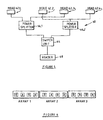
- a prior art identification system is generally designated by the reference numeral 10 in figure 1.
- the system 10 includes a reader 12 comprising a transmitter for transmitting an energizing field 14 or interrogation signal to transponders 16.
- the reader further comprises receiver means for receiving a response signal from the transponders.
- a microprocessor in the reader 12 identifies a particular transponder (such as TRP 1 ) from identification code data forming part of a backscattered response signal.
- the identification code data is unique to the transponder.
- the reader Upon receipt of the data by the reader 12 and thus upon identification of the transponder TRP 1 , the reader transmits an acknowledgement signal to switch the transponder to a catnap mode wherein it stops responding to the interrogation signal, while still being energized.
- a transponder is switched as aforesaid, a counter in the reader is incremented, to keep count of the transponders read.
- the transponder 16 After the energizing field 14 has been removed from the transponder for a period longer than a reset period (typically shorter than 2 seconds) the transponder 16 reverts to its normal operational mode wherein it will respond with the identification data upon being energized.
- FIG 2 there is shown a block diagram of a system 20 for alleviating the aforementioned problem.
- the system comprises a reader head arrangement 22 including a plurality of spaced reader heads 22.1 to 22.4 arranged in an array, to cover a reading volume 24.
- a reading volume is a volume that contains transponders that must be subjected to identification recording or identification verification procedures.
- the reading volume may be defined by a shelf 26 and the transponders (not shown) may be mounted on articles 28.1 to 28.n of a similar nature, which articles must be counted by the aforementioned procedures.
- Each head is associated with a respective radiation pattern 23.1 to 23.4 of generally conical shape having a respective central axis 25.1 to 25.4.
- the system further comprises switch control means 29 connected to the reader heads 22.1 to 22.4 for time-division multiplexing activation of the heads by switching activation of the heads in a multi-phase sequential pattern comprising a first phase for activating a first set of said reader heads only and at least a second phase for activating another set of said reader heads only, so that a complete activation cycle plus at least the first phase of a subsequent cycle is completed within a time period equal to the aforementioned reset period of the transponders.
- reader heads 22.1 and 22.3 are activated simultaneously and in the second phase, only heads 22.2 and 22.4 are activated simultaneously. In this way adjacent ones of the reader heads 22.1 to 22.4 are not switched on simultaneously, so that the effects of multipath signals and signal cancellation may be alleviated.
- a second embodiment of the reader arrangement is designated 30 in the block diagram in figure 3.
- the arrangement 30 comprises a reader and switch controller 32 connected by coaxial cable 34 to a switching box 36. Signals to be transmitted and signals received propagate in said cable.
- Switch control lines 38 connected between the controller 32 and the box 36, transmit switch control signals to the box 36.
- Reader head 38.1 is connected via cable 39.1 to the box 36 and reader head 38.2 is connected via cable 39.2 to the box 36.
- heads 38.1 and 38.2 are activated altemately and repeatedly in cycles during the identification recording and identification verification procedures, so that a complete cycle plus the first phase of a subsequent cycle is completed within the reset period.
- An example of a suitable circuit is designated 40 in figure 4.
- the circuit comprises a central reader 42 connected to reader heads 44.1 and 44.2.
- a controller 46 in the form of a switching matrix is also connected to the circuit.
- the circuit further comprises PIN diode switches 48.1 and 48.2, isolation chokes 50.1 and 50.2 having a very high impedance at the operating frequency, isolation capacitors 52.1 and 52.2 to prevent switching voltages from reaching the reader 42 and a current limiting and bias resistor 54.
- the signal at the switching control input 46.1 is a dual state binary signal.
- the switching matrix causes logic high and logic low signals to appear alternately and repeatedly at outputs 46.2 and 46.3.
- the signal at output 46.2 is out of phase with the signal at output 46.3.
- output 42.3 is high, a high voltage is applied to diode 48.1 and current flows through the diode switch causing it to conduct and thus passing the reader transmit and receive signals to and from head 44.1.
- the current also flows through the resistor 54, causing diode 48.2 to be reverse biased and therefore provides isolation of head 44.2 from the reader 42.
- diode 48.2 When output 46.2 becomes high, diode 48.2 is forward biased to pass the reader transmit and receive signals to and from head 44.2 and diode 48.1 is reverse biased, to provide isolation of head 44.1 from the reader 42.
- heads 62.1 and 62.3 which are activated simultaneously are connected to a switch unit 64 via power splitter 66.1 and heads 62.2 and 62.4 which are activated simultaneously, but sequentially with heads 62.1 and 62.3, are connected via a power splitter 66.2 to switch unit 64.
- Switch unit 64 is connected to the reader 68.
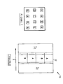
- the reader arrangement or reader head arrangement may be in the form of an array, such as a linear array or a rectangular array. These configurations are shown in figures 6 and 7. When more than one array is used (as shown in figure 6) the control is such that adjacent heads in two neighbouring arrays are not activated at the same time. In the arrangements shown in figures 6 and 7, the heads marked A are switched simultaneously, thereafter the heads marked B , thereafter the heads marked C , thereafter the heads marked D and thereafter the heads marked A , all within a time period equal to or shorter than the aforementioned reset period.
- the transponders already read are cyclically re-energized within their reset periods during each cycle of the verification procedure, thereby to prevent them from switching from the catnap mode to the normal operational mode wherein they could be read for a second time.
- the verification cycles only transponders not read during preceding cycles are read. At the end of the verification procedure all the transponders should have been read and a total number equal to the number of transponders and thus articles in the volume should be available.
- a mobile reader arrangement 70 includes a reader array 72 including heads A and B and which array is flanked by a leading energizing array 74 and a trailing energizing array 76.
- the assembly is caused to move in direction C , along a reading volume (not shown) to read transponders (also not shown) located in that volume.
- the reader array 72 operates on the principles described hereinbefore in that readers in the array are activated sequentially within the reset period, adjacent readers are not activated at the same time; and upon having read a transponder, that transponder is acknowledged and switched to the catnap mode.
- the energizing arrays on the other hand do not read the transponders nor acknowledge receipt of the identification code (thereby to switch the transponders to the catnap mode), but keep the transponders that have been read in the catnap mode. It is believed that this configuration also relieves the effects of scattering and accidental double reading of transponders illuminated by scattered energization signals.
- FIG. 9 A further embodiment of the invention is diagrammatically illustrated in figure 9.
- the reader heads 90.1 to 90.3 of the arrangement are arranged such that the central axes 92.1 to 92.3 of their radiation patterns extend transversely relative to one another, preferably substantially orthogonally relative to one another through the reading volume 94.
- the heads are preferably activated in a sequential pattern as hereinbefore described and may transmit on the same or different frequencies, to ensure that randomly orientated transponders are all energized and read. Larger arrangements of simultaneously activated heads may also be provided.
- the invention further extends to a reader head including an antenna arrangement adapted to transmit an interrogation signal with its polarization not limited to one plane and to receive response signals the polarization of which is also not limited to one plane.
- the antenna element 100 of head 102 is helically shaped, so that a circularly polarized signal E is transmitted.
- the head 104 further includes a controller 106 for controlling a transmitter 108 for generating the energizing signal E , a receiver 110 for receiving the backscatter modulated signal and a routing device 112 for connecting either the transmitter 108 or the receiver 110 to the antenna element 100.
- transponders not shown
- the antennas also not shown
- the antennas of which are orientated randomly relative to the orientation of the antenna element 100
- the antenna element 100 will also be able to receive randomly polarized backscatter modulated signals from the transponders.
- two orthogonal linear antenna elements 120 and 122 are connected at their respective feed points to feed lines 124 and 126 respectively.
- feed lines 124 and 126 there are provided adjustable delay line elements 128 and 130 respectively,
- the feed lines 124 and 126 are connected to transmitter 132.
- the phases of the signals propagating in the lines 124 and 126 are adjustable relative to one another, resulting in non-linear polarization of the transmitted energizing signal F .
- the non-linear polarized signal F should be receivable by the antennas (not shown) of transponders (also not shown) orientated randomly relative to the antenna elements 120 and 122.
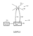
- FIG 12 there is shown a further embodiment of a reader head according to the invention.
- the head 140 includes an antenna arrangement 142 including vertically and horizontally polarized antenna elements 144 and 146 respectively. Elements 144 and 146 are connected to switching box 152 via cables 148 and 150, respectively. The switching box is connected to transceiver 154.
- the switching box serves to connect the transceiver 154 repeatedly and altemately to elements 144 and 146, at a rate wherein one cycle plus the first phase of a subsequent cycle is completed within a time period equal to or shorter than the reset period of transponders to be read.
Landscapes
- Engineering & Computer Science (AREA)
- Physics & Mathematics (AREA)
- Health & Medical Sciences (AREA)
- Toxicology (AREA)
- General Physics & Mathematics (AREA)
- Artificial Intelligence (AREA)
- Computer Vision & Pattern Recognition (AREA)
- Theoretical Computer Science (AREA)
- Electromagnetism (AREA)
- General Health & Medical Sciences (AREA)
- Computer Networks & Wireless Communication (AREA)
- Radar Systems Or Details Thereof (AREA)
- Arrangements For Transmission Of Measured Signals (AREA)
- Variable-Direction Aerials And Aerial Arrays (AREA)
Priority Applications (1)
| Application Number | Priority Date | Filing Date | Title |
|---|---|---|---|
| EP06004106A EP1662423A3 (fr) | 1997-08-28 | 1998-08-28 | Arrangement de lecteur pour un système d'identification électronique |
Applications Claiming Priority (4)
| Application Number | Priority Date | Filing Date | Title |
|---|---|---|---|
| ZA977742 | 1997-08-28 | ||
| ZA9707742 | 1997-08-28 | ||
| ZA9802024 | 1998-03-10 | ||
| ZA982024 | 1998-03-10 |
Related Child Applications (1)
| Application Number | Title | Priority Date | Filing Date |
|---|---|---|---|
| EP06004106A Division EP1662423A3 (fr) | 1997-08-28 | 1998-08-28 | Arrangement de lecteur pour un système d'identification électronique |
Publications (3)
| Publication Number | Publication Date |
|---|---|
| EP0899677A2 true EP0899677A2 (fr) | 1999-03-03 |
| EP0899677A3 EP0899677A3 (fr) | 2000-06-07 |
| EP0899677B1 EP0899677B1 (fr) | 2006-03-15 |
Family
ID=27144152
Family Applications (2)
| Application Number | Title | Priority Date | Filing Date |
|---|---|---|---|
| EP06004106A Ceased EP1662423A3 (fr) | 1997-08-28 | 1998-08-28 | Arrangement de lecteur pour un système d'identification électronique |
| EP98306943A Expired - Lifetime EP0899677B1 (fr) | 1997-08-28 | 1998-08-28 | Dispositif de lecture pour un système électronique d'identification |
Family Applications Before (1)
| Application Number | Title | Priority Date | Filing Date |
|---|---|---|---|
| EP06004106A Ceased EP1662423A3 (fr) | 1997-08-28 | 1998-08-28 | Arrangement de lecteur pour un système d'identification électronique |
Country Status (7)
| Country | Link |
|---|---|
| US (1) | US6367697B1 (fr) |
| EP (2) | EP1662423A3 (fr) |
| JP (1) | JPH11167611A (fr) |
| CN (1) | CN1157678C (fr) |
| AT (1) | ATE320631T1 (fr) |
| DE (1) | DE69833838T2 (fr) |
| ES (1) | ES2260818T3 (fr) |
Cited By (12)
| Publication number | Priority date | Publication date | Assignee | Title |
|---|---|---|---|---|
| WO2005043447A1 (fr) * | 2003-10-27 | 2005-05-12 | Zih Corp | Lecteur pour transpondeurs rfid, et procede correspondant |
| EP1762960A3 (fr) * | 2005-09-09 | 2007-08-01 | Assa Abloy Identification Technology Group AB | Techniques de synchronisation dans des réseaux de lecteurs RFID multi-technologies/multifréquences |
| EP1832999A1 (fr) * | 2006-03-06 | 2007-09-12 | Fujitsu Ltd. | Dispositif de communication par étiquette et procédé de communication par étiquette |
| EP1840789A1 (fr) * | 2006-03-31 | 2007-10-03 | Assa Abloy Identification Technology Group AB | Circuit de génération un signal de détection pour un lecteur RFID |
| WO2008017889A1 (fr) * | 2006-08-10 | 2008-02-14 | Redbite Solutions Limited | améliorations concernant des lecteurs RFID |
| US7447251B2 (en) | 2003-03-31 | 2008-11-04 | Intermec Ip Corp. | Frequency hopping spread spectrum scheme for RFID reader |
| WO2008030711A3 (fr) * | 2006-09-05 | 2008-12-04 | Hunter Douglas | Système et procédé de commande sur double support de dispositifs distants |
| EP1772970A4 (fr) * | 2004-07-27 | 2009-04-29 | Fujitsu Ltd | Système d'interrogateur radio et son procédé de communication radio |
| US8063746B2 (en) | 2006-03-31 | 2011-11-22 | Assa Abloy Ab | Transponder detector for an RFID system generating a progression of detection signals |
| US8203429B2 (en) | 2008-04-01 | 2012-06-19 | Assa Abloy Ab | Switched capacitance method for the detection of, and subsequent communication with a wireless transponder device using a single antenna |
| US11244747B2 (en) | 2014-10-16 | 2022-02-08 | Gsl Solutions, Inc. | Pharmacy security system |
| US12046342B2 (en) | 2011-02-14 | 2024-07-23 | Gsl Solutions, Inc. | Pharmacy stock supply tracking system |
Families Citing this family (35)
| Publication number | Priority date | Publication date | Assignee | Title |
|---|---|---|---|---|
| AP1060A (en) | 1998-01-02 | 2002-04-23 | Pfizer Prod Inc | Novel erythromycin derivatives. |
| US8479988B2 (en) | 2000-11-16 | 2013-07-09 | Gsl Solutions, Inc. | System for pharmacy tracking and customer id verification |
| US7887146B1 (en) | 2001-08-18 | 2011-02-15 | Gsl Solutions, Inc. | Suspended storage system for pharmacy |
| US7747477B1 (en) | 2000-11-16 | 2010-06-29 | Gsl Solutions, Inc. | Pharmacy supply tracking and storage system |
| US8224664B1 (en) | 2000-11-16 | 2012-07-17 | Gsl Solutions, Inc. | Portable prescription order distribution cart and tracking system |
| US6419154B1 (en) * | 2001-04-04 | 2002-07-16 | Ncr Corporation | Methods and apparatus for an electronic shelf label communication system having multiple transmit antennae |
| US7053764B2 (en) * | 2003-02-03 | 2006-05-30 | Ingrid, Inc. | Controller for a security system |
| US7091827B2 (en) * | 2003-02-03 | 2006-08-15 | Ingrid, Inc. | Communications control in a security system |
| US6888459B2 (en) * | 2003-02-03 | 2005-05-03 | Louis A. Stilp | RFID based security system |
| US7023341B2 (en) * | 2003-02-03 | 2006-04-04 | Ingrid, Inc. | RFID reader for a security network |
| US7532114B2 (en) * | 2003-02-03 | 2009-05-12 | Ingrid, Inc. | Fixed part-portable part communications network for a security network |
| US7019639B2 (en) * | 2003-02-03 | 2006-03-28 | Ingrid, Inc. | RFID based security network |
| US7119658B2 (en) * | 2003-02-03 | 2006-10-10 | Ingrid, Inc. | Device enrollment in a security system |
| US7079034B2 (en) * | 2003-02-03 | 2006-07-18 | Ingrid, Inc. | RFID transponder for a security system |
| US7042353B2 (en) * | 2003-02-03 | 2006-05-09 | Ingrid, Inc. | Cordless telephone system |
| US7511614B2 (en) * | 2003-02-03 | 2009-03-31 | Ingrid, Inc. | Portable telephone in a security network |
| US7079020B2 (en) | 2003-02-03 | 2006-07-18 | Ingrid, Inc. | Multi-controller security network |
| US7495544B2 (en) * | 2003-02-03 | 2009-02-24 | Ingrid, Inc. | Component diversity in a RFID security network |
| US7283048B2 (en) | 2003-02-03 | 2007-10-16 | Ingrid, Inc. | Multi-level meshed security network |
| US20060132302A1 (en) * | 2003-02-03 | 2006-06-22 | Stilp Louis A | Power management of transponders and sensors in an RFID security network |
| US7057512B2 (en) * | 2003-02-03 | 2006-06-06 | Ingrid, Inc. | RFID reader for a security system |
| US20040215750A1 (en) * | 2003-04-28 | 2004-10-28 | Stilp Louis A. | Configuration program for a security system |
| US7180403B2 (en) * | 2004-05-18 | 2007-02-20 | Assa Abloy Identification Technology Group Ab | RFID reader utilizing an analog to digital converter for data acquisition and power monitoring functions |
| IL167110A (en) * | 2005-02-24 | 2010-12-30 | E N G S Systems Ltd | Identification system |
| US20070096874A1 (en) * | 2005-10-27 | 2007-05-03 | James Mravca | Distributed RFID interrogation system and method of operating the same |
| US8078103B2 (en) | 2005-10-31 | 2011-12-13 | Zih Corp. | Multi-element RFID coupler |
| GB0607052D0 (en) * | 2006-04-07 | 2006-05-17 | Iti Scotland Ltd | Product authentication system |
| WO2008138024A1 (fr) * | 2007-05-15 | 2008-11-20 | 7Id Technologies Gmbh | Procédé de réduction de détections multiples |
| US8411764B2 (en) * | 2007-08-16 | 2013-04-02 | Farpointe Data, Inc. | System and method for multi-protocol radio-frequency identification |
| US8624710B2 (en) * | 2007-08-16 | 2014-01-07 | Farpointe Data, Inc. | System and method for interrogation radio-frequency identification |
| DE102007041262B4 (de) * | 2007-08-30 | 2017-02-16 | Robert Bosch Gmbh | Ventileinheit mit elektronischen Ventilerkennungsmitteln |
| US8344823B2 (en) | 2009-08-10 | 2013-01-01 | Rf Controls, Llc | Antenna switching arrangement |
| US8604936B2 (en) * | 2010-12-13 | 2013-12-10 | Ppc Broadband, Inc. | Coaxial cable connector, system and method of use thereof |
| US9197984B2 (en) * | 2011-04-19 | 2015-11-24 | Qualcomm Incorporated | RFID device with wide area connectivity |
| US10534939B1 (en) | 2018-12-19 | 2020-01-14 | Zebra Technologies Corporation | Systems and methods for managing a population of RFID tags |
Family Cites Families (33)
| Publication number | Priority date | Publication date | Assignee | Title |
|---|---|---|---|---|
| US5196846A (en) * | 1980-02-13 | 1993-03-23 | Brockelsby William K | Moving vehicle identification system |
| JPS5793775A (en) | 1980-12-04 | 1982-06-10 | Fuji Xerox Co Ltd | One-dimensional scanner |
| US4636950A (en) * | 1982-09-30 | 1987-01-13 | Caswell Robert L | Inventory management system using transponders associated with specific products |
| US5485154A (en) * | 1987-12-04 | 1996-01-16 | Magellan Corporation (Australia) Pty. Ltd. | Communication device and method(s) |
| US5258766A (en) * | 1987-12-10 | 1993-11-02 | Uniscan Ltd. | Antenna structure for providing a uniform field |
| US5305008A (en) | 1991-08-12 | 1994-04-19 | Integrated Silicon Design Pty. Ltd. | Transponder system |
| US5258605A (en) | 1990-03-13 | 1993-11-02 | Symbol Technologies, Inc. | Scan generators for bar code reader using linear array of lasers |
| DK0467036T3 (da) | 1990-06-15 | 1996-03-11 | Savi Techn Inc | Fremgangsmåde og apparatur til radioidentifikation og sporing |
| US5131038A (en) * | 1990-11-07 | 1992-07-14 | Motorola, Inc. | Portable authentification system |
| JP3100716B2 (ja) | 1991-01-04 | 2000-10-23 | シーエスアイアール | 識別装置 |
| NL9100109A (nl) * | 1991-01-23 | 1992-08-17 | Texas Instruments Holland | Ondervraagstation voor te identificeren objecten. |
| US5231273A (en) * | 1991-04-09 | 1993-07-27 | Comtec Industries | Inventory management system |
| FR2677135B1 (fr) * | 1991-05-28 | 1997-09-12 | Commissariat Energie Atomique | Systeme d'identification automatique d'objets ou d'individus par interrogation a distance |
| JP2690229B2 (ja) * | 1991-11-26 | 1997-12-10 | 三菱電機株式会社 | 非接触icカード |
| US5221831A (en) * | 1991-11-29 | 1993-06-22 | Indala Corporation | Flap-type portal reader |
| US5198823A (en) | 1991-12-23 | 1993-03-30 | Litchstreet Co. | Passive secondary surveillance radar using signals of remote SSR and multiple antennas switched in synchronism with rotation of SSR beam |
| SE9203479L (sv) * | 1992-01-20 | 1993-07-21 | Rso Corp | Saett och anordning vid elektronisk identifiering |
| US5500650A (en) * | 1992-12-15 | 1996-03-19 | Micron Technology, Inc. | Data communication method using identification protocol |
| US5280286A (en) * | 1992-06-12 | 1994-01-18 | Smart Tag Systems, Inc. | Surveillance and identification system antennas |
| US5477215A (en) * | 1993-08-02 | 1995-12-19 | At&T Corp. | Arrangement for simultaneously interrogating a plurality of portable radio frequency communication devices |
| US5541604A (en) | 1993-09-03 | 1996-07-30 | Texas Instruments Deutschland Gmbh | Transponders, Interrogators, systems and methods for elimination of interrogator synchronization requirement |
| JPH0844833A (ja) * | 1994-08-03 | 1996-02-16 | Mitsubishi Denki Semiconductor Software Kk | 非接触icカード用リーダライタ及び非接触icカード用リーダライタシステム |
| JPH08123919A (ja) * | 1994-10-28 | 1996-05-17 | Mitsubishi Electric Corp | 非接触icカードシステムおよびその通信方法 |
| JP3003069B2 (ja) * | 1994-12-28 | 2000-01-24 | 横河電機株式会社 | 防爆型移動体識別装置 |
| US5621199A (en) * | 1995-04-03 | 1997-04-15 | Datalogic, Inc. | RFID reader |
| JPH0918381A (ja) * | 1995-06-30 | 1997-01-17 | Nippon Avionics Co Ltd | Rfidシステム |
| US5812065A (en) * | 1995-08-14 | 1998-09-22 | International Business Machines Corporation | Modulation of the resonant frequency of a circuit using an energy field |
| JP3344185B2 (ja) * | 1995-09-28 | 2002-11-11 | トヨタ自動車株式会社 | コード判別装置 |
| US5591951A (en) | 1995-10-12 | 1997-01-07 | The Regents Of The University Of California | System and method for simultaneously collecting serial number information from numerous identity tags |
| CA2163311A1 (fr) * | 1995-11-20 | 1997-05-21 | Camiel Huisma | Appareil d'identification a transpondeur passif |
| US5814777A (en) * | 1996-03-29 | 1998-09-29 | Siemens Energy & Automation,Inc. | Cable interlock system for circuit breakers |
| US6060815A (en) * | 1997-08-18 | 2000-05-09 | X-Cyte, Inc. | Frequency mixing passive transponder |
| US6107921A (en) * | 1998-04-16 | 2000-08-22 | Motorola, Inc. | Conveyor bed with openings for capacitive coupled readers |
-
1998
- 1998-08-28 JP JP10243364A patent/JPH11167611A/ja not_active Abandoned
- 1998-08-28 EP EP06004106A patent/EP1662423A3/fr not_active Ceased
- 1998-08-28 EP EP98306943A patent/EP0899677B1/fr not_active Expired - Lifetime
- 1998-08-28 DE DE69833838T patent/DE69833838T2/de not_active Expired - Lifetime
- 1998-08-28 AT AT98306943T patent/ATE320631T1/de not_active IP Right Cessation
- 1998-08-28 ES ES98306943T patent/ES2260818T3/es not_active Expired - Lifetime
- 1998-08-28 CN CNB981174426A patent/CN1157678C/zh not_active Expired - Fee Related
- 1998-08-28 US US09/143,711 patent/US6367697B1/en not_active Expired - Lifetime
Cited By (20)
| Publication number | Priority date | Publication date | Assignee | Title |
|---|---|---|---|---|
| US7447251B2 (en) | 2003-03-31 | 2008-11-04 | Intermec Ip Corp. | Frequency hopping spread spectrum scheme for RFID reader |
| WO2005043447A1 (fr) * | 2003-10-27 | 2005-05-12 | Zih Corp | Lecteur pour transpondeurs rfid, et procede correspondant |
| US7683788B2 (en) | 2003-10-27 | 2010-03-23 | Zih Corp. | Reader for RFID transponders and corresponding method |
| US8354916B2 (en) | 2004-07-27 | 2013-01-15 | Fujitsu Limited | Radio interrogator system and radio communication method therefor |
| EP1772970A4 (fr) * | 2004-07-27 | 2009-04-29 | Fujitsu Ltd | Système d'interrogateur radio et son procédé de communication radio |
| US8967476B2 (en) | 2005-09-09 | 2015-03-03 | Assa Abloy Ab | Synchronization techniques in multi-technology/multi-frequency RFID reader arrays |
| EP1762960A3 (fr) * | 2005-09-09 | 2007-08-01 | Assa Abloy Identification Technology Group AB | Techniques de synchronisation dans des réseaux de lecteurs RFID multi-technologies/multifréquences |
| EP1832999A1 (fr) * | 2006-03-06 | 2007-09-12 | Fujitsu Ltd. | Dispositif de communication par étiquette et procédé de communication par étiquette |
| US7782209B2 (en) | 2006-03-31 | 2010-08-24 | Assa Abloy Ab | Detection signal generator circuit for an RFID reader |
| US8063746B2 (en) | 2006-03-31 | 2011-11-22 | Assa Abloy Ab | Transponder detector for an RFID system generating a progression of detection signals |
| US8319612B2 (en) | 2006-03-31 | 2012-11-27 | Assa Abloy Ab | Transponder detector for an RFID system generating a progression of detection signals |
| EP1840789A1 (fr) * | 2006-03-31 | 2007-10-03 | Assa Abloy Identification Technology Group AB | Circuit de génération un signal de détection pour un lecteur RFID |
| GB2440790B (en) * | 2006-08-10 | 2011-10-12 | Chien Yaw Wong | Improvements relating to RFID readers |
| WO2008017889A1 (fr) * | 2006-08-10 | 2008-02-14 | Redbite Solutions Limited | améliorations concernant des lecteurs RFID |
| WO2008030711A3 (fr) * | 2006-09-05 | 2008-12-04 | Hunter Douglas | Système et procédé de commande sur double support de dispositifs distants |
| US8203429B2 (en) | 2008-04-01 | 2012-06-19 | Assa Abloy Ab | Switched capacitance method for the detection of, and subsequent communication with a wireless transponder device using a single antenna |
| US11430554B2 (en) | 2011-02-14 | 2022-08-30 | Gsl Solutions, Inc. | Pharmacy stock supply tracking system |
| US12046342B2 (en) | 2011-02-14 | 2024-07-23 | Gsl Solutions, Inc. | Pharmacy stock supply tracking system |
| US12475985B2 (en) | 2011-02-14 | 2025-11-18 | Gsl Solutions, Inc. | Pharmacy stock supply tracking system |
| US11244747B2 (en) | 2014-10-16 | 2022-02-08 | Gsl Solutions, Inc. | Pharmacy security system |
Also Published As
| Publication number | Publication date |
|---|---|
| CN1157678C (zh) | 2004-07-14 |
| EP1662423A2 (fr) | 2006-05-31 |
| DE69833838D1 (de) | 2006-05-11 |
| JPH11167611A (ja) | 1999-06-22 |
| EP0899677B1 (fr) | 2006-03-15 |
| CN1220432A (zh) | 1999-06-23 |
| DE69833838T2 (de) | 2006-11-09 |
| EP1662423A3 (fr) | 2006-08-02 |
| EP0899677A3 (fr) | 2000-06-07 |
| ES2260818T3 (es) | 2006-11-01 |
| ATE320631T1 (de) | 2006-04-15 |
| US6367697B1 (en) | 2002-04-09 |
Similar Documents
| Publication | Publication Date | Title |
|---|---|---|
| US6367697B1 (en) | Reader arrangement for an electronic identification system having a plurality of reader heads for energizing transponders | |
| US6909366B1 (en) | Multi-dimensional electronic identification of articles | |
| EP0789254B1 (fr) | Détection de plusieurs articles | |
| US6903656B1 (en) | RFID reader with multiple antenna selection and automated antenna matching | |
| US7265675B1 (en) | Multistatic antenna configuration for radio frequency identification (RFID) systems | |
| US8659430B2 (en) | Radio frequency signal acquisition and source location system | |
| EP2198388B1 (fr) | Dispositif de lecture/écriture d'identification radiofréquence et procédé pour mettre en uvre une commutation d'antenne | |
| EP1017005B1 (fr) | Système et méthode pour communiquer avec plusieurs transpondeurs | |
| JP5068122B2 (ja) | Rfidシステム | |
| US7298267B2 (en) | RFID test interface systems and methods | |
| EP1857960A3 (fr) | Procédé de communication RFID, système et transpondeur | |
| WO2004032026A1 (fr) | Procede de lecture simultanee d'etiquettes a radiofrequences multiples, etiquettes rf, et lecteur rf correspondants | |
| US11875215B2 (en) | Near-field communication surface and method for locating on said surface | |
| WO2007035644A2 (fr) | Systeme et procede de validating d'etiquettes d'identification electronique | |
| WO2008079377A1 (fr) | Système d'alimentation et de lecture d'étiquettes rfid | |
| CN112701448B (zh) | 射频标签读写装置、系统与方法及调频天线 | |
| CN111860752B (zh) | 一种具备宽度可调功能的rfid计数通道及其工作方法 | |
| US20070126557A1 (en) | Method and device for contactless trasmission of data from a number of data carriers, preferably in the form of RFID-tags | |
| KR200443445Y1 (ko) | 복수의 전자태그에 의해 상태감시가 가능한 안테나 | |
| HRP20150834B1 (hr) | Poboljšani rfid sustav za učinkovito čitanje i detekciju smjera kretanja pasivnih identifikacijskih oznaka te metoda čitanja istih | |
| CN1737813A (zh) | 电子识别系统的读取装置 |
Legal Events
| Date | Code | Title | Description |
|---|---|---|---|
| PUAI | Public reference made under article 153(3) epc to a published international application that has entered the european phase |
Free format text: ORIGINAL CODE: 0009012 |
|
| AK | Designated contracting states |
Kind code of ref document: A2 Designated state(s): AT BE CH DE ES FR GB IT LI NL |
|
| AX | Request for extension of the european patent |
Free format text: AL;LT;LV;MK;RO;SI |
|
| PUAL | Search report despatched |
Free format text: ORIGINAL CODE: 0009013 |
|
| AK | Designated contracting states |
Kind code of ref document: A3 Designated state(s): AT BE CH CY DE DK ES FI FR GB GR IE IT LI LU MC NL PT SE |
|
| AX | Request for extension of the european patent |
Free format text: AL;LT;LV;MK;RO;SI |
|
| RIC1 | Information provided on ipc code assigned before grant |
Free format text: 7G 06K 7/00 A, 7G 06K 7/08 B |
|
| 17P | Request for examination filed |
Effective date: 20001113 |
|
| AKX | Designation fees paid |
Free format text: AT BE CH DE ES FR GB IT LI NL |
|
| 17Q | First examination report despatched |
Effective date: 20030916 |
|
| GRAP | Despatch of communication of intention to grant a patent |
Free format text: ORIGINAL CODE: EPIDOSNIGR1 |
|
| GRAS | Grant fee paid |
Free format text: ORIGINAL CODE: EPIDOSNIGR3 |
|
| GRAA | (expected) grant |
Free format text: ORIGINAL CODE: 0009210 |
|
| AK | Designated contracting states |
Kind code of ref document: B1 Designated state(s): AT BE CH DE ES FR GB IT LI NL |
|
| REG | Reference to a national code |
Ref country code: GB Ref legal event code: FG4D Ref country code: CH Ref legal event code: EP |
|
| RIN1 | Information on inventor provided before grant (corrected) |
Inventor name: PROCTOR, DAVID EDWIN Inventor name: KRUGER, JOHAN DAWID Inventor name: TURNER, CHRISTOPHER GORDON GERVASE |
|
| REF | Corresponds to: |
Ref document number: 69833838 Country of ref document: DE Date of ref document: 20060511 Kind code of ref document: P |
|
| PGFP | Annual fee paid to national office [announced via postgrant information from national office to epo] |
Ref country code: CH Payment date: 20060706 Year of fee payment: 9 |
|
| REG | Reference to a national code |
Ref country code: CH Ref legal event code: NV Representative=s name: MICHELI & CIE INGENIEURS-CONSEILS |
|
| PGFP | Annual fee paid to national office [announced via postgrant information from national office to epo] |
Ref country code: AT Payment date: 20060811 Year of fee payment: 9 |
|
| REG | Reference to a national code |
Ref country code: CH Ref legal event code: PUE Owner name: BTG INTERNATIONAL LIMITED Free format text: SUPERSENSOR (PROPRIETARY) LIMITED#FIRST FLOOR, M-NET PARK#GOODWOOD 7460 (ZA) -TRANSFER TO- BTG INTERNATIONAL LIMITED#10, FLEET PLACE LIMEBURGER LANE#LONDON EC4M 7SB (GB) |
|
| PGFP | Annual fee paid to national office [announced via postgrant information from national office to epo] |
Ref country code: BE Payment date: 20061016 Year of fee payment: 9 |
|
| REG | Reference to a national code |
Ref country code: CH Ref legal event code: PK Free format text: BERICHTIGUNG. Ref country code: CH Ref legal event code: PK Free format text: ADRESSE WURDE FEHLERHAFT ERFASST |
|
| NLS | Nl: assignments of ep-patents |
Owner name: BTG INTERNATIONAL LTD. Effective date: 20060829 |
|
| REG | Reference to a national code |
Ref country code: ES Ref legal event code: FG2A Ref document number: 2260818 Country of ref document: ES Kind code of ref document: T3 |
|
| REG | Reference to a national code |
Ref country code: GB Ref legal event code: 732E |
|
| ET | Fr: translation filed | ||
| PLBE | No opposition filed within time limit |
Free format text: ORIGINAL CODE: 0009261 |
|
| STAA | Information on the status of an ep patent application or granted ep patent |
Free format text: STATUS: NO OPPOSITION FILED WITHIN TIME LIMIT |
|
| REG | Reference to a national code |
Ref country code: FR Ref legal event code: TP |
|
| 26N | No opposition filed |
Effective date: 20061218 |
|
| BECA | Be: change of holder's address |
Owner name: *BTG INTERNATIONAL LTD10 FLEET PLACE, LIMEBURNER L Effective date: 20060315 |
|
| BECH | Be: change of holder |
Owner name: *BTG INTERNATIONAL LTD Effective date: 20060315 |
|
| NLS | Nl: assignments of ep-patents |
Owner name: ZIH CORP. Effective date: 20071107 |
|
| BERE | Be: lapsed |
Owner name: *BTG INTERNATIONAL LTD Effective date: 20070831 |
|
| REG | Reference to a national code |
Ref country code: CH Ref legal event code: PL |
|
| REG | Reference to a national code |
Ref country code: GB Ref legal event code: 732E |
|
| PG25 | Lapsed in a contracting state [announced via postgrant information from national office to epo] |
Ref country code: LI Free format text: LAPSE BECAUSE OF NON-PAYMENT OF DUE FEES Effective date: 20070831 Ref country code: CH Free format text: LAPSE BECAUSE OF NON-PAYMENT OF DUE FEES Effective date: 20070831 |
|
| PG25 | Lapsed in a contracting state [announced via postgrant information from national office to epo] |
Ref country code: AT Free format text: LAPSE BECAUSE OF NON-PAYMENT OF DUE FEES Effective date: 20070828 |
|
| PG25 | Lapsed in a contracting state [announced via postgrant information from national office to epo] |
Ref country code: BE Free format text: LAPSE BECAUSE OF NON-PAYMENT OF DUE FEES Effective date: 20070831 |
|
| REG | Reference to a national code |
Ref country code: FR Ref legal event code: TP |
|
| PGFP | Annual fee paid to national office [announced via postgrant information from national office to epo] |
Ref country code: IT Payment date: 20120823 Year of fee payment: 15 Ref country code: FR Payment date: 20120830 Year of fee payment: 15 Ref country code: ES Payment date: 20120827 Year of fee payment: 15 |
|
| PGFP | Annual fee paid to national office [announced via postgrant information from national office to epo] |
Ref country code: NL Payment date: 20120825 Year of fee payment: 15 |
|
| REG | Reference to a national code |
Ref country code: DE Ref legal event code: R082 Ref document number: 69833838 Country of ref document: DE Representative=s name: MAI DOERR BESIER EUROPEAN PATENT ATTORNEYS - E, DE Ref country code: DE Ref legal event code: R082 Ref document number: 69833838 Country of ref document: DE Representative=s name: MAI, OPPERMANN & PARTNER I. L., DE Ref country code: DE Ref legal event code: R082 Ref document number: 69833838 Country of ref document: DE Representative=s name: MAI DOERR BESIER PATENTANWAELTE, DE |
|
| REG | Reference to a national code |
Ref country code: DE Ref legal event code: R082 Ref document number: 69833838 Country of ref document: DE Representative=s name: MAI DOERR BESIER EUROPEAN PATENT ATTORNEYS - E, DE Ref country code: DE Ref legal event code: R082 Ref document number: 69833838 Country of ref document: DE Representative=s name: MAI DOERR BESIER PATENTANWAELTE, DE Ref country code: DE Ref legal event code: R082 Ref document number: 69833838 Country of ref document: DE Representative=s name: MAI, OPPERMANN & PARTNER I. L., DE |
|
| REG | Reference to a national code |
Ref country code: NL Ref legal event code: V1 Effective date: 20140301 |
|
| PG25 | Lapsed in a contracting state [announced via postgrant information from national office to epo] |
Ref country code: NL Free format text: LAPSE BECAUSE OF NON-PAYMENT OF DUE FEES Effective date: 20140301 |
|
| REG | Reference to a national code |
Ref country code: FR Ref legal event code: ST Effective date: 20140430 |
|
| PG25 | Lapsed in a contracting state [announced via postgrant information from national office to epo] |
Ref country code: IT Free format text: LAPSE BECAUSE OF NON-PAYMENT OF DUE FEES Effective date: 20130828 |
|
| REG | Reference to a national code |
Ref country code: DE Ref legal event code: R082 Ref document number: 69833838 Country of ref document: DE Representative=s name: MAI DOERR BESIER EUROPEAN PATENT ATTORNEYS - E, DE Ref country code: DE Ref legal event code: R082 Ref document number: 69833838 Country of ref document: DE Representative=s name: MAI DOERR BESIER PATENTANWAELTE, DE Ref country code: DE Ref legal event code: R082 Ref document number: 69833838 Country of ref document: DE Representative=s name: MAI, OPPERMANN & PARTNER I. L., DE |
|
| PG25 | Lapsed in a contracting state [announced via postgrant information from national office to epo] |
Ref country code: FR Free format text: LAPSE BECAUSE OF NON-PAYMENT OF DUE FEES Effective date: 20130902 |
|
| REG | Reference to a national code |
Ref country code: ES Ref legal event code: FD2A Effective date: 20140908 |
|
| REG | Reference to a national code |
Ref country code: DE Ref legal event code: R082 Ref document number: 69833838 Country of ref document: DE Representative=s name: MAI DOERR BESIER EUROPEAN PATENT ATTORNEYS - E, DE Ref country code: DE Ref legal event code: R082 Ref document number: 69833838 Country of ref document: DE Representative=s name: MAI DOERR BESIER PATENTANWAELTE, DE |
|
| PG25 | Lapsed in a contracting state [announced via postgrant information from national office to epo] |
Ref country code: ES Free format text: LAPSE BECAUSE OF NON-PAYMENT OF DUE FEES Effective date: 20130829 |
|
| PGFP | Annual fee paid to national office [announced via postgrant information from national office to epo] |
Ref country code: GB Payment date: 20170719 Year of fee payment: 20 Ref country code: DE Payment date: 20170719 Year of fee payment: 20 |
|
| REG | Reference to a national code |
Ref country code: DE Ref legal event code: R071 Ref document number: 69833838 Country of ref document: DE |
|
| REG | Reference to a national code |
Ref country code: GB Ref legal event code: PE20 Expiry date: 20180827 |
|
| PG25 | Lapsed in a contracting state [announced via postgrant information from national office to epo] |
Ref country code: GB Free format text: LAPSE BECAUSE OF EXPIRATION OF PROTECTION Effective date: 20180827 |