EP0899864B1 - Dispositif de commande de moteur asynchrone - Google Patents
Dispositif de commande de moteur asynchrone Download PDFInfo
- Publication number
- EP0899864B1 EP0899864B1 EP97906869A EP97906869A EP0899864B1 EP 0899864 B1 EP0899864 B1 EP 0899864B1 EP 97906869 A EP97906869 A EP 97906869A EP 97906869 A EP97906869 A EP 97906869A EP 0899864 B1 EP0899864 B1 EP 0899864B1
- Authority
- EP
- European Patent Office
- Prior art keywords
- resistance
- induction motor
- frequency
- power
- computing
- Prior art date
- Legal status (The legal status is an assumption and is not a legal conclusion. Google has not performed a legal analysis and makes no representation as to the accuracy of the status listed.)
- Expired - Lifetime
Links
Images






Classifications
-
- H—ELECTRICITY
- H02—GENERATION; CONVERSION OR DISTRIBUTION OF ELECTRIC POWER
- H02P—CONTROL OR REGULATION OF ELECTRIC MOTORS, ELECTRIC GENERATORS OR DYNAMO-ELECTRIC CONVERTERS; CONTROLLING TRANSFORMERS, REACTORS OR CHOKE COILS
- H02P27/00—Arrangements or methods for the control of AC motors characterised by the kind of supply voltage
- H02P27/04—Arrangements or methods for the control of AC motors characterised by the kind of supply voltage using variable-frequency supply voltage, e.g. inverter or converter supply voltage
- H02P27/06—Arrangements or methods for the control of AC motors characterised by the kind of supply voltage using variable-frequency supply voltage, e.g. inverter or converter supply voltage using DC to AC converters or inverters
- H02P27/08—Arrangements or methods for the control of AC motors characterised by the kind of supply voltage using variable-frequency supply voltage, e.g. inverter or converter supply voltage using DC to AC converters or inverters with pulse width modulation
-
- H—ELECTRICITY
- H02—GENERATION; CONVERSION OR DISTRIBUTION OF ELECTRIC POWER
- H02P—CONTROL OR REGULATION OF ELECTRIC MOTORS, ELECTRIC GENERATORS OR DYNAMO-ELECTRIC CONVERTERS; CONTROLLING TRANSFORMERS, REACTORS OR CHOKE COILS
- H02P21/00—Arrangements or methods for the control of electric machines by vector control, e.g. by control of field orientation
- H02P21/14—Estimation or adaptation of machine parameters, e.g. flux, current or voltage
- H02P21/16—Estimation of constants, e.g. the rotor time constant
-
- H—ELECTRICITY
- H02—GENERATION; CONVERSION OR DISTRIBUTION OF ELECTRIC POWER
- H02P—CONTROL OR REGULATION OF ELECTRIC MOTORS, ELECTRIC GENERATORS OR DYNAMO-ELECTRIC CONVERTERS; CONTROLLING TRANSFORMERS, REACTORS OR CHOKE COILS
- H02P23/00—Arrangements or methods for the control of AC motors characterised by a control method other than vector control
- H02P23/08—Controlling based on slip frequency, e.g. adding slip frequency and speed proportional frequency
Definitions
- the invention relates to an induction motor controller for measuring electrical constants of a polyphase induction motor by supplying test power thereto with a polyphase inverter and driving/controlling said polyphase induction motor with said polyphase inverter using a result of this measurement for parameters of a driving control, in accordance with the preamble of claim 1.
- an induction motor controller is known from JP-A-71077799.
- the leakage inductance (L1 to Ln) measured for a frequency (F1 to Fn) is substituted in the equation (1) and factors A, B, and Z can be obtained based on a method of undetermined coefficients. Then, only the factor Z as a value of a 0-th degree may be computed because a value of a frequency 0 Hz is employed, so that computation is very simple.
- a value for the 0-th degree in this m-th-degree polynomial is assumed to be an estimated true value L of leakage inductance.
- Indications of secondary approximation, tertiary approximation and quaternary approximation in the figure show curves each obtained by means of a polynomial approximation.
- Fig. 13(c) is a view for explaining a problem on the curves obtained through the polynomial approximation. As understood from Fig. 13(b), estimation can be made closer to the true value with a higher degree of the polynomial approximation. However, measurement for various frequencies is required in turn. This example shows the quaternary approximation and the error from the true value is very small.
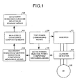
- the induction motor controller computes secondary winding resistance R2 and leakage inductance L corresponding to each of test conditions with at least three types of test power each having a different frequency f, and the secondary winding resistance as well as the leakage inductance for secondary slip frequency in the induction motor required for its actual operation can be computed and measured with high precision by using the following simple rational functions:
- R ⁇ 2 ( f ) ( a ⁇ 1 + a ⁇ 2 ⁇ f 2 ) / 1 + a ⁇ 3 ⁇ f 2
- L ( f ) ( b ⁇ 1 + b ⁇ 2 ⁇ f 2 ) / 1 + b ⁇ 3 ⁇ f 2
- the second computing means computes only factors a1 and b1, and obtains the secondary winding resistance R2 and leakage inductance L each corresponding to a low secondary slip frequency, so that a secondary resistance and a leakage inductance for a secondary slip frequency in the induction motor required for its actual operation can be computed and measured with high precision and within a short time.
- a test power commanding means outputs a command voltage to a polyphase inverter so that the polyphase inventer supplies a specified effective value current to the polyphase induction motor, so that a secondary winding resistance as well as a leakage inductance, each of which changes according to the effective-value current value, corresponding to an effective-value current value for its actual operation can be measured with high precision.
- test power may be of either a three-phase sinusoidal wave or a single-phase sinusoidal wave.
- FIG. 3 is a block diagram showing the induction motor controller for measuring a secondary resistance and a leakage inductance taking into considerations the mutual inductance.
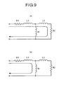
- Fig. 4 is an explanatory view of a single-phase equivalent circuit of the induction motor 102, and Fig. 4(a) shows an L-type equivalent circuit based on assumption that the mutual inductance M is not present, while Fig. 4(b) shows a T-type equivalent circuit where the mutual inductance M is considered.
- a secondary resistance/leakage inductance computing/measuring means for measuring a secondary resistance as well as a leakage inductance for a desired frequency with the L-type equivalent circuit
- an M-considered secondary resistance/leakage inductance computing/measuring means for computing a secondary resistance as well as a leakage inductance taking into considerations the mutual inductance M.
- the voltage increase may be stopped when a peak value of a detected current reaches a value of the ⁇ 2 times a specified current effective value irms, but there is the high probability in this method that the slope may be stopped caused by erroneous detection of a current although the current has not reached a preset value, and for this reason careful attention has to be given to noises or the like when the current is detected.
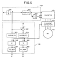
- the command is directly applied to the U phase as described in the section ⁇ Measurement of R2, L by Applying Single-phase Voltage>, and the voltage is multiplied by -1/2 times with the gain 203 and applied to the V phase as well as to the W phase.
- the reference numeral 105a indicates a power computing means, and a phase ⁇ outputted from the integrator 201 is added to a corrected phase ⁇ x with the adder 301.
- This corrected phase ⁇ x is calculated with a current sampling cycle Ts and a delay time T cal in computation as follows.
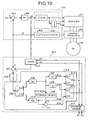
- the reference numeral 506 indicates an estimated gain in the period "a". Output from the estimated gain 506 at this time is a sum (R1a+R2a) of primary resistance and secondary resistance.
- the reference numeral 507 indicates a gain for separating the sum (R1a+R2a) at an appropriate ratio k1 and obtaining the primary resistance R1a. This gain k1 is not less than 0 and not more than 1.
- the reference numeral 508 indicates a gain for obtaining secondary resistance R2a from the sum (R1a+R2a), and the gain is set to 1-k1.
- the reference numeral 509 indicates a storage device for storing therein this (R1a+R2a) at the point of time the period "a" is time-out.
- the voltage estimating device 502 computes primary/secondary leakage inductances L1, L2 and a mutual inductance M among the electrical constants of the induction motor 102 assuming that each thereof is constant, feeds back the values R1a and R2a in the period "a" and the values R1b, R2b in the period "b” as resistance values R1, R2 from the selecting switch 512, 513, outputs an exciting-voltage estimated value vd ⁇ from the voltage estimating device 502, and determines that the resistances values R1, R2 approach the true values when a deviation between the exciting-voltage estimated value vd ⁇ and the exciting voltage command Vd is zero or not more than a specified value.
- the exciting-voltage estimated value vd ⁇ when an exciting-voltage estimated value vd ⁇ is estimated and computed by using electrical constants of the induction motor 102 which are known from the exciting current id at that point of time, the exciting-voltage estimated value vd ⁇ has a difference from an exciting voltage command vd by the difference that the determined electrical constants have.
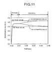
- a true value of an actual primary resistance is 0.532 ⁇ , while a true value of an actual secondary resistance is 0.400 ⁇ , but an appropriate ratio may be put in the period "a".
- the secondary resistance is obtained in the period “b” by estimating the primary resistance and subtracting the estimated primary resistance from the sum obtained in the period "a". The estimation is substantially converged within such a short time as 0.05 sec obtained by summing the period "a" to the period "b".
- the secondary-resistance estimated value is estimated slightly larger in Fig. 11, the value is small enough to resolve shortage of torque at the time of activation of the motor.
- the primary resistance R10 and secondary resistance R20 are obtained by applying a test power such as a single-phase voltage to the induction motor 102 as described in Embodiment 1 only once before the activation thereof, a resistance in the activation thereof is estimated according to Embodiment 2 within a time to some degree that a temperature in winding is not changed, namely substantially the same time, and the primary resistance R11 and secondary resistance R21 are obtained.
Landscapes
- Engineering & Computer Science (AREA)
- Power Engineering (AREA)
- Control Of Ac Motors In General (AREA)
- Tests Of Circuit Breakers, Generators, And Electric Motors (AREA)
Claims (11)
- Unité de commande de moteur à induction pour mesurer des constantes électriques d'un moteur à induction polyphasé (102) en fournissant une puissance de test à ce dernier avec un inverseur polyphasé (101) et pour actionner / commander ledit moteur à induction polyphasé (102) avec ledit inverseur polyphasé (101) en utilisant un résultat de cette mesure pour des paramètres de commande d'actionnement ; ladite unité de commande comprenant :a) un premier moyen de calcul pour calculer une résistance d'enroulement secondaire R2 aussi bien qu'une inductance de fuite L correspondant à chacune des conditions de test avec ladite puissance de test pour au moins trois fréquences différentes f ; etb) un second moyen de calcul ayant une fonction rationnelle incluant une équation quadratique d'une fréquence f avec la résistance d'enroulement secondaire R2 comme dénominateur et l'inductance de fuite L comme numérateur, dans lequel le coefficient du second terme de la fréquence f au moins dans le dénominateur n'est pas zéro, pour obtenir cette fonction rationnelle en substituant la résistance d'enroulement secondaire R2 aussi bien que l'inductance de fuite L correspondant à chacune des conditions de test dans ladite fonction rationnelle, et calculer la résistance d'enroulement secondaire R2 aussi bien que l'inductance de fuite L en substituant une fréquence de glissement souhaitée dans cette fonction rationnelle obtenue.
- Unité de commande de moteur à induction selon la revendication 1, dans laquelle le second moyen de calcul a des fonctions rationnelles comme suit :


- Unité de commande de moteur à induction selon la revendication 2, dans laquelle le second moyen de calcul obtient seulement les facteurs a1 et b1, et calcule une résistance d'enroulement secondaire R2 aussi bien qu'une inductance de fuite L correspondant à une faible fréquence de glissement secondaire.
- Unité de commande de moteur à induction selon la revendication 1, dans laquelle le premier moyen de calcul calcule une première résistance d'enroulement secondaire R2 pour une fréquence spécifiée à l'avance f ; et le second moyen de calcul obtient une deuxième résistance d'enroulement secondaire R2 en substituant ladite fréquence spécifiée à l'avance f dans une fonction rationnelle ayant précédemment été obtenue par ce second moyen de calcul, obtenant une troisième résistance d'enroulement secondaire R2 en substituant une fréquence de glissement souhaitée f dans la fonction rationnelle, et en multipliant cette troisième résistance d'enroulement secondaire R2 par un rapport entre la deuxième résistance d'enroulement secondaire R2 et la première résistance d'enroulement secondaire R2.
- Unité de commande de moteur à induction selon la revendication 1, pour mesurer des constantes électriques d'un moteur à induction polyphasé en fournissant une puissance de test à ce dernier avec un inverseur polyphasé et pour actionner / commander ledit moteur à induction polyphasé avec ledit inverseur polyphasé en utilisant un résultat de cette mesure pour des paramètres de commande d'actionnement ; ladite unité de commande comprenant un moyen de calcul de puissance pour calculer une puissance active P et une puissance réactive Q correspondant à ladite puissance de test d'une fréquence f ; un premier moyen de calcul pour obtenir une résistance secondaire R2d et une inductance de fuite secondaire L2d à partir d'une équation de calcul obtenue avec un circuit équivalent de type L à partir d'une valeur de crête de tension de phase Vp aussi bien qu'une fréquence angulaire primaire w correspondant à ladite fréquence f, ladite puissance active P aussi bien que ladite puissance réactive Q, et une résistance primaire R1 ayant précédemment été mesurée ; et un second moyen de calcul pour obtenir la résistance secondaire R2 et l'inductance de fuite secondaire L en substituant ladite résistance secondaire R2d aussi bien que ladite inductance de fuite secondaire L2d ayant été obtenues par le premier moyen de calcul et une inductance propre secondaire LL2 ayant précédemment été mesurée dans chacune des équations de calcul de la résistance secondaire R2 et de l'inductance de fuite secondaire L ayant respectivement été obtenues par un circuit équivalent de type T.
- Unité de commande de moteur à induction selon la revendication 5, dans laquelle les équations de calcul obtenues par le circuit équivalent de type L sont comme suit :



- Unité de commande de moteur à induction selon la revendication 5, dans laquelle le moyen de calcul de puissance calcule une puissance momentanément active aussi bien qu'une puissance momentanément réactive à partir d'une tension appliquée d'un courant monophasé fourni au moteur à induction polyphasé par l'inverseur polyphasé, et filtre un élément de haute fréquence en provenance de ladite puissance momentanément active aussi bien que de ladite puissance momentanément réactive.
- Unité de commande de moteur à induction selon la revendication 7, dans laquelle le moyen de calcul de puissance filtre un élément de fréquence deux fois aussi élevé que celui de la tension appliquée avec un filtre coupe-bande à partir de ladite puissance momentanément active aussi bien que de ladite puissance momentanément réactive, et filtre également un élément de haute fréquence dépassant ledit élément de fréquence deux fois plus élevé avec un filtre passe-bas.
- Unité de commande de moteur à induction selon la revendication 5, comprenant en outre un moyen de commande de puissance de test pour sortir une tension de commande vers un inverseur polyphasé de sorte que l'inverseur polyphasé fournit un courant de valeur efficace spécifiée au moteur à induction polyphasé.
- Unité de commande de moteur à induction selon la revendication 9, dans laquelle le moyen de commande de puissance de test augmente une tension de commande vers l'inverseur polyphasé à un débit d'élévation spécifié, et arrête d'augmenter ladite tension de commande quand une valeur moyenne d'un temps obtenu par l'élévation au carré d'un courant de valeur efficace fourni au moteur à induction polyphasé par l'inverseur polyphasé selon l'élévation de cette tension de commande est égale à 1/3 du courant de valeur efficace spécifiée ou plus grande.
- Unité de commande de moteur à induction selon la revendication 5, comprenant en outre un moyen de commande de puissance de test pour sortir une tension de commande vers un inverseur polyphasé, dans laquelle le moyen de calcul de puissance calcule une puissance active P aussi bien qu'une puissance réactive Q en corrigeant une phase de ladite tension de commande sur base d'une phase corrigée correspondant à un temps de retard en raison de la mesure et du calcul.
Priority Applications (2)
| Application Number | Priority Date | Filing Date | Title |
|---|---|---|---|
| EP06017163A EP1737121B1 (fr) | 1997-03-11 | 1997-03-11 | Unité de commande de moteur à induction |
| DE69738699T DE69738699D1 (de) | 1997-03-11 | 1997-03-11 | Induktionsmotorsteuerung |
Applications Claiming Priority (1)
| Application Number | Priority Date | Filing Date | Title |
|---|---|---|---|
| PCT/JP1997/000752 WO1998040964A1 (fr) | 1997-03-11 | 1997-03-11 | Dispositif de commande de moteur asynchrone |
Related Child Applications (1)
| Application Number | Title | Priority Date | Filing Date |
|---|---|---|---|
| EP06017163A Division EP1737121B1 (fr) | 1997-03-11 | 1997-03-11 | Unité de commande de moteur à induction |
Publications (3)
| Publication Number | Publication Date |
|---|---|
| EP0899864A1 EP0899864A1 (fr) | 1999-03-03 |
| EP0899864A4 EP0899864A4 (fr) | 2002-10-23 |
| EP0899864B1 true EP0899864B1 (fr) | 2007-02-14 |
Family
ID=14180182
Family Applications (1)
| Application Number | Title | Priority Date | Filing Date |
|---|---|---|---|
| EP97906869A Expired - Lifetime EP0899864B1 (fr) | 1997-03-11 | 1997-03-11 | Dispositif de commande de moteur asynchrone |
Country Status (7)
| Country | Link |
|---|---|
| US (1) | US6066934A (fr) |
| EP (1) | EP0899864B1 (fr) |
| JP (1) | JP3526876B2 (fr) |
| KR (1) | KR100321263B1 (fr) |
| DE (1) | DE69737351T2 (fr) |
| TW (1) | TW479143B (fr) |
| WO (1) | WO1998040964A1 (fr) |
Families Citing this family (25)
| Publication number | Priority date | Publication date | Assignee | Title |
|---|---|---|---|---|
| FR2804254B1 (fr) * | 2000-01-26 | 2002-05-31 | Air Liquide | Procede perfectionne de fourniture d'energie electrique au reseau a l'aide d'un generateur de courant alternatif associe a une turbine |
| KR100371369B1 (ko) * | 2000-08-18 | 2003-02-06 | 엘지산전 주식회사 | 유도 전동기의 벡터 제어 시스템 |
| US6661194B2 (en) | 2002-02-11 | 2003-12-09 | Ford Global Technologies, Llc | Real-time estimation of induction machine parameters using sinusoidal voltage signals |
| KR20030073138A (ko) * | 2002-03-08 | 2003-09-19 | 엘지산전 주식회사 | 유도전동기의 누설 인덕턴스 추정장치 및 방법 |
| AU2004237551B2 (en) | 2003-05-08 | 2007-07-26 | Mitsubishi Denki Kabushiki Kaisha | Method for providing energy saving service, method for deciding specification of electric motor, method for providing compressor version-up service, method for providing energy saving service using drive device for permanent magnet electric motor, compressor exchange method, and freezing/air conditioning device |
| CN100422758C (zh) * | 2003-06-06 | 2008-10-01 | 三菱电机株式会社 | 旋转机的常数测定装置 |
| US7002317B2 (en) * | 2004-02-18 | 2006-02-21 | Honeywell International Inc. | Matched reactance machine power-generation system |
| JP4402600B2 (ja) * | 2005-01-13 | 2010-01-20 | 株式会社日立製作所 | 同期電動機の駆動システム及び同期電動機の駆動方法 |
| FR2884658B1 (fr) * | 2005-04-13 | 2007-05-18 | Schneider Toshiba Inverter | Procede d'ajustement de parametres d'un moteur electrique et variateur de vitesse utilisant un tel procede |
| KR101270538B1 (ko) * | 2006-07-12 | 2013-06-03 | 삼성전자주식회사 | 식기세척기 |
| KR101241354B1 (ko) * | 2006-08-14 | 2013-03-08 | 현대중공업 주식회사 | 고속전철용 추진제어장치의 평지 및 구배에서 기동특성이개선된 벡터제어방법 |
| AU2006347701B2 (en) * | 2006-08-31 | 2010-11-18 | Mitsubishi Electric Corporation | Electric motor driving device, and compressor driving device |
| SE532537C2 (sv) * | 2007-06-12 | 2010-02-16 | Subsee Ab | Anordning och förfarande för off-line testning av en elmotor |
| JP5332321B2 (ja) | 2008-06-04 | 2013-11-06 | パナソニック株式会社 | モータ制御装置 |
| KR20100022145A (ko) * | 2008-08-19 | 2010-03-02 | 삼성전자주식회사 | 세탁기 및 모터의 제어 방법 |
| WO2013080292A1 (fr) * | 2011-11-29 | 2013-06-06 | 三菱電機株式会社 | Dispositif de commande de mécanisme rotatif et procédé de mesure d'inductance de mécanisme rotatif |
| CN104467558B (zh) * | 2013-09-16 | 2017-01-25 | 中山大洋电机股份有限公司 | 一种替换psc电机的ecm电机参数设定方法 |
| JP2015130739A (ja) * | 2014-01-07 | 2015-07-16 | ファナック株式会社 | 磁束制御適用の有無を切り換え可能なモータ制御装置 |
| US9618582B2 (en) | 2014-10-30 | 2017-04-11 | Delphi Technologies, Inc. | System and method of electric motor fault detection |
| JP6717791B2 (ja) * | 2017-09-28 | 2020-07-08 | ファナック株式会社 | パラメータ決定支援装置 |
| JP7057723B2 (ja) * | 2018-06-22 | 2022-04-20 | オークマ株式会社 | 位置制御装置 |
| CN112912739B (zh) | 2018-06-29 | 2024-06-11 | 布鲁萨电子公司 | 用于测量当前作用功率的初级测量装置 |
| JP2021002897A (ja) * | 2019-06-19 | 2021-01-07 | 東芝三菱電機産業システム株式会社 | 電動機制御装置、電動機システム、回転子巻線二次抵抗値の演算方法、回転子巻線温度推定方法 |
| CN112345839B (zh) * | 2019-08-07 | 2021-10-08 | 株洲中车时代电气股份有限公司 | 一种变压器次边漏抗的在线辨识方法、装置和电路 |
| CN116633126B (zh) * | 2023-07-24 | 2023-10-17 | 成都希望森兰智能制造有限公司 | 一种无网压传感器的变频器老化系统功率因数控制方法 |
Family Cites Families (19)
| Publication number | Priority date | Publication date | Assignee | Title |
|---|---|---|---|---|
| US4204425A (en) * | 1978-06-29 | 1980-05-27 | Westinghouse Electric Corp. | Method of testing induction motors |
| JPS6016184A (ja) * | 1983-07-06 | 1985-01-26 | Mitsubishi Electric Corp | エレベ−タの制御装置 |
| US4670698A (en) * | 1983-12-02 | 1987-06-02 | Imec Corporation | Adaptive induction motor controller |
| JPS61180592A (ja) * | 1985-02-05 | 1986-08-13 | Mitsubishi Electric Corp | 査導電動機の制御装置 |
| JPH0783640B2 (ja) * | 1985-11-13 | 1995-09-06 | 株式会社日立製作所 | すべり周波数演算器の自動設定法 |
| US4801877A (en) * | 1986-05-06 | 1989-01-31 | General Electric Company | Method and apparatus for testing dynamoelectric machine rotors |
| US4789834A (en) * | 1986-12-22 | 1988-12-06 | General Electric Company | Method and apparatus for testing of induction motor overload protection device |
| JPS63245290A (ja) * | 1987-03-31 | 1988-10-12 | Toshiba Corp | 誘導機の制御装置 |
| JP2640159B2 (ja) * | 1990-04-27 | 1997-08-13 | 富士写真フイルム株式会社 | 電子写真式製版用印刷原版 |
| JPH04285878A (ja) * | 1991-03-14 | 1992-10-09 | Meidensha Corp | リニア誘導モータの特性算定方式 |
| JP2505325B2 (ja) * | 1991-06-10 | 1996-06-05 | 東洋電機製造株式会社 | 誘導電動機の抵抗推定起動装置 |
| JP3029734B2 (ja) * | 1992-04-23 | 2000-04-04 | 株式会社東芝 | 誘導電動機制御装置 |
| JP3284602B2 (ja) * | 1992-09-16 | 2002-05-20 | 株式会社日立製作所 | 交流電動機の定数測定方法及び制御装置 |
| US5388052A (en) * | 1993-03-31 | 1995-02-07 | Otis Elevator Company | Method of operating an induction motor |
| JP2759932B2 (ja) * | 1993-09-29 | 1998-05-28 | 東洋電機製造株式会社 | 定数測定設定機能付きインバータ装置 |
| JP3092839B2 (ja) * | 1994-04-26 | 2000-09-25 | 東洋電機製造株式会社 | 定数測定設定機能付きインバータ装置 |
| JP2850096B2 (ja) * | 1994-05-30 | 1999-01-27 | 東洋電機製造株式会社 | 定数測定設定機能付きインバータ制御方法 |
| JP3638030B2 (ja) * | 1994-11-21 | 2005-04-13 | 東洋電機製造株式会社 | 定数測定設定機能付きインバ−タの制御方法 |
| JP3065517B2 (ja) * | 1995-10-18 | 2000-07-17 | 東洋電機製造株式会社 | 多相交流より直流を得る電圧形コンバータの制御装置 |
-
1997
- 1997-03-11 EP EP97906869A patent/EP0899864B1/fr not_active Expired - Lifetime
- 1997-03-11 DE DE69737351T patent/DE69737351T2/de not_active Expired - Lifetime
- 1997-03-11 WO PCT/JP1997/000752 patent/WO1998040964A1/fr not_active Ceased
- 1997-03-11 JP JP53940998A patent/JP3526876B2/ja not_active Expired - Lifetime
- 1997-03-11 US US09/171,569 patent/US6066934A/en not_active Expired - Lifetime
- 1997-03-11 KR KR1019980708813A patent/KR100321263B1/ko not_active Expired - Lifetime
- 1997-03-21 TW TW086103555A patent/TW479143B/zh not_active IP Right Cessation
Also Published As
| Publication number | Publication date |
|---|---|
| WO1998040964A1 (fr) | 1998-09-17 |
| US6066934A (en) | 2000-05-23 |
| TW479143B (en) | 2002-03-11 |
| KR100321263B1 (ko) | 2002-06-20 |
| HK1016361A1 (en) | 1999-10-29 |
| EP0899864A1 (fr) | 1999-03-03 |
| EP0899864A4 (fr) | 2002-10-23 |
| KR20000010712A (ko) | 2000-02-25 |
| DE69737351T2 (de) | 2007-10-31 |
| DE69737351D1 (de) | 2007-03-29 |
| JP3526876B2 (ja) | 2004-05-17 |
Similar Documents
| Publication | Publication Date | Title |
|---|---|---|
| EP0899864B1 (fr) | Dispositif de commande de moteur asynchrone | |
| EP1312932B1 (fr) | Procede de mesure de la constante d'un moteur a induction | |
| US6831439B2 (en) | Apparatus for measuring magnetic flux of synchronous reluctance motor and sensorless control system for the same motor | |
| US6462492B1 (en) | Position-sensorless controlling method of synchronous motor | |
| JPWO1998040964A1 (ja) | 誘導電動機制御装置 | |
| US7187155B2 (en) | Leakage inductance saturation compensation for a slip control technique of a motor drive | |
| US8860341B2 (en) | Power regeneration device and power conversion device | |
| US7199548B2 (en) | Drive control apparatus and method of alternating current motor | |
| JP2708408B2 (ja) | 電圧制御形ベクトル制御インバータの制御装置 | |
| EP1035645B1 (fr) | Dispositif de commande de moteur asynchrone | |
| US8106621B2 (en) | Control device for induction motor | |
| KR19990086188A (ko) | 유도 전동기에서의 고정자 및 회전자 저항값 추정방법 | |
| KR100400595B1 (ko) | 유도 전동기의 파라미터 추정장치 및 방법 | |
| EP0083945B1 (fr) | Procédé et appareil pour régler des moteurs à induction | |
| US20020195986A1 (en) | Method and apparatus for connecting a converter to an asynchronous machine | |
| KR100563225B1 (ko) | 유도전동기의제어장치 | |
| JP3771239B2 (ja) | 誘導電動機制御装置 | |
| EP1737121B1 (fr) | Unité de commande de moteur à induction | |
| HK1016361B (en) | Induction motor controller | |
| JP3019653B2 (ja) | 交流電動機の制御装置及び交流電動機の定数測定方法 | |
| HK1098593A1 (en) | Induction motor controller | |
| HK1098593B (en) | Induction motor controller | |
| JP2850096B2 (ja) | 定数測定設定機能付きインバータ制御方法 | |
| JP2005020817A (ja) | 速度センサレスベクトル制御方法および装置 | |
| JP3299416B2 (ja) | 誘導電動機のベクトル制御方法 |
Legal Events
| Date | Code | Title | Description |
|---|---|---|---|
| PUAI | Public reference made under article 153(3) epc to a published international application that has entered the european phase |
Free format text: ORIGINAL CODE: 0009012 |
|
| 17P | Request for examination filed |
Effective date: 19981111 |
|
| AK | Designated contracting states |
Kind code of ref document: A1 Designated state(s): DE GB |
|
| RIC1 | Information provided on ipc code assigned before grant |
Free format text: 7H 02P 7/63 A, 7H 02P 21/00 B, 7G 01R 31/34 B |
|
| A4 | Supplementary search report drawn up and despatched |
Effective date: 20020910 |
|
| AK | Designated contracting states |
Kind code of ref document: A4 Designated state(s): DE GB |
|
| 17Q | First examination report despatched |
Effective date: 20050331 |
|
| RAP1 | Party data changed (applicant data changed or rights of an application transferred) |
Owner name: MITSUBISHI DENKI KABUSHIKI KAISHA |
|
| RIC1 | Information provided on ipc code assigned before grant |
Ipc: G01R 31/34 20060101ALI20060531BHEP Ipc: H02P 27/06 20060101ALI20060531BHEP Ipc: H02P 21/14 20060101AFI20060531BHEP |
|
| GRAP | Despatch of communication of intention to grant a patent |
Free format text: ORIGINAL CODE: EPIDOSNIGR1 |
|
| RIN1 | Information on inventor provided before grant (corrected) |
Inventor name: SHIRAISHI, YASUHIRO,MITSUBISHI DENKI K.K. Inventor name: IMANAKA, AKIRA,MITSUBISHI DENKI K.K. Inventor name: NAGANO, TETUAKI,MITSUBISHI DENKI K.K. Inventor name: KAITANI, TOSHIYUKI,MITSUBISHI DENKI K.K. |
|
| GRAS | Grant fee paid |
Free format text: ORIGINAL CODE: EPIDOSNIGR3 |
|
| GRAA | (expected) grant |
Free format text: ORIGINAL CODE: 0009210 |
|
| AK | Designated contracting states |
Kind code of ref document: B1 Designated state(s): DE GB |
|
| REG | Reference to a national code |
Ref country code: GB Ref legal event code: FG4D |
|
| REG | Reference to a national code |
Ref country code: GB Ref legal event code: 727 |
|
| REF | Corresponds to: |
Ref document number: 69737351 Country of ref document: DE Date of ref document: 20070329 Kind code of ref document: P |
|
| REG | Reference to a national code |
Ref country code: HK Ref legal event code: GR Ref document number: 1016361 Country of ref document: HK |
|
| PLBE | No opposition filed within time limit |
Free format text: ORIGINAL CODE: 0009261 |
|
| STAA | Information on the status of an ep patent application or granted ep patent |
Free format text: STATUS: NO OPPOSITION FILED WITHIN TIME LIMIT |
|
| 26N | No opposition filed |
Effective date: 20071115 |
|
| REG | Reference to a national code |
Ref country code: GB Ref legal event code: 727A |
|
| REG | Reference to a national code |
Ref country code: GB Ref legal event code: S27 |
|
| REG | Reference to a national code |
Ref country code: GB Ref legal event code: 746 Effective date: 20090330 |
|
| PGFP | Annual fee paid to national office [announced via postgrant information from national office to epo] |
Ref country code: DE Payment date: 20160308 Year of fee payment: 20 |
|
| PGFP | Annual fee paid to national office [announced via postgrant information from national office to epo] |
Ref country code: GB Payment date: 20160309 Year of fee payment: 20 |
|
| REG | Reference to a national code |
Ref country code: DE Ref legal event code: R071 Ref document number: 69737351 Country of ref document: DE |
|
| REG | Reference to a national code |
Ref country code: GB Ref legal event code: PE20 Expiry date: 20170310 |
|
| PG25 | Lapsed in a contracting state [announced via postgrant information from national office to epo] |
Ref country code: GB Free format text: LAPSE BECAUSE OF EXPIRATION OF PROTECTION Effective date: 20170310 |