EP0899894B1 - Récepteur avec antenne intelligente et procédé de réception de signaux - Google Patents
Récepteur avec antenne intelligente et procédé de réception de signaux Download PDFInfo
- Publication number
- EP0899894B1 EP0899894B1 EP98116258A EP98116258A EP0899894B1 EP 0899894 B1 EP0899894 B1 EP 0899894B1 EP 98116258 A EP98116258 A EP 98116258A EP 98116258 A EP98116258 A EP 98116258A EP 0899894 B1 EP0899894 B1 EP 0899894B1
- Authority
- EP
- European Patent Office
- Prior art keywords
- signal
- generating
- array output
- adaptive
- pseudo noise
- Prior art date
- Legal status (The legal status is an assumption and is not a legal conclusion. Google has not performed a legal analysis and makes no representation as to the accuracy of the status listed.)
- Expired - Lifetime
Links
Images

Classifications
-
- H—ELECTRICITY
- H04—ELECTRIC COMMUNICATION TECHNIQUE
- H04B—TRANSMISSION
- H04B1/00—Details of transmission systems, not covered by a single one of groups H04B3/00 - H04B13/00; Details of transmission systems not characterised by the medium used for transmission
- H04B1/76—Pilot transmitters or receivers for control of transmission or for equalising
-
- H—ELECTRICITY
- H04—ELECTRIC COMMUNICATION TECHNIQUE
- H04B—TRANSMISSION
- H04B7/00—Radio transmission systems, i.e. using radiation field
- H04B7/02—Diversity systems; Multi-antenna system, i.e. transmission or reception using multiple antennas
- H04B7/04—Diversity systems; Multi-antenna system, i.e. transmission or reception using multiple antennas using two or more spaced independent antennas
- H04B7/08—Diversity systems; Multi-antenna system, i.e. transmission or reception using multiple antennas using two or more spaced independent antennas at the receiving station
- H04B7/0837—Diversity systems; Multi-antenna system, i.e. transmission or reception using multiple antennas using two or more spaced independent antennas at the receiving station using pre-detection combining
- H04B7/0842—Weighted combining
- H04B7/0848—Joint weighting
- H04B7/0851—Joint weighting using training sequences or error signal
-
- H—ELECTRICITY
- H04—ELECTRIC COMMUNICATION TECHNIQUE
- H04B—TRANSMISSION
- H04B1/00—Details of transmission systems, not covered by a single one of groups H04B3/00 - H04B13/00; Details of transmission systems not characterised by the medium used for transmission
- H04B1/69—Spread spectrum techniques
- H04B1/707—Spread spectrum techniques using direct sequence modulation
-
- H—ELECTRICITY
- H04—ELECTRIC COMMUNICATION TECHNIQUE
- H04J—MULTIPLEX COMMUNICATION
- H04J13/00—Code division multiplex systems
- H04J13/0007—Code type
- H04J13/0022—PN, e.g. Kronecker
Definitions
- the invention relates to a mobile communication system, and more particularly, to a smart antenna receiver in a CDMA (Code Division Multiple Access) communication system and to a signal receiving method therefor.
- CDMA Code Division Multiple Access
- a smart antenna receiver using an adaptive antenna array technology automatically adjusts an antenna to the optimal direction according to information obtained by receiving an input signal by respective elements.
- a conventional smart antenna receiver is comprised of a multiplier circuit 110 including a plurality of multipliers 110-1,...,110-n formed correspondingly to an adaptive antenna array, a summer 120, and an adaptive processor 130 for adjusting adaptive weights.
- array input vector signals X1,...Xn received from a plurality of antennas of an adaptive array are respectively applied to the multipliers 110-1,...,110-n where they are multiplied by weights W1,...,Wn of complex numbers adjusted adaptively by the adaptive processor 130.
- the output signals generated from the multipliers 110-1,..., 110-n are supplied to the summer 120 where they are summed up to generate an array output y.
- the gain is increased in the direction of a received signal which includes the desired information whereas a null is formed in the direction of a received interference signal, so that a signal can be spatially selectively received.
- the circuit shown in FIG. 1 is called a spatial filter.
- the spatial filter increases the capacity of a system by reducing the interference between the same channels in a CDMA mobile communication system.
- the adaptive processor 130 of the conventional antenna receiver adjusts the adaptive weights W1,...,Wn only using the array input vector signals X1,...,Xn and the array output y.
- the adaptive processor 130 carries out complicated calculation processes of searching for the direction of a signal source by calculating an optimal weight, for including those for obtaining an autocorrelation matrix of a received vector signal, and for obtaining an inverse matrix and a unique vector of the autocorrelation matrix.
- the invention is advantageous in making use of the information about the differences between the desired signal and the interference signal in a more effective way than conventional receivers and methods do. Moreover, it is advantageous to use the pilot signal in the receiver and the method according to the invention, since the pilot signal is also used to coherently detect data in a reverse link of the CDMA system
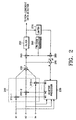
- a smart antenna receiver includes a multiplier circuit 210, a summer 220, an adaptive processor 230, multipliers 240 and 280, a data bandwidth filter 250, a PN code generator 260, a limiter 270, and a subtracter 290.
- a plurality of linearly or circularly arranged antennas receive radio signals X1,...,Xn.
- the multiplier circuit 210 includes a plurality of multipliers 210-1,...,210-n connected respectively to the antennas and multiplies the radio signals X1,...,Xn by adaptive weights W1,...,Wn.
- the summer 220 sums the outputs of the multipliers 210-1,...,210-n to generate an array output signal y.
- the adaptive processor 230 adjusts the adaptive weights W1,...,Wn by performing an adaptive algorithm using an error signal ⁇ generated from the subtracter 290 and using the radio signals X1,...,Xn.
- the PN code generator 260 generates a pilot PN code from a received pilot signal in the reverse link.
- the multiplier 240 multiplies the pilot PN code by the array output signal y generated from the summer 220.
- a reference signal generating loop including the filter 250, the limiter 270 and the multiplier 280 generates a reference signal y d used for the adaptive algorithm of the adaptive processor 230.
- the subtracter 290 generates the error signat ⁇ corresponding to the in phase or time aligned difference between the reference signal y d and the array output signal y.
- an adaptive weight W is adjusted such that a main robe of a receiving beam pattern is toward the desired signal and a null of the receiving beam pattern is toward the interference signal.
- the adaptive weight comes to converge upon an optimal adaptive weight for minimizing a mean square error (MSE) through repeated weight updating.
- MSE mean square error
- the radio signals X1,...,Xn received at the respective antennas are supplied to the multipliers 210-1,...,210-n where they are multiplied by the adaptive weights W1,...,Wn provided from the adaptive processor 230.
- the signals produced from the multiplies 210-1,...,210-n are then applied to the summer 220 to generate the array output signal y.
- the array output signal y is applied to the subtracter 290 and the multiplier 240.
- the array output signal y applied to the multiplier 240 is multiplied by the pilot PN code generated from the PN code generator 260.
- the pilot PN code is the same as the PN code which has been multiplied by the signal of the desired user.
- the desired signal is despread by the multiplier 240 and its bandwidth is reduced to a data bandwidth.
- An interference component remains in a spread bandwidth. While the output of the multiplier 240 passes through the data bandwidth filter 250, the desired signal remains and the interference component except an intermediate bandwidth is eliminated.
- the output of the filter 250 is applied to limiter 270 for adjusting the amplitude of the reference signal y d .
- the output of the limiter 270 is applied to the multiplier 280 where it is multiplied by the pilot PN code and re-spread.
- the reference signal y d is generated.
- the array output signal y and the reference signal y d generated respectively from the summer 220 and the multiplier 280 are then applied to the subtracter 290 where the error signal ⁇ corresponding to the difference therebetween is generated.
- the error signal e is applied to the adaptive processor 230 so as to obtain the adaptive weight W by the above equation (1) together with the data vector x of the radio signals X1,...,Xn.
- the discrete time k such as an adaptive period and the scalar constant ⁇ needed to obtain the adaptive weight W by the equation (1) are set constant.
- the smart antenna receiver uses the reference signal generating loop using the pilot signal and the adaptive processor which applies the LMS algorithm, the amount of calculation can be greatly reduced.
Landscapes
- Engineering & Computer Science (AREA)
- Computer Networks & Wireless Communication (AREA)
- Signal Processing (AREA)
- Radio Transmission System (AREA)
- Mobile Radio Communication Systems (AREA)
- Variable-Direction Aerials And Aerial Arrays (AREA)
Claims (18)
- Récepteur à antenne intelligent utilisant un signal pilote dans une station de base d'un système de communication mobile à accès multiple à division de code, comprenant :un processeur adaptatif (230) pour générer des poids adaptatifs (W1, W2, Wn) à l'aide de signaux de radio (X1, X2, Xn) reçus respectivement par une pluralité d'antennes ;une unité de pondération (210-1, 210-2, 210-n) pour pondérer lesdits signaux de radio à l'aide desdits poids adaptatifs ; etun générateur de signal de sortie de groupement (220) pour recevoir lesdits signaux pondérés et pour générer un signal de sortie de groupement (y) à partir de ceux-ci ;un générateur de code de pseudo-bruit (260) pour générer un code de pseudo-bruit qui est détecté à partir dudit signal pilote et qui a été utilisé dans un émetteur ;un générateur de signal dé-étalé (240) pour générer un signal dé-étalé à l'aide dudit signal de sortie de groupement et dudit code de pseudo-bruit ;une unité d'élimination (250) pour éliminer substantiellement les composantes d'interférence dudit signal dé-étalé ;un générateur de signal ré-étalé (280) pour générer un signal de référence ré-étalé (yd) à l'aide du signal délivré en sortie de ladite unité d'élimination et dudit code de pseudo-bruit ; etun générateur de signal d'erreur (290) pour générer un signal d'erreur (e) indiquant une différence entre ledit signal de référence et ledit signal de sortie de groupement, ledit signal d'erreur étant entré sur le processeur adaptatif, le processeur adaptatif utilisant ledit signal d'erreur et lesdits signaux de radio pour générer des poids adaptatifs optimaux.
- Récepteur selon la revendication 1, caractérisé en ce que l'unité de pondération comprend une pluralité de multiplicateurs pour multiplier lesdits signaux de radio par lesdits poids adaptatifs.
- Récepteur selon la revendication 1 ou 2, caractérisé en ce que ledit générateur de signal de sortie de groupement comprend un totaliseur pour totaliser les signaux pondérés.
- Récepteur selon l'une des revendications 1 à 3, caractérisé en ce que le générateur de signal dé-étalé comprend un multiplicateur pour multiplier ledit signal de sortie de groupement par ledit code de pseudo-bruit.
- Récepteur selon l'une des revendications 1 à 4, caractérisé en ce que ladite unité d'élimination comprend un filtre de largeur de bande de données pour filtrer ledit signal dé-étalé.
- Récepteur selon l'une des revendications 1 à 5, caractérisé en ce que le générateur de signal ré-étalé comprend un multiplicateur pour multiplier la sortie de ladite unité d'élimination par ledit code de pseudo-bruit.
- Récepteur selon l'une des revendications 1 à 6, caractérisé en ce que ledit générateur de signal d'erreur comprend un soustracteur pour calculer la différence entre ledit signal de référence et ledit signal de sortie de groupement.
- Récepteur selon l'une des revendications 1 à 7, caractérisé de plus par :un limiteur (270) pour ajuster l'amplitude du signal délivré en sortie de ladite unité d'élimination de pour délivrer au générateur de signal ré-étalé ladite amplitude ajustée.
- Récepteur selon l'une des revendications 1 à 8, caractérisé en ce que ledit processeur adaptatif est configuré de façon à générer lesdits poids adaptatifs optimaux W au moyen de l'équation suivante :
- Procédé de réception de signal utilisant un signal pilote dans un système de communication mobile à accès multiple à division de code, le procédé comprenant les étapes consistant à :générer des poids adaptatifs (W1, W2, Wn) en utilisant des signaux de radio (X1, X2, Xn) reçus sur une pluralité d'antennes ;pondérer lesdits signaux de radio à l'aide desdits poids adaptatifs ; etgénérer un signal de sortie de groupement (y) en utilisant lesdits signaux pondérés ;générer un signal dé-étalé en utilisant ledit signal de sortie de groupement et un code de pseudo-bruit détecté à partir dudit signal pilote ;éliminer substantiellement les composantes d'interférence dudit signal dé-étalé ;générer un signal de référence ré-étalé (yd) en utilisant le signal dont on a éliminé les composantes d'interférence et ledit code de pseudo-bruit ; etgénérer un signal d'erreur (ε) indiquant une différence entre ledit signal de référence et ledit signal de sortie de groupement et utiliser ledit signal d'erreur et lesdits signaux de radio pour générer des poids adaptatifs optimaux.
- Procédé selon la revendication 10, caractérisé en ce que l'étape de pondération comprend la multiplication desdits signaux de radio par lesdits poids adaptatifs.
- Procédé selon la revendication 10 ou 11, caractérisé en ce que l'étape de génération d'un signal de sortie de groupement comprend la totalisation des signaux pondérés.
- Procédé selon l'une des revendications 10 à 12, caractérisé en ce que l'étape de génération d'un signal dé-étalé comprend la multiplication dudit signal de sortie de groupement par ledit code de pseudo-bruit.
- Procédé selon l'une des revendications 10 à 13, caractérisé en ce que l'étape d'élimination comprend le filtrage dudit signal dé-étalé.
- Procédé selon l'une des revendications 10 à 14, caractérisé en ce que l'étape de génération d'un signal de référence ré-étalé comprend la multiplication du signal dont on a éliminé les composantes d'interférence par ledit code de pseudo-bruit.
- Procédé selon l'une des revendications 10 à 15, caractérisé en ce que l'étape de génération du signal d'erreur comprend une étape de soustraction du calcul de la différence entre ledit signal de référence et ledit signal de sortie de groupement.
- Procédé selon l'une des revendications 10 à 16, caractérisé de plus par l'étape consistant à ajuster l'amplitude du signal dont on a éliminé les composantes d'interférence et à utiliser ladite amplitude ajustée pour générer le signal de référence ré-étalé.
- Procédé selon l'une des revendications 10 à 17, caractérisé en ce que l'étape de génération de poids adaptatifs optimaux W utilise l'équation suivante :
Applications Claiming Priority (2)
| Application Number | Priority Date | Filing Date | Title |
|---|---|---|---|
| KR9743738 | 1997-08-30 | ||
| KR1019970043738A KR100239177B1 (ko) | 1997-08-30 | 1997-08-30 | 씨디엠에이 이동통신시스템에서 파일럿 신호를 이용한 스마트안테나 수신장치 및 방법 |
Publications (3)
| Publication Number | Publication Date |
|---|---|
| EP0899894A2 EP0899894A2 (fr) | 1999-03-03 |
| EP0899894A3 EP0899894A3 (fr) | 1999-03-10 |
| EP0899894B1 true EP0899894B1 (fr) | 2004-04-21 |
Family
ID=19519856
Family Applications (1)
| Application Number | Title | Priority Date | Filing Date |
|---|---|---|---|
| EP98116258A Expired - Lifetime EP0899894B1 (fr) | 1997-08-30 | 1998-08-28 | Récepteur avec antenne intelligente et procédé de réception de signaux |
Country Status (5)
| Country | Link |
|---|---|
| US (1) | US6353643B1 (fr) |
| EP (1) | EP0899894B1 (fr) |
| KR (1) | KR100239177B1 (fr) |
| CN (1) | CN1135874C (fr) |
| DE (1) | DE69823288T2 (fr) |
Families Citing this family (46)
| Publication number | Priority date | Publication date | Assignee | Title |
|---|---|---|---|---|
| JP3465739B2 (ja) | 1998-04-07 | 2003-11-10 | 日本電気株式会社 | Cdma適応アンテナ受信装置及び通信システム |
| US6989797B2 (en) | 1998-09-21 | 2006-01-24 | Ipr Licensing, Inc. | Adaptive antenna for use in wireless communication systems |
| US6404386B1 (en) * | 1998-09-21 | 2002-06-11 | Tantivy Communications, Inc. | Adaptive antenna for use in same frequency networks |
| US6100843A (en) | 1998-09-21 | 2000-08-08 | Tantivy Communications Inc. | Adaptive antenna for use in same frequency networks |
| FR2788179B1 (fr) * | 1998-12-31 | 2003-06-20 | Cit Alcatel | Satellite a couverture omnidirectionnelle |
| US6141567A (en) * | 1999-06-07 | 2000-10-31 | Arraycomm, Inc. | Apparatus and method for beamforming in a changing-interference environment |
| CN1118200C (zh) * | 1999-08-10 | 2003-08-13 | 信息产业部电信科学技术研究院 | 基于智能天线和干扰抵销的基带处理方法 |
| CN1118201C (zh) | 1999-08-11 | 2003-08-13 | 信息产业部电信科学技术研究院 | 一种基于智能天线的干扰抵销方法 |
| US6115406A (en) | 1999-09-10 | 2000-09-05 | Interdigital Technology Corporation | Transmission using an antenna array in a CDMA communication system |
| US6278726B1 (en) | 1999-09-10 | 2001-08-21 | Interdigital Technology Corporation | Interference cancellation in a spread spectrum communication system |
| KR100689398B1 (ko) * | 1999-10-09 | 2007-03-08 | 삼성전자주식회사 | 이동통신시스템에서 폐루프 송신 안테나 다이버시티 장치 및 방법 |
| KR100625451B1 (ko) * | 1999-12-18 | 2006-09-18 | 주식회사 케이티 | 스마트 안테나와 간섭제거기의 결합장치에서의 간섭신호제거방법 |
| US7289570B2 (en) * | 2000-04-10 | 2007-10-30 | Texas Instruments Incorporated | Wireless communications |
| KR100734347B1 (ko) * | 2000-09-01 | 2007-07-03 | 엘지전자 주식회사 | 안테나 어레이를 이용한 cdma 시스템에서의 간섭신호제거 방법 |
| US6404803B1 (en) * | 2000-10-24 | 2002-06-11 | Neoreach, Inc. | PN code acquisition with adaptive antenna array and adaptive threshold for CDMA wireless communications |
| SG104931A1 (en) * | 2000-11-10 | 2004-07-30 | Sony Electronics Singapore Pte | Multiple-user cdma wireless communication system |
| US7181162B2 (en) * | 2000-12-12 | 2007-02-20 | The Directv Group, Inc. | Communication system using multiple link terminals |
| US6952580B2 (en) * | 2000-12-12 | 2005-10-04 | The Directv Group, Inc. | Multiple link internet protocol mobile communications system and method therefor |
| US20020073437A1 (en) * | 2000-12-12 | 2002-06-13 | Hughes Electronics Corporation | Television distribution system using multiple links |
| US7103317B2 (en) * | 2000-12-12 | 2006-09-05 | The Directv Group, Inc. | Communication system using multiple link terminals for aircraft |
| US7187949B2 (en) * | 2001-01-19 | 2007-03-06 | The Directv Group, Inc. | Multiple basestation communication system having adaptive antennas |
| US8396513B2 (en) * | 2001-01-19 | 2013-03-12 | The Directv Group, Inc. | Communication system for mobile users using adaptive antenna |
| US7809403B2 (en) * | 2001-01-19 | 2010-10-05 | The Directv Group, Inc. | Stratospheric platforms communication system using adaptive antennas |
| US7068616B2 (en) * | 2001-02-05 | 2006-06-27 | The Directv Group, Inc. | Multiple dynamic connectivity for satellite communications systems |
| KR100525785B1 (ko) * | 2001-06-15 | 2005-11-03 | 엘지전자 주식회사 | 이미지 화소 필터링 방법 |
| BG105671A (en) * | 2001-07-04 | 2003-02-28 | Skygate International Technology N.V. | Method and system for radio communications |
| KR20030030590A (ko) | 2001-10-11 | 2003-04-18 | 주식회사 세스텍 | 스마트 안테나 시스템에서 심볼 레이트로 웨이팅하는핑거와, 그를 이용한 복조 장치 및 방법 |
| KR20030031385A (ko) * | 2001-10-15 | 2003-04-21 | 주식회사 세스텍 | 스마트 안테나 시스템에서 칩 레이트로 웨이팅하는핑거와, 그를 이용한 복조 장치 및 방법 |
| KR20030033192A (ko) | 2001-10-18 | 2003-05-01 | 주식회사 세스텍 | 스마트 안테나 시스템에서 심볼레이트와 칩레이트를혼용하여 웨이팅하는 핑거와, 그를 이용한 복조 장치 및방법 |
| KR100447621B1 (ko) * | 2001-12-18 | 2004-09-07 | (주)텔레시스테크놀로지 | 스마트 안테나의 가중치 처리 방법 |
| US7272167B2 (en) * | 2002-02-06 | 2007-09-18 | Neoreach, Inc. | PN code chip time tracking with smart antenna |
| US7327800B2 (en) | 2002-05-24 | 2008-02-05 | Vecima Networks Inc. | System and method for data detection in wireless communication systems |
| KR20040046498A (ko) * | 2002-11-27 | 2004-06-05 | 엘지전자 주식회사 | 기지국 스마트 안테나의 개선된 빔형성 장치 및 그 운용방법 |
| KR100513598B1 (ko) * | 2002-11-27 | 2005-09-09 | 한국전자통신연구원 | 스마트 안테나 수신 시스템에서의 적응 빔형성을 위한정규화 장치 |
| KR20040046499A (ko) * | 2002-11-27 | 2004-06-05 | 엘지전자 주식회사 | 기지국 스마트 안테나의 개선된 빔형성 방법 |
| US7362267B2 (en) * | 2002-12-31 | 2008-04-22 | Zte Corporation | Smart antenna, method and apparatus for adaptive beam forming |
| US7372453B2 (en) * | 2003-01-17 | 2008-05-13 | Jacob Adam Blish | Foot operated computer mouse |
| US6975837B1 (en) | 2003-01-21 | 2005-12-13 | The Directv Group, Inc. | Method and apparatus for reducing interference between terrestrially-based and space-based broadcast systems |
| US7327795B2 (en) | 2003-03-31 | 2008-02-05 | Vecima Networks Inc. | System and method for wireless communication systems |
| US7002897B2 (en) * | 2003-04-28 | 2006-02-21 | Solarflare Communications, Inc. | Multiple channel interference cancellation |
| KR100965721B1 (ko) * | 2003-06-30 | 2010-06-24 | 삼성전자주식회사 | 적응 안테나 어레이 방식을 사용하는 이동 통신 시스템에서 데이터 수신 장치 및 방법 |
| KR100933147B1 (ko) * | 2003-08-07 | 2009-12-21 | 삼성전자주식회사 | 적응 안테나 어레이 방식을 사용하는 이동 통신 시스템에서 신호 수신 장치 및 방법 |
| US20060006707A1 (en) * | 2004-06-30 | 2006-01-12 | Lin A P | Seat post assembly for a bicycle |
| US7702000B1 (en) * | 2005-02-10 | 2010-04-20 | Motia Inc. | Method and system for weight generation in an adaptive array with spread spectrum |
| KR101292814B1 (ko) * | 2005-09-28 | 2013-08-02 | 한국전자통신연구원 | 공간 필터링된 수신 신호들의 최고 비율 조합 방법 및 이를위한 장치 |
| KR100776978B1 (ko) * | 2006-09-30 | 2007-11-21 | 전자부품연구원 | 간섭에러 보정 초광대역 통신 송수신 장치, 송신방법 및수신방법 |
Family Cites Families (5)
| Publication number | Priority date | Publication date | Assignee | Title |
|---|---|---|---|---|
| US5218619A (en) * | 1990-12-17 | 1993-06-08 | Ericsson Ge Mobile Communications Holding, Inc. | CDMA subtractive demodulation |
| GB2268371B (en) * | 1992-04-10 | 1995-09-20 | Roke Manor Research | Radio communication systems |
| JP3143247B2 (ja) * | 1993-01-11 | 2001-03-07 | 沖電気工業株式会社 | 符号分割多元接続復調装置 |
| CN1092431C (zh) * | 1995-11-29 | 2002-10-09 | Ntt移动通信网株式会社 | 分集接收机及其控制方法 |
| US5923700A (en) * | 1997-02-24 | 1999-07-13 | At & T Wireless | Adaptive weight update method and system for a discrete multitone spread spectrum communications system |
-
1997
- 1997-08-30 KR KR1019970043738A patent/KR100239177B1/ko not_active Expired - Fee Related
-
1998
- 1998-08-28 EP EP98116258A patent/EP0899894B1/fr not_active Expired - Lifetime
- 1998-08-28 DE DE69823288T patent/DE69823288T2/de not_active Expired - Fee Related
- 1998-08-30 CN CNB981198309A patent/CN1135874C/zh not_active Expired - Fee Related
- 1998-08-31 US US09/143,811 patent/US6353643B1/en not_active Expired - Lifetime
Also Published As
| Publication number | Publication date |
|---|---|
| EP0899894A2 (fr) | 1999-03-03 |
| US6353643B1 (en) | 2002-03-05 |
| CN1135874C (zh) | 2004-01-21 |
| EP0899894A3 (fr) | 1999-03-10 |
| KR19990020278A (ko) | 1999-03-25 |
| DE69823288T2 (de) | 2004-08-26 |
| KR100239177B1 (ko) | 2000-01-15 |
| DE69823288D1 (de) | 2004-05-27 |
| CN1220562A (zh) | 1999-06-23 |
Similar Documents
| Publication | Publication Date | Title |
|---|---|---|
| EP0899894B1 (fr) | Récepteur avec antenne intelligente et procédé de réception de signaux | |
| KR100271120B1 (ko) | 다이버시티 수신기 및 그 제어방법 | |
| US7117016B2 (en) | Adaptive antenna base station apparatus | |
| US6714584B1 (en) | CDMA adaptive antenna receiving apparatus and communication system | |
| US6587451B1 (en) | Smart antennas for IMT-2000 code division multiple access wireless communications | |
| US6657590B2 (en) | Adaptive antenna reception apparatus using reception signals by arrays antennas | |
| KR100323600B1 (ko) | 적응형송신다이버시티장치및적응형송신다이버시티방법 | |
| KR20020066388A (ko) | 적응 안테나 수신 장치 | |
| US6771219B2 (en) | Adaptive beamforming method for smart antenna system | |
| KR20010110182A (ko) | 멀티빔 수신 장치 | |
| RU2002103215A (ru) | Способ формирования диаграммы направленности адаптивной антенной решетки базовой станции и устройство для его реализации (варианты) | |
| EP0809323A2 (fr) | Appareil et méthode de traitement de signal pour réduire l'interférence et le bruit de communications sans fil avec réseau d'antennes | |
| KR100413136B1 (ko) | 적응적인 어레이 안테나 수신 장치 및 수신 방법 | |
| US20040125867A1 (en) | Antenna array system, method of controlling the directivity pattern thereof, and mobile terminal | |
| KR100250433B1 (ko) | 배열 안테나를 갖는 대역 확산 코드분할 다중접속 시스템을 위한 이차원 복조기의 구조 | |
| US8515355B2 (en) | Method of realizing smart antenna based on software radio and system therefor | |
| JP4183134B2 (ja) | スマートアンテナ及びそのビーム形成方法と装置 | |
| CA2217428C (fr) | Affaiblissement artificiel servant a attenuer les deplacements de frequence | |
| JP3515033B2 (ja) | 干渉信号除去装置及び干渉信号除去方法 | |
| JP2003338776A (ja) | パスタイミング検出方法、パスタイミング検出装置及び適応アレーアンテナシステム | |
| US6825808B2 (en) | Adaptive array antenna receiving apparatus capable of shortening convergence time of antenna weight | |
| CN1323503C (zh) | 一种阵列天线全自适应权值更新的方法及装置 | |
| JP3096733B2 (ja) | アレーアンテナのビーム形成方法 | |
| WO2001045302A1 (fr) | Ameliorations concernant la reception de signaux a spectre etale au moyen de reseaux d'antennes adaptatifs | |
| JPH05292063A (ja) | スペクトラム拡散受信機 |
Legal Events
| Date | Code | Title | Description |
|---|---|---|---|
| PUAI | Public reference made under article 153(3) epc to a published international application that has entered the european phase |
Free format text: ORIGINAL CODE: 0009012 |
|
| PUAL | Search report despatched |
Free format text: ORIGINAL CODE: 0009013 |
|
| 17P | Request for examination filed |
Effective date: 19980828 |
|
| AK | Designated contracting states |
Kind code of ref document: A2 Designated state(s): DE FR GB |
|
| AX | Request for extension of the european patent |
Free format text: AL;LT;LV;MK;RO;SI |
|
| AK | Designated contracting states |
Kind code of ref document: A3 Designated state(s): AT BE CH CY DE DK ES FI FR GB GR IE IT LI LU MC NL PT SE |
|
| AX | Request for extension of the european patent |
Free format text: AL;LT;LV;MK;RO;SI |
|
| AKX | Designation fees paid |
Free format text: DE FR GB |
|
| GRAP | Despatch of communication of intention to grant a patent |
Free format text: ORIGINAL CODE: EPIDOSNIGR1 |
|
| GRAS | Grant fee paid |
Free format text: ORIGINAL CODE: EPIDOSNIGR3 |
|
| GRAA | (expected) grant |
Free format text: ORIGINAL CODE: 0009210 |
|
| AK | Designated contracting states |
Kind code of ref document: B1 Designated state(s): DE FR GB |
|
| REG | Reference to a national code |
Ref country code: GB Ref legal event code: FG4D |
|
| REF | Corresponds to: |
Ref document number: 69823288 Country of ref document: DE Date of ref document: 20040527 Kind code of ref document: P |
|
| ET | Fr: translation filed | ||
| PLBE | No opposition filed within time limit |
Free format text: ORIGINAL CODE: 0009261 |
|
| STAA | Information on the status of an ep patent application or granted ep patent |
Free format text: STATUS: NO OPPOSITION FILED WITHIN TIME LIMIT |
|
| 26N | No opposition filed |
Effective date: 20050124 |
|
| PGFP | Annual fee paid to national office [announced via postgrant information from national office to epo] |
Ref country code: DE Payment date: 20070823 Year of fee payment: 10 |
|
| PGFP | Annual fee paid to national office [announced via postgrant information from national office to epo] |
Ref country code: GB Payment date: 20070822 Year of fee payment: 10 |
|
| PGFP | Annual fee paid to national office [announced via postgrant information from national office to epo] |
Ref country code: FR Payment date: 20070808 Year of fee payment: 10 |
|
| GBPC | Gb: european patent ceased through non-payment of renewal fee |
Effective date: 20080828 |
|
| REG | Reference to a national code |
Ref country code: FR Ref legal event code: ST Effective date: 20090430 |
|
| PG25 | Lapsed in a contracting state [announced via postgrant information from national office to epo] |
Ref country code: FR Free format text: LAPSE BECAUSE OF NON-PAYMENT OF DUE FEES Effective date: 20080901 Ref country code: DE Free format text: LAPSE BECAUSE OF NON-PAYMENT OF DUE FEES Effective date: 20090303 |
|
| PG25 | Lapsed in a contracting state [announced via postgrant information from national office to epo] |
Ref country code: GB Free format text: LAPSE BECAUSE OF NON-PAYMENT OF DUE FEES Effective date: 20080828 |