EP0900633A1 - Zange zum Aufschieben von Ringen - Google Patents
Zange zum Aufschieben von Ringen Download PDFInfo
- Publication number
- EP0900633A1 EP0900633A1 EP98440140A EP98440140A EP0900633A1 EP 0900633 A1 EP0900633 A1 EP 0900633A1 EP 98440140 A EP98440140 A EP 98440140A EP 98440140 A EP98440140 A EP 98440140A EP 0900633 A1 EP0900633 A1 EP 0900633A1
- Authority
- EP
- European Patent Office
- Prior art keywords
- slide
- finger
- rack
- grooves
- jaws
- Prior art date
- Legal status (The legal status is an assumption and is not a legal conclusion. Google has not performed a legal analysis and makes no representation as to the accuracy of the status listed.)
- Granted
Links
Images


Classifications
-
- F—MECHANICAL ENGINEERING; LIGHTING; HEATING; WEAPONS; BLASTING
- F16—ENGINEERING ELEMENTS AND UNITS; GENERAL MEASURES FOR PRODUCING AND MAINTAINING EFFECTIVE FUNCTIONING OF MACHINES OR INSTALLATIONS; THERMAL INSULATION IN GENERAL
- F16L—PIPES; JOINTS OR FITTINGS FOR PIPES; SUPPORTS FOR PIPES, CABLES OR PROTECTIVE TUBING; MEANS FOR THERMAL INSULATION IN GENERAL
- F16L1/00—Laying or reclaiming pipes; Repairing or joining pipes on or under water
- F16L1/024—Laying or reclaiming pipes on land, e.g. above the ground
- F16L1/06—Accessories therefor, e.g. anchors
- F16L1/09—Accessories therefor, e.g. anchors for bringing two tubular members closer to each other
-
- B—PERFORMING OPERATIONS; TRANSPORTING
- B25—HAND TOOLS; PORTABLE POWER-DRIVEN TOOLS; MANIPULATORS
- B25B—TOOLS OR BENCH DEVICES NOT OTHERWISE PROVIDED FOR, FOR FASTENING, CONNECTING, DISENGAGING, OR HOLDING
- B25B27/00—Hand tools, specially adapted for fitting together or separating parts or objects whether or not involving some deformation, not otherwise provided for
- B25B27/02—Hand tools, specially adapted for fitting together or separating parts or objects whether or not involving some deformation, not otherwise provided for for connecting objects by press fit or detaching same
- B25B27/10—Hand tools, specially adapted for fitting together or separating parts or objects whether or not involving some deformation, not otherwise provided for for connecting objects by press fit or detaching same inserting fittings into hoses
Definitions
- the present invention relates to a device of ring pusher pliers used in the field of plumbing for fitting plastic pipes on fittings.
- the pipe joints and the different branches are made by means of fittings metal on which said pipes are fitted.
- the end of the pipe is flared at by means of an interlocking pliers, then fitted on the fitting, the elasticity of the plastic making that by taking its initial shape, the end of the pipe becomes integral with said fitting which peripherally comprises retaining means consisting of annular projections.
- Ring push pliers currently known have two jaws each having a recess, one being intended to bear on the fitting while the second, mobile moving towards the first, takes support on the ring.
- the recesses can accommodate shaped accessories and of various diameters.
- the translation of the mobile jaw is currently essentially carried out according to two systems, comprising either a screw or a rack.
- the screw system includes two articulated handles to each other by one of their ends, while the other ends each have a jaw, and that a screw endless, maneuverable by a ratchet, through said sleeves, allows the displacement of a jaw relative to the other.
- the rack system includes a body comprising a jaw and in which a slide supporting the second jaw and having a rack actuated by a lever associated with a ratchet.
- the pliers using a system with rack have a declutching device, which does not does not allow rapid disengagement at the end of job.
- the present invention aims to remedy these various drawbacks by proposing a clamp device ring pusher whose design allows it to be manufactured in a light alloy.
- the device which is the subject of the present invention is essentially characterized in that it comprises a body in which can move a slide having a rack on which engages a finger secured to the end of a handle pivotally pivoted on said body, and in that said body and said slide each have upper grooves allowing the subjugation by sliding of jaws of forms suitable for the rings and fittings to be assembled, and which have for this purpose complementary grooves of those of said body and said slide.
- the grooves of the body, of the slide and jaws are arranged in the direction transverse.
- the grooves of the body, of the slide and jaws are U-shaped, they include each two parts parallel to the axis of movement of the slide, and a transverse part positioned on the side internal, said grooves of the body being of section transverse in T.
- indexing means allow the positioning of the jaws.
- the indexing means consists of a ball pushed back by a spring.
- the coupling finger is pivotally mounted at the end of the handle by its opposite end to that which meshes with the rack and which has for this purpose a lug of complementary shape of that of the notches of said rack, while a spring with rod, secured to the body by one of its ends, is introduced into a shaped cavity approximately tubular, slightly flared, formed in said finger along an axis passing between said lug and the axis of pivoting of said finger.
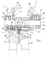
- a ring pusher device has a body 1 in which a slide 2.
- the body 1 comprises, at the rear and lower, a handle 10, and at the front and upper a part 11 having an opening 12 in which is tightly engaged the slider 2, the opening 12 and the part of the slider 2 which is engaged therein being of section round.
- Part 11 is surmounted by a jaw 3 having a semi-cylindrical recess.
- jaw 3 to part 11 is made by sliding in the transverse direction, the base 31 of jaw 3 and part 11 being of profiles complementary, they include grooves 32 and 13 respectively.
- a jaw 4 having a recess semi-cylindrical 40 and a base 41, is assembled to the part rear 20 of the slide 2, the connection being identical, through transverse grooves 42 and 21 respectively.
- Jaws 3 and 4 are intended, depending on the profile recesses 30 and 40, to be adapted either on a fitting, either on a ring, not shown, they can be interconnected either to the slide 2 or to body 1, the choice being a function of the ease of access to the connection.
- the slide 2 has a rack on the underside 24, in the notches 25 from which the lug 50 can mesh a finger 5 articulated on a pivot 51, at the end of a sleeve 52, itself articulated on the body 1 around a pivot 16 adjoining pivot 51.
- the finger 5 internally has a cavity 53 housing a coil spring 17 secured to the body 1 by one of its ends, and disposed under the slide 2, parallel to this one.
- the cavity 53 is flared, and its axis passes between the lug 50 and the pivot 51, so that the coil spring 17, due to its relative freedom of movement in the cavity 53 and its eccentricity with respect to the pivot 51, tends to rotate finger 5 on pivot 51 and put in relation to the lug 50 and the notches 25 of the rack 24.
- the latch 6 has a boss 61 which bears against the pivoting end 54 of finger 5, but so off-center so as to prevent the finger from moving therefore of the handle 52, and on the other hand to maintain the lug 50 disengaged from the rack 24.
- the latch 6 allows the disengaging of finger 5, which allows easy disengagement of the pliers after use.
- the boss 61 has a peripheral edge 62 convex, while the edge 55 the end 54 is concave complementary shape, which allows centering.
- the latch 6 comprises at the base of the boss 60 a convex edge 63 against which the edge 55 of finger 5 when it is in the position further back, that is to say when the handle 52 is in open position as much as possible, which allows disengaging the finger 5.
- handle 52 in open position or closed, allows quick reconciliation of jaws 3 and 4 on the connection and also quick release of the clamp end of work.
- the part 11 has a groove 110 having two parts 111 and 112 parallel to the axis of displacement of the slide 2 and a curved part transverse 113, while the base 31 of the jaw 3 comprises a groove 33 having two parts 34 and 35 parallel to the axis of movement of the slide 2 and a curved part transverse 36.
- the part 20 has a groove 26 having two parts 27 and 28 parallel to the axis of displacement of the slide 2 and a curved part transverse 29, while the base 41 of the jaw 4 has a groove 43 having two parts 44 and 45 parallel to the axis of movement of the slide 2 and a curved part transverse 46.
- the blocking of jaws 3 and 4 can also be produced by means of indexing of the ball and spring type, shown only for jaw 3.
Landscapes
- Engineering & Computer Science (AREA)
- General Engineering & Computer Science (AREA)
- Mechanical Engineering (AREA)
- Gripping Jigs, Holding Jigs, And Positioning Jigs (AREA)
- Clamps And Clips (AREA)
- Hand Tools For Fitting Together And Separating, Or Other Hand Tools (AREA)
- Handcart (AREA)
- Metal Extraction Processes (AREA)
- Surgical Instruments (AREA)
Applications Claiming Priority (2)
| Application Number | Priority Date | Filing Date | Title |
|---|---|---|---|
| FR9711104 | 1997-09-03 | ||
| FR9711104A FR2767736B1 (fr) | 1997-09-03 | 1997-09-03 | Dispositif de pince pousse-bague utilise dans le domaine de la plomberie pour l'emboitement des tuyaux en matiere plastique ou en complexe plastique-aluminium sur des raccords |
Publications (2)
| Publication Number | Publication Date |
|---|---|
| EP0900633A1 true EP0900633A1 (de) | 1999-03-10 |
| EP0900633B1 EP0900633B1 (de) | 2002-08-28 |
Family
ID=9510832
Family Applications (1)
| Application Number | Title | Priority Date | Filing Date |
|---|---|---|---|
| EP98440140A Expired - Lifetime EP0900633B1 (de) | 1997-09-03 | 1998-06-26 | Zange zum Aufschieben von Ringen |
Country Status (6)
| Country | Link |
|---|---|
| EP (1) | EP0900633B1 (de) |
| AT (1) | ATE222841T1 (de) |
| DE (1) | DE69807404T2 (de) |
| ES (1) | ES2183309T3 (de) |
| FR (1) | FR2767736B1 (de) |
| PT (1) | PT900633E (de) |
Cited By (5)
| Publication number | Priority date | Publication date | Assignee | Title |
|---|---|---|---|---|
| EP1231027A3 (de) * | 2001-02-12 | 2005-08-03 | Rothenberger Werkzeuge Aktiengesellschaft | Pressenkopf für das Verbinden von Rohrleitungen |
| WO2005090007A1 (de) * | 2004-03-17 | 2005-09-29 | Holp Gmbh | Werkzeug zum schliessen und trennen von steckbaren schnellverschlusskupplungen |
| FR2868719A1 (fr) * | 2004-04-08 | 2005-10-14 | Foell Remswerk | Dispositif pour appliquer une force de pressage axiale |
| ITMI20091403A1 (it) * | 2009-08-03 | 2011-02-04 | Ritmo Spa | Pressa manuale, particolarmente per giunzioni. |
| EP3078457A1 (de) * | 2015-04-09 | 2016-10-12 | Yung Chi Industry Co., Ltd. | Rohrpressvorrichtung |
Families Citing this family (3)
| Publication number | Priority date | Publication date | Assignee | Title |
|---|---|---|---|---|
| DE102009000153B3 (de) | 2009-01-12 | 2010-07-15 | Rennsteig Werkzeuge Gmbh | Zange zur Herstellung einer Schiebehülsenverbindung |
| CN102922439A (zh) * | 2012-10-26 | 2013-02-13 | 昆山特力伯传动科技有限公司 | 输送带的接口对接钳 |
| DE102017127707A1 (de) | 2017-11-23 | 2019-05-23 | Viega Technology Gmbh & Co. Kg | Wechselbacke für Presswerkzeug |
Citations (6)
| Publication number | Priority date | Publication date | Assignee | Title |
|---|---|---|---|---|
| US2719695A (en) * | 1953-08-17 | 1955-10-04 | John L Mckee | Pulling and pushing apparatus for coupling and uncoupling pipe sections |
| EP0341180A1 (de) * | 1988-05-06 | 1989-11-08 | Andres Santiago S.A. | Vorrichtung zum Verbinden von Gehäusen durch Axialkraft |
| EP0424247A1 (de) * | 1989-10-18 | 1991-04-24 | Mecanique Energetique | Vorrichtung zum Komprimieren von Federn |
| DE9307957U1 (de) * | 1993-05-26 | 1993-07-29 | Vulkan Lokring GmbH & Co. KG, 4690 Herne | Montagewerkzeug für Schiebehülsen-Rohrverbindungen |
| DE4419862C1 (de) * | 1994-06-07 | 1995-11-09 | Rothenberger Werkzeuge Masch | Zangenförmiges Werkzeug |
| WO1996020807A1 (en) * | 1995-01-06 | 1996-07-11 | The Deutsch Company | Axial swage tool having a stabilizing pin |
-
1997
- 1997-09-03 FR FR9711104A patent/FR2767736B1/fr not_active Expired - Fee Related
-
1998
- 1998-06-26 AT AT98440140T patent/ATE222841T1/de not_active IP Right Cessation
- 1998-06-26 EP EP98440140A patent/EP0900633B1/de not_active Expired - Lifetime
- 1998-06-26 PT PT98440140T patent/PT900633E/pt unknown
- 1998-06-26 DE DE69807404T patent/DE69807404T2/de not_active Expired - Lifetime
- 1998-06-26 ES ES98440140T patent/ES2183309T3/es not_active Expired - Lifetime
Patent Citations (6)
| Publication number | Priority date | Publication date | Assignee | Title |
|---|---|---|---|---|
| US2719695A (en) * | 1953-08-17 | 1955-10-04 | John L Mckee | Pulling and pushing apparatus for coupling and uncoupling pipe sections |
| EP0341180A1 (de) * | 1988-05-06 | 1989-11-08 | Andres Santiago S.A. | Vorrichtung zum Verbinden von Gehäusen durch Axialkraft |
| EP0424247A1 (de) * | 1989-10-18 | 1991-04-24 | Mecanique Energetique | Vorrichtung zum Komprimieren von Federn |
| DE9307957U1 (de) * | 1993-05-26 | 1993-07-29 | Vulkan Lokring GmbH & Co. KG, 4690 Herne | Montagewerkzeug für Schiebehülsen-Rohrverbindungen |
| DE4419862C1 (de) * | 1994-06-07 | 1995-11-09 | Rothenberger Werkzeuge Masch | Zangenförmiges Werkzeug |
| WO1996020807A1 (en) * | 1995-01-06 | 1996-07-11 | The Deutsch Company | Axial swage tool having a stabilizing pin |
Cited By (6)
| Publication number | Priority date | Publication date | Assignee | Title |
|---|---|---|---|---|
| EP1231027A3 (de) * | 2001-02-12 | 2005-08-03 | Rothenberger Werkzeuge Aktiengesellschaft | Pressenkopf für das Verbinden von Rohrleitungen |
| WO2005090007A1 (de) * | 2004-03-17 | 2005-09-29 | Holp Gmbh | Werkzeug zum schliessen und trennen von steckbaren schnellverschlusskupplungen |
| FR2868719A1 (fr) * | 2004-04-08 | 2005-10-14 | Foell Remswerk | Dispositif pour appliquer une force de pressage axiale |
| ITMI20091403A1 (it) * | 2009-08-03 | 2011-02-04 | Ritmo Spa | Pressa manuale, particolarmente per giunzioni. |
| EP2281661A1 (de) * | 2009-08-03 | 2011-02-09 | RITMO S.p.A. | Handbetriebene Presse für Verbindungsstellen |
| EP3078457A1 (de) * | 2015-04-09 | 2016-10-12 | Yung Chi Industry Co., Ltd. | Rohrpressvorrichtung |
Also Published As
| Publication number | Publication date |
|---|---|
| PT900633E (pt) | 2002-12-31 |
| DE69807404D1 (de) | 2002-10-02 |
| FR2767736B1 (fr) | 1999-12-03 |
| ES2183309T3 (es) | 2003-03-16 |
| FR2767736A1 (fr) | 1999-03-05 |
| EP0900633B1 (de) | 2002-08-28 |
| DE69807404T2 (de) | 2003-04-17 |
| ATE222841T1 (de) | 2002-09-15 |
Similar Documents
| Publication | Publication Date | Title |
|---|---|---|
| EP0769263B1 (de) | Abnehmbare Vorrichtung zum Greifen eines Geschirrs | |
| EP0023189B1 (de) | Schnellkupplungsvorrichtungen zum Verbinden von Rohrleitungen | |
| FR2883938A1 (fr) | Mousqueton a verrouillage automatique | |
| FR2674309A1 (fr) | Raccord a griffes perfectionne. | |
| EP1026349A1 (de) | Griff für einen Kraftfahrzeugflügel | |
| WO2008122716A1 (fr) | Dispositif de serrage a bras de manouvre escamotable et appareil comportant un tel dispositif | |
| CA2841680C (fr) | Dispositif de prehension amovible d'un recipient culinaire muni de moyens antiretour de deux bras | |
| EP0900633B1 (de) | Zange zum Aufschieben von Ringen | |
| FR3012188A1 (fr) | Fixation a deverrouillage rapide | |
| EP0958896A1 (de) | Mehrzwecktaschenwerkzeug mit einer Zange | |
| EP2811214A1 (de) | Schnelleinrastverbindung mit Riegeln mit symmetrischen Klemmbacken | |
| FR2848890A3 (fr) | Ensemble constitue par une prise et un mecanisme d'encliquetage | |
| WO2010149883A1 (fr) | Canne télescopique notamment destinée à des personnes handicapées | |
| FR2516035A1 (fr) | Dispositif de fixation d'un balai d'essuie-glace sur son bras | |
| CA2591973A1 (fr) | Cle a cliquet | |
| EP1184578A2 (de) | Spannschelle zur schnellen Montage und Demontage | |
| FR2638792A1 (fr) | Dispositif de maintien a poste fixe d'un receptacle | |
| FR2733609A1 (fr) | Mecanisme de retenue de levier de commande | |
| FR2893153A1 (fr) | Dispositif de fixation d'un bracelet de montre | |
| EP0953778A1 (de) | Schnellmontagemutter bestehend aus zwei Mutterhälften, und Befestigungsvorrichtung insbesondere für Betonschalung mit Verwendung dieser Mutter | |
| FR2977821A1 (fr) | Pince serre-joint | |
| FR2774609A1 (fr) | Dispositif de support pour mise en peinture d'elements de carrosserie automobile | |
| EP0812660A1 (de) | Schraubstock | |
| FR2549197A1 (fr) | Raccord pour tuyaux equipe d'un collier de serrage verrouillable | |
| FR3057049A1 (fr) | Raccord hydraulique auto-obturant. |
Legal Events
| Date | Code | Title | Description |
|---|---|---|---|
| PUAI | Public reference made under article 153(3) epc to a published international application that has entered the european phase |
Free format text: ORIGINAL CODE: 0009012 |
|
| AK | Designated contracting states |
Kind code of ref document: A1 Designated state(s): AT BE CH DE DK ES FI FR GB GR IE IT LI LU MC NL PT SE |
|
| AX | Request for extension of the european patent |
Free format text: AL;LT;LV;MK;RO;SI |
|
| 17P | Request for examination filed |
Effective date: 19990907 |
|
| AKX | Designation fees paid |
Free format text: AT BE CH DE DK ES FI FR GB GR IE IT LI LU MC NL PT SE |
|
| 17Q | First examination report despatched |
Effective date: 20010122 |
|
| GRAG | Despatch of communication of intention to grant |
Free format text: ORIGINAL CODE: EPIDOS AGRA |
|
| GRAG | Despatch of communication of intention to grant |
Free format text: ORIGINAL CODE: EPIDOS AGRA |
|
| GRAH | Despatch of communication of intention to grant a patent |
Free format text: ORIGINAL CODE: EPIDOS IGRA |
|
| GRAH | Despatch of communication of intention to grant a patent |
Free format text: ORIGINAL CODE: EPIDOS IGRA |
|
| GRAA | (expected) grant |
Free format text: ORIGINAL CODE: 0009210 |
|
| AK | Designated contracting states |
Kind code of ref document: B1 Designated state(s): AT BE CH DE DK ES FI FR GB GR IE IT LI LU MC NL PT SE |
|
| PG25 | Lapsed in a contracting state [announced via postgrant information from national office to epo] |
Ref country code: IE Free format text: LAPSE BECAUSE OF FAILURE TO SUBMIT A TRANSLATION OF THE DESCRIPTION OR TO PAY THE FEE WITHIN THE PRESCRIBED TIME-LIMIT Effective date: 20020828 Ref country code: FI Free format text: LAPSE BECAUSE OF FAILURE TO SUBMIT A TRANSLATION OF THE DESCRIPTION OR TO PAY THE FEE WITHIN THE PRESCRIBED TIME-LIMIT Effective date: 20020828 |
|
| REF | Corresponds to: |
Ref document number: 222841 Country of ref document: AT Date of ref document: 20020915 Kind code of ref document: T |
|
| REG | Reference to a national code |
Ref country code: GB Ref legal event code: FG4D Free format text: NOT ENGLISH |
|
| REG | Reference to a national code |
Ref country code: CH Ref legal event code: EP |
|
| REF | Corresponds to: |
Ref document number: 69807404 Country of ref document: DE Date of ref document: 20021002 |
|
| REG | Reference to a national code |
Ref country code: IE Ref legal event code: FG4D Free format text: FRENCH |
|
| PG25 | Lapsed in a contracting state [announced via postgrant information from national office to epo] |
Ref country code: DK Free format text: LAPSE BECAUSE OF FAILURE TO SUBMIT A TRANSLATION OF THE DESCRIPTION OR TO PAY THE FEE WITHIN THE PRESCRIBED TIME-LIMIT Effective date: 20021128 |
|
| GBT | Gb: translation of ep patent filed (gb section 77(6)(a)/1977) |
Effective date: 20021119 |
|
| REG | Reference to a national code |
Ref country code: GR Ref legal event code: EP Ref document number: 20020403913 Country of ref document: GR |
|
| REG | Reference to a national code |
Ref country code: PT Ref legal event code: SC4A Free format text: AVAILABILITY OF NATIONAL TRANSLATION Effective date: 20021111 |
|
| REG | Reference to a national code |
Ref country code: ES Ref legal event code: FG2A Ref document number: 2183309 Country of ref document: ES Kind code of ref document: T3 |
|
| REG | Reference to a national code |
Ref country code: IE Ref legal event code: FD4D Ref document number: 0900633E Country of ref document: IE |
|
| PG25 | Lapsed in a contracting state [announced via postgrant information from national office to epo] |
Ref country code: LU Free format text: LAPSE BECAUSE OF NON-PAYMENT OF DUE FEES Effective date: 20030626 Ref country code: AT Free format text: LAPSE BECAUSE OF NON-PAYMENT OF DUE FEES Effective date: 20030626 |
|
| PG25 | Lapsed in a contracting state [announced via postgrant information from national office to epo] |
Ref country code: MC Free format text: LAPSE BECAUSE OF NON-PAYMENT OF DUE FEES Effective date: 20030630 Ref country code: LI Free format text: LAPSE BECAUSE OF NON-PAYMENT OF DUE FEES Effective date: 20030630 Ref country code: CH Free format text: LAPSE BECAUSE OF NON-PAYMENT OF DUE FEES Effective date: 20030630 Ref country code: BE Free format text: LAPSE BECAUSE OF NON-PAYMENT OF DUE FEES Effective date: 20030630 |
|
| PLBE | No opposition filed within time limit |
Free format text: ORIGINAL CODE: 0009261 |
|
| STAA | Information on the status of an ep patent application or granted ep patent |
Free format text: STATUS: NO OPPOSITION FILED WITHIN TIME LIMIT |
|
| 26N | No opposition filed |
Effective date: 20030530 |
|
| BERE | Be: lapsed |
Owner name: S.A. *VIRAX Effective date: 20030630 |
|
| PG25 | Lapsed in a contracting state [announced via postgrant information from national office to epo] |
Ref country code: PT Free format text: LAPSE BECAUSE OF NON-PAYMENT OF DUE FEES Effective date: 20031231 |
|
| PG25 | Lapsed in a contracting state [announced via postgrant information from national office to epo] |
Ref country code: GR Free format text: LAPSE BECAUSE OF NON-PAYMENT OF DUE FEES Effective date: 20040107 |
|
| REG | Reference to a national code |
Ref country code: CH Ref legal event code: PL |
|
| REG | Reference to a national code |
Ref country code: PT Ref legal event code: MM4A Free format text: LAPSE DUE TO NON-PAYMENT OF FEES Effective date: 20031231 |
|
| PGFP | Annual fee paid to national office [announced via postgrant information from national office to epo] |
Ref country code: ES Payment date: 20120627 Year of fee payment: 15 |
|
| PGFP | Annual fee paid to national office [announced via postgrant information from national office to epo] |
Ref country code: SE Payment date: 20130619 Year of fee payment: 16 Ref country code: DE Payment date: 20130620 Year of fee payment: 16 Ref country code: GB Payment date: 20130619 Year of fee payment: 16 |
|
| PGFP | Annual fee paid to national office [announced via postgrant information from national office to epo] |
Ref country code: NL Payment date: 20130619 Year of fee payment: 16 Ref country code: IT Payment date: 20130625 Year of fee payment: 16 |
|
| PGFP | Annual fee paid to national office [announced via postgrant information from national office to epo] |
Ref country code: FR Payment date: 20130712 Year of fee payment: 16 |
|
| REG | Reference to a national code |
Ref country code: DE Ref legal event code: R119 Ref document number: 69807404 Country of ref document: DE |
|
| REG | Reference to a national code |
Ref country code: NL Ref legal event code: V1 Effective date: 20150101 |
|
| PG25 | Lapsed in a contracting state [announced via postgrant information from national office to epo] |
Ref country code: SE Free format text: LAPSE BECAUSE OF NON-PAYMENT OF DUE FEES Effective date: 20140627 |
|
| REG | Reference to a national code |
Ref country code: SE Ref legal event code: EUG |
|
| GBPC | Gb: european patent ceased through non-payment of renewal fee |
Effective date: 20140626 |
|
| REG | Reference to a national code |
Ref country code: FR Ref legal event code: ST Effective date: 20150227 |
|
| PG25 | Lapsed in a contracting state [announced via postgrant information from national office to epo] |
Ref country code: NL Free format text: LAPSE BECAUSE OF NON-PAYMENT OF DUE FEES Effective date: 20150101 |
|
| REG | Reference to a national code |
Ref country code: DE Ref legal event code: R119 Ref document number: 69807404 Country of ref document: DE Effective date: 20150101 |
|
| PG25 | Lapsed in a contracting state [announced via postgrant information from national office to epo] |
Ref country code: IT Free format text: LAPSE BECAUSE OF NON-PAYMENT OF DUE FEES Effective date: 20140626 Ref country code: DE Free format text: LAPSE BECAUSE OF NON-PAYMENT OF DUE FEES Effective date: 20150101 |
|
| PG25 | Lapsed in a contracting state [announced via postgrant information from national office to epo] |
Ref country code: FR Free format text: LAPSE BECAUSE OF NON-PAYMENT OF DUE FEES Effective date: 20140630 Ref country code: GB Free format text: LAPSE BECAUSE OF NON-PAYMENT OF DUE FEES Effective date: 20140626 |
|
| REG | Reference to a national code |
Ref country code: ES Ref legal event code: FD2A Effective date: 20150727 |
|
| PG25 | Lapsed in a contracting state [announced via postgrant information from national office to epo] |
Ref country code: ES Free format text: LAPSE BECAUSE OF NON-PAYMENT OF DUE FEES Effective date: 20140627 |