EP0900677B1 - Lagerung eines Stabilisators an einem Kraftfahrzeug - Google Patents
Lagerung eines Stabilisators an einem Kraftfahrzeug Download PDFInfo
- Publication number
- EP0900677B1 EP0900677B1 EP98116609A EP98116609A EP0900677B1 EP 0900677 B1 EP0900677 B1 EP 0900677B1 EP 98116609 A EP98116609 A EP 98116609A EP 98116609 A EP98116609 A EP 98116609A EP 0900677 B1 EP0900677 B1 EP 0900677B1
- Authority
- EP
- European Patent Office
- Prior art keywords
- bearing
- stabiliser
- stabilizer
- sliding
- counter
- Prior art date
- Legal status (The legal status is an assumption and is not a legal conclusion. Google has not performed a legal analysis and makes no representation as to the accuracy of the status listed.)
- Expired - Lifetime
Links
- 239000003381 stabilizer Substances 0.000 title claims description 41
- 239000004033 plastic Substances 0.000 claims description 12
- 229920003023 plastic Polymers 0.000 claims description 12
- 239000000463 material Substances 0.000 claims description 5
- 235000015095 lager Nutrition 0.000 description 5
- 238000007789 sealing Methods 0.000 description 5
- 238000003860 storage Methods 0.000 description 5
- 229920001971 elastomer Polymers 0.000 description 3
- 238000004519 manufacturing process Methods 0.000 description 3
- 229910000831 Steel Inorganic materials 0.000 description 2
- 230000005540 biological transmission Effects 0.000 description 2
- 239000000806 elastomer Substances 0.000 description 2
- 229920001343 polytetrafluoroethylene Polymers 0.000 description 2
- 239000004810 polytetrafluoroethylene Substances 0.000 description 2
- 239000010959 steel Substances 0.000 description 2
- 229920000049 Carbon (fiber) Polymers 0.000 description 1
- 229920002430 Fibre-reinforced plastic Polymers 0.000 description 1
- ZOKXTWBITQBERF-UHFFFAOYSA-N Molybdenum Chemical compound [Mo] ZOKXTWBITQBERF-UHFFFAOYSA-N 0.000 description 1
- 239000004952 Polyamide Substances 0.000 description 1
- 238000004026 adhesive bonding Methods 0.000 description 1
- 230000015572 biosynthetic process Effects 0.000 description 1
- 239000004917 carbon fiber Substances 0.000 description 1
- 230000005489 elastic deformation Effects 0.000 description 1
- HQQADJVZYDDRJT-UHFFFAOYSA-N ethene;prop-1-ene Chemical group C=C.CC=C HQQADJVZYDDRJT-UHFFFAOYSA-N 0.000 description 1
- 239000000835 fiber Substances 0.000 description 1
- 239000011151 fibre-reinforced plastic Substances 0.000 description 1
- 239000004519 grease Substances 0.000 description 1
- 238000007373 indentation Methods 0.000 description 1
- 239000000314 lubricant Substances 0.000 description 1
- 238000000034 method Methods 0.000 description 1
- 229910052750 molybdenum Inorganic materials 0.000 description 1
- 239000011733 molybdenum Substances 0.000 description 1
- 229920002647 polyamide Polymers 0.000 description 1
- 229920001296 polysiloxane Polymers 0.000 description 1
- -1 polytetrafluoroethylene Polymers 0.000 description 1
- 239000005060 rubber Substances 0.000 description 1
- 238000005507 spraying Methods 0.000 description 1
- 239000000126 substance Substances 0.000 description 1
- 239000000725 suspension Substances 0.000 description 1
- 229920001897 terpolymer Polymers 0.000 description 1
- 230000007704 transition Effects 0.000 description 1
Images

Classifications
-
- B—PERFORMING OPERATIONS; TRANSPORTING
- B60—VEHICLES IN GENERAL
- B60G—VEHICLE SUSPENSION ARRANGEMENTS
- B60G7/00—Pivoted suspension arms; Accessories thereof
- B60G7/005—Ball joints
-
- B—PERFORMING OPERATIONS; TRANSPORTING
- B60—VEHICLES IN GENERAL
- B60G—VEHICLE SUSPENSION ARRANGEMENTS
- B60G21/00—Interconnection systems for two or more resiliently-suspended wheels, e.g. for stabilising a vehicle body with respect to acceleration, deceleration or centrifugal forces
- B60G21/02—Interconnection systems for two or more resiliently-suspended wheels, e.g. for stabilising a vehicle body with respect to acceleration, deceleration or centrifugal forces permanently interconnected
- B60G21/04—Interconnection systems for two or more resiliently-suspended wheels, e.g. for stabilising a vehicle body with respect to acceleration, deceleration or centrifugal forces permanently interconnected mechanically
- B60G21/05—Interconnection systems for two or more resiliently-suspended wheels, e.g. for stabilising a vehicle body with respect to acceleration, deceleration or centrifugal forces permanently interconnected mechanically between wheels on the same axle but on different sides of the vehicle, i.e. the left and right wheel suspensions being interconnected
- B60G21/055—Stabiliser bars
- B60G21/0551—Mounting means therefor
-
- F—MECHANICAL ENGINEERING; LIGHTING; HEATING; WEAPONS; BLASTING
- F16—ENGINEERING ELEMENTS AND UNITS; GENERAL MEASURES FOR PRODUCING AND MAINTAINING EFFECTIVE FUNCTIONING OF MACHINES OR INSTALLATIONS; THERMAL INSULATION IN GENERAL
- F16C—SHAFTS; FLEXIBLE SHAFTS; ELEMENTS OR CRANKSHAFT MECHANISMS; ROTARY BODIES OTHER THAN GEARING ELEMENTS; BEARINGS
- F16C11/00—Pivots; Pivotal connections
- F16C11/04—Pivotal connections
- F16C11/06—Ball-joints; Other joints having more than one degree of angular freedom, i.e. universal joints
- F16C11/0614—Ball-joints; Other joints having more than one degree of angular freedom, i.e. universal joints the female part of the joint being open on two sides
-
- B—PERFORMING OPERATIONS; TRANSPORTING
- B60—VEHICLES IN GENERAL
- B60G—VEHICLE SUSPENSION ARRANGEMENTS
- B60G2202/00—Indexing codes relating to the type of spring, damper or actuator
- B60G2202/10—Type of spring
- B60G2202/13—Torsion spring
- B60G2202/135—Stabiliser bar and/or tube
-
- B—PERFORMING OPERATIONS; TRANSPORTING
- B60—VEHICLES IN GENERAL
- B60G—VEHICLE SUSPENSION ARRANGEMENTS
- B60G2204/00—Indexing codes related to suspensions per se or to auxiliary parts
- B60G2204/10—Mounting of suspension elements
- B60G2204/12—Mounting of springs or dampers
- B60G2204/122—Mounting of torsion springs
- B60G2204/1222—Middle mounts of stabiliser on vehicle body or chassis
-
- B—PERFORMING OPERATIONS; TRANSPORTING
- B60—VEHICLES IN GENERAL
- B60G—VEHICLE SUSPENSION ARRANGEMENTS
- B60G2204/00—Indexing codes related to suspensions per se or to auxiliary parts
- B60G2204/40—Auxiliary suspension parts; Adjustment of suspensions
- B60G2204/416—Ball or spherical joints
-
- B—PERFORMING OPERATIONS; TRANSPORTING
- B60—VEHICLES IN GENERAL
- B60G—VEHICLE SUSPENSION ARRANGEMENTS
- B60G2204/00—Indexing codes related to suspensions per se or to auxiliary parts
- B60G2204/40—Auxiliary suspension parts; Adjustment of suspensions
- B60G2204/44—Centering or positioning means
-
- B—PERFORMING OPERATIONS; TRANSPORTING
- B60—VEHICLES IN GENERAL
- B60G—VEHICLE SUSPENSION ARRANGEMENTS
- B60G2204/00—Indexing codes related to suspensions per se or to auxiliary parts
- B60G2204/40—Auxiliary suspension parts; Adjustment of suspensions
- B60G2204/45—Stops limiting travel
-
- B—PERFORMING OPERATIONS; TRANSPORTING
- B60—VEHICLES IN GENERAL
- B60G—VEHICLE SUSPENSION ARRANGEMENTS
- B60G2206/00—Indexing codes related to the manufacturing of suspensions: constructional features, the materials used, procedures or tools
- B60G2206/01—Constructional features of suspension elements, e.g. arms, dampers, springs
- B60G2206/40—Constructional features of dampers and/or springs
- B60G2206/42—Springs
- B60G2206/427—Stabiliser bars or tubes
-
- B—PERFORMING OPERATIONS; TRANSPORTING
- B60—VEHICLES IN GENERAL
- B60G—VEHICLE SUSPENSION ARRANGEMENTS
- B60G2206/00—Indexing codes related to the manufacturing of suspensions: constructional features, the materials used, procedures or tools
- B60G2206/01—Constructional features of suspension elements, e.g. arms, dampers, springs
- B60G2206/80—Manufacturing procedures
- B60G2206/82—Joining
- B60G2206/8209—Joining by deformation
-
- B—PERFORMING OPERATIONS; TRANSPORTING
- B60—VEHICLES IN GENERAL
- B60G—VEHICLE SUSPENSION ARRANGEMENTS
- B60G2206/00—Indexing codes related to the manufacturing of suspensions: constructional features, the materials used, procedures or tools
- B60G2206/01—Constructional features of suspension elements, e.g. arms, dampers, springs
- B60G2206/90—Maintenance
- B60G2206/91—Assembly procedures
-
- F—MECHANICAL ENGINEERING; LIGHTING; HEATING; WEAPONS; BLASTING
- F16—ENGINEERING ELEMENTS AND UNITS; GENERAL MEASURES FOR PRODUCING AND MAINTAINING EFFECTIVE FUNCTIONING OF MACHINES OR INSTALLATIONS; THERMAL INSULATION IN GENERAL
- F16C—SHAFTS; FLEXIBLE SHAFTS; ELEMENTS OR CRANKSHAFT MECHANISMS; ROTARY BODIES OTHER THAN GEARING ELEMENTS; BEARINGS
- F16C2326/00—Articles relating to transporting
- F16C2326/01—Parts of vehicles in general
- F16C2326/05—Vehicle suspensions, e.g. bearings, pivots or connecting rods used therein
Definitions
- the invention relates to the mounting of a stabilizer on a motor vehicle according to the preamble of claim 1.
- bearing bushes for example for storing stabilizers, to be designed so that they consist of a housing in which can be rotated a plastic sleeve holding a hub.
- Such bushings are in the WO 94/13967.
- the hub and plastic sleeve can be form-fitting engage with each other.
- For fastening the stabilizer in the hub most figures show a hub with a central, frustoconical through hole, suggesting that an interference fit between the stabilizer and Hub is provided.
- the famous camp is due to its special Arrangement on a section extending in the longitudinal direction of the motor vehicle of the stabilizer for the transmission of swiveling movements in one the transverse direction of the motor vehicle extending axis. Because both the bearing housing and the housing surrounding the bearing housing in two parts are constructed, the manufacture and assembly of the known bearing is complex.
- the object of the invention is to mount a stabilizer on a motor vehicle to create, which is simple and despite the seal builds compact. This object is achieved according to the invention by the features of claim 1.
- the sealing surface can vary depending on the intended use extend substantially radially or axially. It is also an advantage that in addition to the portability of Axial forces a limited swivel movement perpendicular to the longitudinal axis of the Stabilizer and also a rotary movement around the longitudinal axis of the stabilizer is possible.
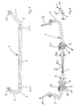
- the Stabilizer 1 shows a stabilizer 1 for a motor vehicle, not shown.
- the Stabilizer 1 has an approximately rectilinear central section 2 and two adjoining end sections running at an angle 3 and 4, the angle usually being between 70 and 110 °.
- two slide bearing parts 13, 14 of two bearings 5, 6 at the designated storage locations near the respective transition 7, 8 formed from the middle section 2 to the corresponding end section 3, 4.
- the respective slide bearing part 13, 14 consists of a slide-optimized plastic, the directly on the stabilizer 1, preferably by a spraying process in which 1 is applied.
- FIG. 2 shows the respective outer housing 15, 16 of the respective bearing point 5, 6, which is arranged in each case via a clamp-shaped fastening part 17, 18 on a flange 19, 20 or the like of an axle (not shown) or a part thereof.
- the degrees of freedom ⁇ and ⁇ of the stabilizer 1 are shown in the form of arrows in FIG. 2.
- the bearings 5, 6 with the respective spherical or crowned slide bearing part 13, 14, a rotational movement ⁇ about the y-axis is possible.
- the bearings 5, 6 allow a limited pivoting movement about an angle ⁇ about the x-axis.
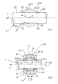
- FIG. 3 shows an enlarged illustration of a slide bearing part shown in FIG. 1 13, 14 in longitudinal section.
- the slide bearing part 13, 14 has a through opening 21 on.
- the slide bearing part 13, 14 shown in FIGS. 1 and 3 has a central, spherical section 24 for transmitting the occurring bearing forces. On this spherical section is closed by a circumferential channel-shaped section Recess 25, 26 and to the respective depression 25, 26 in one piece an annular Section 27, 28.
- the one pointing away from the central section 24 is used respective end surface 29, 30 of the corresponding section 27, 28 as a sealing surface, to prevent dirt, moisture or the like from entering.
- the 1, 3, 4, 6, 7 and 8 embodiments have as a common Characteristic on that the center M of a sphere with a radius r represents Range of the respective slide bearing part on the longitudinal axis or y-axis the middle section 2 of the stabilizer 1.
- the focus is accordingly an inner surface of each, the spherical portion at least partially surrounding counter bearing part in the same place.
- the counter bearing parts 32, 33 usually consist of a non-slip modified material, for example made of plastic, steel or plastic shells in which steel is stored is.
- the plastic is preferably polyamide PA and / or PPE and / or PBT used.
- the slide bearing part 13, 14 is preferably a slide-optimized material, for example a fiber-reinforced plastic, the fibers used are preferably carbon fibers.
- lubricious substances such as silicone, polytetrafluoroethylene Materials containing PTFE and / or molybdenum may be incorporated.
- dry storage can also be used with conventional lubricants such as z. B. grease.
- the counter bearing parts 32, 33 are in a bearing housing 35 embedded and fastened, the bearing housing 35 one in FIG. 5th recognizable mounting slot 42.
- the bearing housing 35 is preferably made from an ethylene-propylene terpolymer rubber or from one other elastomer.
- the bearing housing 35 lies with an annular section 36, 37 of its respective side wall 38, 39 on the corresponding end face 29, 30 of the respective annular portion 27, 28 of the slide bearing part 13, 14 for Formation of a sealing surface.
- On the outer surface 40 of the bearing housing 35 is a fastening part 41, the shape and course of which is shown in FIG. 6 evident.
- the bearing housing 35 and the fastening part 41 are U-shaped Have cross-section, the fastening part 41 additionally with lateral, horizontal sections 44, 45 is provided.
- the fastener 41 corresponds to the fastening parts 17, 18 shown in FIG. 2.
- the sections 44, 45 of the fastening part 41 are provided with through openings 46, 47 for a fastening element, not shown, for example a screw.
- the counter bearing part consists in the embodiment shown in FIG. 6 from two hemispherical shells 48, 49, which are fastened in the bearing housing 35 are.
- the two shells 48, 49 are usually on their opposite Margins a few millimeters apart.
- the slot 42 is formed in the bearing housing 35.
- the fastening part 41 or 17, 18 is on a flange-shaped fastening part 19, 20 arranged, which is usually an axle component of a motor vehicle heard.
- FIG. 7 shows a second embodiment of a mounting of a stabilizer 1 shown, in which a slide bearing part 51 instead of groove-shaped depressions 25, 26 as in 1, 3 and 4 cylindrical, lateral sections 52, 53 having.
- the surfaces 54, 55 of the sections 52, 53 serve as a sealing surface in Connection with an opposite outer surface 56, 57 each Bearing housing 58.
- the bearing 59 of FIG. 7 also has the same mobility like the bearings 5, 6 of FIGS. 1 to 6.
- Fig. 8 shows a bearing 60, in which, in contrast to the previous counter bearing parts the two counter bearing parts 61, 62 next to the middle, spherical Section 63 additionally the two lateral sections 64, 65 of the slide bearing part 66 covered. This will make the sliding swivel movement around the x-axis substantially prevented by the angle ⁇ . Due to the elastomer content in the Slide bearing part 66 and possibly in the counter bearing parts 61, 62 is nevertheless by a elastic deformation of the bearing 60 a pivoting movement ⁇ about the x-axis possible.
Landscapes
- Engineering & Computer Science (AREA)
- Mechanical Engineering (AREA)
- General Engineering & Computer Science (AREA)
- Vehicle Body Suspensions (AREA)
- Support Of The Bearing (AREA)
- Sliding-Contact Bearings (AREA)
Description
- Fig. 1
- eine perspektivische Darstellung eines Stabilisators, an dessen sich in Kraftfahrzeug-Querrichtung erstreckenden Abschnitt beabstandet voneinander jeweils ein Gleitlagerteil an der dafür vorgesehenen Lagerstelle teilweise ausgebildet ist,
- Fig. 2
- eine perspektivische Darstellung des in der Fig. 1 gezeigten Stabilisators mit vollständig ausgebildeten Lagern,
- Fig. 3
- einen Längsschnitt durch eine in der Fig. 1 gezeigte erste Ausführungsform eines auf dem Stabilisator ausgebildeten Gleitlagerteils,
- Fig. 4
- einen Längsschnitt durch ein in der Fig. 2 dargestelltes Lager,
- Fig. 5
- eine perspektivische Ansicht eines Gehäuses eines in der Fig. 2 dargestellten Lagers,
- Fig. 6
- einen Querschnitt durch ein in der Fig. 2 dargestelltes Lager,
- Fig. 7
- einen Längsschnitt einer zweiten Ausführungsform eines auf einem Stabilisator angeordneten Lagers und
- Fig. 8
- einen Längsschnitt einer dritten Ausführungsform eines auf einem Stabilisator angeordneten Lagers.
Claims (6)
- Lagerung eines Stabilisators (1) an einem Kraftfahrzeug, mit einem inneren, an der Oberfläche des Stabilisators (1) angeordneten Gleitlagerteil (13, 14, 51, 66) mit balliger oder kugelförmiger Gleitlagerfläche (34), das direkt auf den Stabilisator (1) aufgebracht ist und mit mindestens zwei an dem Gleitlagerteil (13, 14, 51, 66) anliegenden Gegenlagerteilen (32, 33, 48, 49, 61, 62), die in einem Lagergehäuse (35) angeordnet sind, dadurch gekennzeichnet, dass das Gleitlagerteil (13, 14, 51, 66) aus einem gleitoptimierten Kunststoff besteht und seitliche Abschnitte (27, 28, 52, 53, 64, 65) aufweist, die mit gegenüberliegenden Flächen (36, 37, 56, 57) der Durchgangsöffnung (43) des Lagergehäuses (35, 58) Dichtungen bilden.
- Lagerung nach Anspruch 1, dadurch gekennzeichnet, dass der aufgebrachte Kunststoff des Gleitlagerteils (13, 14, 51, 66) formschlüssig mit der Oberfläche (22) des Stabilisators (1) verbunden ist.
- Lagerung nach einem der vorhergehenden Ansprüche, dadurch gekennzeichnet, dass die Gegenlagerteile (32, 33) den kugelförmigen Abschnitt (24) des Gleitlagerteils (13, 14) nur so weit umfassen, dass der Stabilisator (1) in dem Lager (5, 6, 59) um die Querachse x des Stabilisators (1) über einen Winkel β, insbesondere 6° bis 20°, schwenkbar ist.
- Lagerung nach einem der Ansprüche 1 oder 2, dadurch gekennzeichnet, dass die Gegenlagerteile (61, 62) den kugelförmigen Abschnitt (63) des Gleitlagerteils (66) so weit umfassen, dass der Stabilisator (1) in dem Lager (60) in bezug auf die Querachse x gleitend unbeweglich und nur über die elastische Verformbarkeit des Lagers (60) um einen Winkel β schwenkbar ist.
- Lagerung nach einem der vorhergehenden Ansprüche, dadurch gekennzeichnet, dass durch die kugelförmige Ausbildung des Lagers (5, 6, 59, 60) Axialkräfte in Richtung der Längsachse des Stabilisators (1) übertragbar sind und dass der Stabilisator (1) um seine Längsachse y um einen Winkel α verdrehbar ist.
- Lagerung nach einem der vorhergehenden Ansprüche, dadurch gekennzeichnet, dass das Lagergehäuse (35, 58) über ein das Lagergehäuse (35, 58) umgreifendes Befestigungsteil (17, 18, 41) an einem Kraftfahrzeugbauteil (19, 20), insbesondere einem Achsbauteil, angeordnet ist.
Applications Claiming Priority (2)
| Application Number | Priority Date | Filing Date | Title |
|---|---|---|---|
| DE19738769 | 1997-09-04 | ||
| DE19738769A DE19738769A1 (de) | 1997-09-04 | 1997-09-04 | Lagerung eines Stabilisators an einem Kraftfahrzeug |
Publications (2)
| Publication Number | Publication Date |
|---|---|
| EP0900677A1 EP0900677A1 (de) | 1999-03-10 |
| EP0900677B1 true EP0900677B1 (de) | 2003-03-05 |
Family
ID=7841240
Family Applications (1)
| Application Number | Title | Priority Date | Filing Date |
|---|---|---|---|
| EP98116609A Expired - Lifetime EP0900677B1 (de) | 1997-09-04 | 1998-09-02 | Lagerung eines Stabilisators an einem Kraftfahrzeug |
Country Status (3)
| Country | Link |
|---|---|
| EP (1) | EP0900677B1 (de) |
| DE (2) | DE19738769A1 (de) |
| ES (1) | ES2191233T3 (de) |
Families Citing this family (26)
| Publication number | Priority date | Publication date | Assignee | Title |
|---|---|---|---|---|
| DE19912268A1 (de) * | 1999-03-19 | 2000-09-28 | Audi Ag | Lagerung für einen Stabilisator |
| DE10018776C1 (de) * | 2000-04-15 | 2001-07-26 | Porsche Ag | Lagerung für einen Stabilisator einer Radaufhängung für Kraftfahrzeuge |
| DE10135386A1 (de) * | 2001-07-25 | 2003-02-13 | Zf Lemfoerder Metallwaren Ag | Kugelgelenk |
| DE20116656U1 (de) | 2001-10-10 | 2002-01-31 | Cramer Kupplung GmbH & Co. KG, 45356 Essen | Anhängerkupplung, insbesondere für Lastkraftwagen |
| DE10154193A1 (de) * | 2001-11-07 | 2003-05-15 | Zf Lemfoerder Metallwaren Ag | Hülsengelenk |
| SE0400549D0 (sv) * | 2004-03-05 | 2004-03-05 | Kongsberg Automotive Asa | Torsjonsstang |
| US7318593B2 (en) * | 2004-10-15 | 2008-01-15 | Ford Global Technologies, Llc | Stabilizer bar and bushing assembly |
| US20070241526A1 (en) * | 2006-04-13 | 2007-10-18 | Martin Joseph Plante | Vehicle stabilizer bar bushing assembly |
| JP4638457B2 (ja) * | 2007-02-27 | 2011-02-23 | 本田技研工業株式会社 | スタビライザーの支持構造 |
| JP2008239137A (ja) * | 2007-02-27 | 2008-10-09 | Honda Motor Co Ltd | スタビライザーの支持構造 |
| EP2125399B1 (de) * | 2007-02-27 | 2013-04-17 | Honda Motor Co., Ltd. | Stützstruktur für stabilisator |
| JP2009196505A (ja) * | 2008-02-21 | 2009-09-03 | Nhk Spring Co Ltd | 車両用スタビライザ |
| JP4663752B2 (ja) | 2008-04-14 | 2011-04-06 | 日本発條株式会社 | スタビライザ装置およびその製造方法 |
| JP5748318B2 (ja) * | 2008-07-18 | 2015-07-15 | 日本発條株式会社 | スタビライザー装置 |
| JP5398192B2 (ja) | 2008-07-29 | 2014-01-29 | 日本発條株式会社 | スタビライザ装置およびその製造方法 |
| DE102010044798A1 (de) | 2010-09-09 | 2012-03-15 | Benteler Automobiltechnik Gmbh | Verfahren zur Herstellung eines Stabilisators sowie Stabilisator |
| WO2015088459A1 (en) * | 2013-12-12 | 2015-06-18 | Otokar Otomotiv Ve Savunma Sanayi Anonim Sirketi | Stabilizer with rubber bearing |
| JP6257353B2 (ja) * | 2014-01-31 | 2018-01-10 | 住友理工株式会社 | スタビライザブッシュ |
| DE102016223615A1 (de) | 2016-11-29 | 2018-05-30 | Schaeffler Technologies AG & Co. KG | Stabilisatorlager für ein Fahrwerk |
| DE102017109144A1 (de) * | 2017-04-28 | 2018-10-31 | Schaeffler Technologies AG & Co. KG | Lageranordnung für einen Wankstabilisator und Fahrwerk mit dem Wankstabilisator |
| CN109340247A (zh) * | 2018-11-07 | 2019-02-15 | 博戈橡胶塑料(株洲)有限公司 | 一种弹性球铰用突块型复合芯轴 |
| CN109555780A (zh) * | 2018-11-07 | 2019-04-02 | 博戈橡胶塑料(株洲)有限公司 | 一种弹性球铰用突块型芯轴的制作方法 |
| CN109340248A (zh) * | 2018-11-07 | 2019-02-15 | 博戈橡胶塑料(株洲)有限公司 | 一种具有复合突块芯轴的弹性球铰 |
| CN109578429B (zh) * | 2018-11-07 | 2021-09-28 | 博戈橡胶塑料(株洲)有限公司 | 一种可转动复合芯轴的弹性球铰 |
| DE102019113484B4 (de) * | 2019-05-21 | 2024-07-11 | Muhr Und Bender Kg | Schelle zum Lagern eines Stabilisators |
| DE102024135065A1 (de) * | 2024-11-27 | 2026-05-28 | Sumitomo Riko Company Limited | Drehstablager mit radialem Anschlag |
Family Cites Families (8)
| Publication number | Priority date | Publication date | Assignee | Title |
|---|---|---|---|---|
| FR2480683A1 (fr) * | 1980-04-21 | 1981-10-23 | Peugeot | Dispositif de maintien transversal de la barre antidevers dans une suspension de vehicule automobile |
| DE3327817A1 (de) * | 1983-08-02 | 1985-02-14 | Jörn, geb. Roth, Frieda, 7012 Fellbach | Gummi-metall-buchse, insbesondere fuer die lagerung eines stabilisators an einem kraftfahrzeug |
| FR2574886A1 (fr) * | 1984-12-18 | 1986-06-20 | Renault | Palier d'articulation, notamment pour barre antidevers du vehicule automobile |
| DE3903350C1 (de) * | 1989-02-04 | 1990-08-30 | Joern Gmbh, 7012 Fellbach, De | |
| DE3921457A1 (de) * | 1989-06-30 | 1991-01-10 | Hoesch Ag | Torsionsstab |
| TW235990B (de) * | 1992-12-16 | 1994-12-11 | Taylor Gordon Joseph | |
| DE4312958A1 (de) * | 1993-04-21 | 1994-10-27 | Lemfoerder Metallwaren Ag | Kunststofflager für Stabilisatoren in Kraftfahrzeugen |
| GB9521852D0 (en) * | 1995-10-25 | 1996-01-03 | Jaguar Cars | Improvements in and relating to anti-roll bar assemblies for road vehicles |
-
1997
- 1997-09-04 DE DE19738769A patent/DE19738769A1/de not_active Withdrawn
-
1998
- 1998-09-02 DE DE59807364T patent/DE59807364D1/de not_active Expired - Fee Related
- 1998-09-02 EP EP98116609A patent/EP0900677B1/de not_active Expired - Lifetime
- 1998-09-02 ES ES98116609T patent/ES2191233T3/es not_active Expired - Lifetime
Also Published As
| Publication number | Publication date |
|---|---|
| EP0900677A1 (de) | 1999-03-10 |
| DE59807364D1 (de) | 2003-04-10 |
| ES2191233T3 (es) | 2003-09-01 |
| DE19738769A1 (de) | 1999-03-11 |
Similar Documents
| Publication | Publication Date | Title |
|---|---|---|
| EP0900677A1 (de) | Lagerung eines Stabilisators an einem Kraftfahrzeug | |
| DE69203261T2 (de) | Aufbau einer Lagerschale. | |
| EP1047883B1 (de) | Doppelgelenk für lenkwellen in kraftfahrzeugen | |
| DE102012211457B4 (de) | Federbeinlager | |
| DE3023963A1 (de) | Stuetzlager fuer ein kugelgelenk | |
| DE10204975A1 (de) | Drehgelenk | |
| EP0183747B1 (de) | Drehschwingungstilger | |
| WO2000015967A1 (de) | Kugelgelenk | |
| EP0950552B1 (de) | Lagerung eines Stabilisators | |
| EP0226702A1 (de) | Federelement | |
| DE102016216598A1 (de) | Federbeinlager | |
| EP4119368A1 (de) | Gelenklager für die abstützung eines fahrzeug-lenkerarms | |
| DE102007054468A1 (de) | Halterungseinrichtung für den Achsschenkel eines Kraftfahrzeugs | |
| DE102015217416A1 (de) | Federbeinlager | |
| DE102016217300B4 (de) | Federbeinlager | |
| EP0570626B1 (de) | Schwenklager | |
| DE102015217415A1 (de) | Federbeinlager | |
| DE102016215755A1 (de) | Federbeinlagerung mit Gleitlager | |
| DE102016208720B4 (de) | Federbeinlager | |
| EP1225355B1 (de) | Dichtungssystem für ein Lager eines Kreuzgelenkes | |
| DE10362009B4 (de) | Kugelgelenk | |
| DE102021203194B3 (de) | Kugelgelenk und Fahrwerkbauteil für ein Kraftfahrzeug und mit einem solchen Kugelgelenk | |
| DE102017125906B4 (de) | Federbeinlager für ein Federbein | |
| EP1049881B1 (de) | Doppelgelenk für lenkwellen in kraftfahrzeugen | |
| DE19956293B4 (de) | Umlenkbeschlag für einen Sicherheitsgurt |
Legal Events
| Date | Code | Title | Description |
|---|---|---|---|
| PUAI | Public reference made under article 153(3) epc to a published international application that has entered the european phase |
Free format text: ORIGINAL CODE: 0009012 |
|
| AK | Designated contracting states |
Kind code of ref document: A1 Designated state(s): DE ES FR GB IT |
|
| AX | Request for extension of the european patent |
Free format text: AL;LT;LV;MK;RO;SI |
|
| 17P | Request for examination filed |
Effective date: 19990503 |
|
| AKX | Designation fees paid |
Free format text: DE ES FR GB IT |
|
| 17Q | First examination report despatched |
Effective date: 20010831 |
|
| GRAH | Despatch of communication of intention to grant a patent |
Free format text: ORIGINAL CODE: EPIDOS IGRA |
|
| GRAH | Despatch of communication of intention to grant a patent |
Free format text: ORIGINAL CODE: EPIDOS IGRA |
|
| GRAA | (expected) grant |
Free format text: ORIGINAL CODE: 0009210 |
|
| AK | Designated contracting states |
Designated state(s): DE ES FR GB IT |
|
| REG | Reference to a national code |
Ref country code: GB Ref legal event code: FG4D Free format text: NOT ENGLISH |
|
| REF | Corresponds to: |
Ref document number: 59807364 Country of ref document: DE Date of ref document: 20030410 Kind code of ref document: P |
|
| GBT | Gb: translation of ep patent filed (gb section 77(6)(a)/1977) |
Effective date: 20030404 |
|
| ET | Fr: translation filed | ||
| REG | Reference to a national code |
Ref country code: ES Ref legal event code: FG2A Ref document number: 2191233 Country of ref document: ES Kind code of ref document: T3 |
|
| PLBE | No opposition filed within time limit |
Free format text: ORIGINAL CODE: 0009261 |
|
| STAA | Information on the status of an ep patent application or granted ep patent |
Free format text: STATUS: NO OPPOSITION FILED WITHIN TIME LIMIT |
|
| 26N | No opposition filed |
Effective date: 20031208 |
|
| PGFP | Annual fee paid to national office [announced via postgrant information from national office to epo] |
Ref country code: ES Payment date: 20040830 Year of fee payment: 7 |
|
| PGFP | Annual fee paid to national office [announced via postgrant information from national office to epo] |
Ref country code: GB Payment date: 20040902 Year of fee payment: 7 |
|
| PGFP | Annual fee paid to national office [announced via postgrant information from national office to epo] |
Ref country code: FR Payment date: 20040929 Year of fee payment: 7 |
|
| PGFP | Annual fee paid to national office [announced via postgrant information from national office to epo] |
Ref country code: DE Payment date: 20041027 Year of fee payment: 7 |
|
| PG25 | Lapsed in a contracting state [announced via postgrant information from national office to epo] |
Ref country code: IT Free format text: LAPSE BECAUSE OF NON-PAYMENT OF DUE FEES;WARNING: LAPSES OF ITALIAN PATENTS WITH EFFECTIVE DATE BEFORE 2007 MAY HAVE OCCURRED AT ANY TIME BEFORE 2007. THE CORRECT EFFECTIVE DATE MAY BE DIFFERENT FROM THE ONE RECORDED. Effective date: 20050902 Ref country code: GB Free format text: LAPSE BECAUSE OF NON-PAYMENT OF DUE FEES Effective date: 20050902 |
|
| PG25 | Lapsed in a contracting state [announced via postgrant information from national office to epo] |
Ref country code: ES Free format text: LAPSE BECAUSE OF NON-PAYMENT OF DUE FEES Effective date: 20050903 |
|
| PG25 | Lapsed in a contracting state [announced via postgrant information from national office to epo] |
Ref country code: DE Free format text: LAPSE BECAUSE OF NON-PAYMENT OF DUE FEES Effective date: 20060401 |
|
| GBPC | Gb: european patent ceased through non-payment of renewal fee |
Effective date: 20050902 |
|
| PG25 | Lapsed in a contracting state [announced via postgrant information from national office to epo] |
Ref country code: FR Free format text: LAPSE BECAUSE OF NON-PAYMENT OF DUE FEES Effective date: 20060531 |
|
| REG | Reference to a national code |
Ref country code: FR Ref legal event code: ST Effective date: 20060531 |
|
| REG | Reference to a national code |
Ref country code: ES Ref legal event code: FD2A Effective date: 20050903 |