EP0900752A2 - Foil remover with improved gripper - Google Patents
Foil remover with improved gripper Download PDFInfo
- Publication number
- EP0900752A2 EP0900752A2 EP98306224A EP98306224A EP0900752A2 EP 0900752 A2 EP0900752 A2 EP 0900752A2 EP 98306224 A EP98306224 A EP 98306224A EP 98306224 A EP98306224 A EP 98306224A EP 0900752 A2 EP0900752 A2 EP 0900752A2
- Authority
- EP
- European Patent Office
- Prior art keywords
- foil
- fingers
- tips
- carrier
- gripper
- Prior art date
- Legal status (The legal status is an assumption and is not a legal conclusion. Google has not performed a legal analysis and makes no representation as to the accuracy of the status listed.)
- Granted
Links
- 239000011888 foil Substances 0.000 title claims abstract description 78
- 238000013459 approach Methods 0.000 claims abstract description 11
- 238000007639 printing Methods 0.000 claims description 3
- 230000001681 protective effect Effects 0.000 description 5
- 239000000463 material Substances 0.000 description 2
- 238000000034 method Methods 0.000 description 2
- 238000012546 transfer Methods 0.000 description 2
- 229910000639 Spring steel Inorganic materials 0.000 description 1
- DHKHKXVYLBGOIT-UHFFFAOYSA-N acetaldehyde Diethyl Acetal Natural products CCOC(C)OCC DHKHKXVYLBGOIT-UHFFFAOYSA-N 0.000 description 1
- 125000002777 acetyl group Chemical class [H]C([H])([H])C(*)=O 0.000 description 1
- 230000003213 activating effect Effects 0.000 description 1
- 239000012190 activator Substances 0.000 description 1
- 230000000712 assembly Effects 0.000 description 1
- 238000000429 assembly Methods 0.000 description 1
- 239000011248 coating agent Substances 0.000 description 1
- 238000000576 coating method Methods 0.000 description 1
- 230000000694 effects Effects 0.000 description 1
- 239000013013 elastic material Substances 0.000 description 1
- 238000003780 insertion Methods 0.000 description 1
- 230000037431 insertion Effects 0.000 description 1
- 238000012986 modification Methods 0.000 description 1
- 230000004048 modification Effects 0.000 description 1
- 238000007645 offset printing Methods 0.000 description 1
- 238000004806 packaging method and process Methods 0.000 description 1
- 229920001084 poly(chloroprene) Polymers 0.000 description 1
- 238000004064 recycling Methods 0.000 description 1
- 238000000926 separation method Methods 0.000 description 1
- 239000000126 substance Substances 0.000 description 1
Images


Classifications
-
- B—PERFORMING OPERATIONS; TRANSPORTING
- B65—CONVEYING; PACKING; STORING; HANDLING THIN OR FILAMENTARY MATERIAL
- B65H—HANDLING THIN OR FILAMENTARY MATERIAL, e.g. SHEETS, WEBS, CABLES
- B65H3/00—Separating articles from piles
- B65H3/02—Separating articles from piles using friction forces between articles and separator
Definitions
- the present invention relates to a plate feeder for a lithographic platesetter and, more particularly, to a device for removing protective foils from a stack of plates.
- a lithographic platesetter serves to record images on lithographic plates (which usually serve for offset lithographic printing) according to digitally supplied data.
- a platesetter In operation of a platesetter, a fresh plate is loaded onto a recording surface (usually a drum), exposed to a modulated beam of energy, then unloaded.
- a platesetter may be equipped with a plate feeder, which serves to pick one plate, at a time, from a stack of fresh plates and to transfer it to a loading mechanism; the latter loads the plate onto the recording surface.
- the plate feeder and the loading mechanism may be an integrated system. The pack lies in a generally horizontal or inclined orientation and each time, the top plate is picked up for feeding.
- the stack of plates is simply the contents of a pack of plates, as packaged and shipped by their manufacturer.
- packaging includes interleaving sheets of paper, or of similar foil material, with the plates; that is, between any two adjacent plates there is a sheet of paper.
- the purpose of the foil is to protect the sensitive face of the plate from damages, such as scratches, that may be caused by rubbing against the back face of the adjacent sheet.
- a similar plate feeder may also be utilized in other machines, for example -- in an offset printing press that is equipped to record an inking image onto a plate directly on the press and which is further equipped with an automatic plate loading system.
- the present invention may be applicable to such feeders as well.
- the present invention successfully addresses the shortcomings of the presently known configurations by providing, in a plate feeder, an economical foil remover that can grip practically all foils (such as paper sheets) that lie on top of a plate and move them together to a disposal station, regardless of the porosity of the foils.
- the present invention discloses a novel foil gripper, which does not use vacuum, but rather uses flexible fingers that pinch the foils. It further discloses a simple means for activating such pinching action.
- the foil gripper of the present invention consists of a pair of spring blades, mutually attached at one end and slightly curved outwards at the other end (where they are formed as tips), together slidable through a slot in a chuck.
- the tips are far from each other; when the blades are slid so that the tips approach the chuck, the tips approach each other.
- a moving gantry which is operative to move gripped foils from a stack of fresh plates to a disposal station.
- the gantry includes a beam, to which the chucks of the grippers are attached.
- the beam is parallel to the edge of the stack and movable in a plane perpendicular to the faces of the plates and just inside the stack's edge.
- the tips of the blades are initially apart.
- the beam is made to approach the stack; after the tips contact the top foil (lying over the top plate).
- the blades are thus forced to slide up through the chuck, thereby causing the tips to approach each other This. in turn, causes the tips to pinch the foils and thus to grip them.
- the beam is raised and the gantry is made to move to the disposal station, dragging the foils with it, where the foils are removed from the grippers and delivered to a collection bin.
- a foil remover for removing one or more sheets of foil from an underlying hard surface, comprising a movable carrier and at least one gripper, attached to the carrier, the gripper including a plurality of pinching fingers, each oriented approximately perpendicularly to the hard surface and ending with a tip, the foil remover being operative, with respect to each of the grippers, to bring the tips, while mutually apart, in contact with the top sheet of foil and thereupon to cause the tips to approach each other and thereby to pinch any of the sheets.
- the foil remover also comprises a chuck with at least one aperture therethrough and wherein the fingers are elastic and are slidably mounted within the aperture and curved, so that when they slide along the aperture in a first direction such that the tips become nearer the chuck, the tips approach each other, and when the fingers thus slide in an opposite direction, the tips move mutually apart.
- the number of fingers is two, each of the fingers is formed as a blade, the number of the apertures is one or two, and each of the apertures is formed as a slot.
- each of the chucks is fixedly attached to the carrier and the carrier is movable along a path that is approximately perpendicular to the hard surface; also, the foil remover further comprises a stopper corresponding to each of the grippers, each of the stoppers being cooperative with the carrier to push the blades of each corresponding one of the grippers in the first direction, thereby causing the tips to separate.
- the hard surface is the top surface of a plate that is generally the top plate of a stack of plates and the foil is a soft separation foil generally lying between the plates
- the foil remover is part of a plate feeder and the preferred embodiment of the foil remover further comprises a disposal station and is further operative to move the carrier to the disposal station, which, preferably includes a pair of pinch rollers, operative to remove any sheets carried by the carrier.
- the present invention is of a foil remover, within a plate feeder, for removing protective foils from the top surface of a printing plate prior to feeding it to a platesetter.
- the present invention is of a novel gripper, within a foil remover, which can be used to pick the foils and to release them at a disposal station.
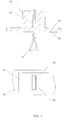
- FIGS. 1A and 1B illustrate a gripper according to a preferred embodiment of the present invention.
- a beam 13 which is part of a carrier assembly (not shown), to be described herebelow.
- grippers 10 On beam 13 are mounted a plurality of gripping assemblies, to be referred to as grippers 10 .
- Each gripper 10 consists of a chuck 14, fixedly attached to beam 13 , and a pair of pinching fingers 12 .
- Each pinching finger 12 is formed as a slightly curved spring blade, made of suitable elastic material -- preferably stainless spring steel, such as type 302/304.
- both blades in a pair are identical and are formed so as to be inter-lockable at one end 16 - for example, as illustrated in Fig. 2A; they are shown interlocked in Fig. 2B.
- Each finger 12 , or blade has, at one end (which is opposite the interlocking end), a tip 11 , which is preferably coated with a soft high-friction substance, such as Neoprene rubber.
- Chuck 14 is preferably made of a durable material, such as Acetal, that has a low but finite factor of friction, and is formed to have an aperture in the form of a slot 15 cut lengthwise therethrough; its length is substantially less than that of fingers 12 .
- chuck 14 may be assembled from two halves, in which slot 15 has been formed on one or both of their joint faces. Slot 15 is formed to slidingly accommodate the assembled pair of fingers 12 .
- Gripper 10 is assembled from the pair of fingers 12, joined back to back (possibly interlocked, as in Fig. 2B) and inserted from above through slot 15 in chuck 14 so that, when they are at the farthest possible insertion depth, their tips 11 substantially protrude and are far apart, as illustrated in Fig.
- fingers 12 The flexible curvature of fingers 12 is such that they tend to push against the faces of slot 15 and thus generate a certain mutual frictional force.
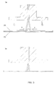
- a foil (e.g. paper) 24 is seen to lie on top of a plate 23 .
- plate 23 is shown lying horizontally, the device of the present invention, as described herein, is similarly applicable for any orientation of the plate.
- fingers 12 are at their lowest position with respect to chuck 14, with tips 11 fully spread, as shown in Fig. 1B.
- Beam 13, with mounted gripper 10 . is lowered until tips 11 touch foil 24 .
- fingers 12 When beam 13 reaches its lowest position, fingers 12 assume a relatively high position with respect to chuck 14, leaving relatively short ends protruding below it. These cause tips 11 to exert maximal pinching force on the portion of foil pinched between them, as illustrated in Fig. 3B, thus gripping the foil.
- the foil can be removed, by moving beam 13 ; owing to the friction between fingers 12 and the chuck 14, the relative position therebetween remains unchanged and thus the foil remains pinched and gripped.
- fingers 12 are pushed maximally down with respect to chuck 14 , by means of a suitable external mechanism. This causes their ends and tips 11 to spread apart, thus releasing the foil.
- the pinching action of the finger tips on the foil is effective over a broad range of foil types and thicknesses and is independent of its structure, such as porosity or face smoothness; moreover, if several sheets of foil lie on the plate, generally all of them are pinched together. It will, thus, be appreciated that a gripper based on such pinching action, which is the primary feature of the present invention, overcomes all three disadvantages of prior art, enumerated in the background section hereabove. It will, further, be appreciated that also other configurations and embodiments of grippers based on such pinching action are possible.
- the tips could be the ends of two members that are made to move mutually by a dedicated activator, this motion being commanded by a sensor that senses the proximity of the foil. It is noted, though, that effecting the pinching action by a mechanism of flexible fingers sliding through a chuck, owing to the reaction of the plate to the tips, as described hereabove, which is another feature of the present invention. represents a very inexpensive and reliable solution.
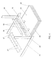
- FIG 4 shows a foil remover according to the present invention, as it may be installed in the feeder portion of a platesetter, we note a stack of fresh plates 25 , with a top plate 23 and, above that, a sheet of foil 24.
- a gantry 26 which is movable along a path generally parallel to the face of plate 23 and perpendicular to the edge 25' -- for example, on tracks 36.
- a disposal station 27 Toward the end of the path is a disposal station 27, consisting primarily of a pair of pinch rollers 27' , oriented parallel to stack edge 25'.
- beam 13 Mounted on vertical tracks on gantry 26 is beam 13, which is movable vertically with respect to the gantry.
- gantry 26 and of beam 13 on their respective tracks is effected by suitable motors or actuators (not shown).
- the assembly of gantry 26 and beam 13 will be referred to as a carrier.
- a plurality of grippers 10 which are each constructed as described hereabove.
- a stopper 28 formed as a horizontally oriented platelet and positioned so that top ends 16 of fingers 12 may butt against it in its upward travel.
- stoppers 28 are stationarily mounted above disposal station 27 , so that when the carrier is at the disposal station, they assume the same positions, relative to the corresponding grippers, as in the first configuration.
- the carrier serves to carry the grippers, which, in turn, serve to grip the foil while the carrier carries it to the disposal station. It will be appreciated that other configurations of the carrier are possible and that all of them are covered by the present invention, as long as the grippers mounted on the carrier are as described herein. Similarly, other configurations of the disposal station are possible.
- Gantry 26 is preferably at or near disposal station 27 , so as to clear the space near stack 25 for plate gripping and feeding.
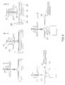
- gantry 26 is moved to position grippers 10 over a section 29 of foil 24 that is near edge 25' , as shown in Fig. 5A.
- Beam 13 is then gradually lowered to its lowest position, thereby causing grippers 10 to pinch foil (or foils) 24 and thus grip section 29 , as shown in Fig. 5B and as explained hereabove.
- Beam 13 is then raised part of the way and not enough for ends 16 of fingers 12 to touch respective stoppers 28; the pinching effect thereby persists and foil section 29 is raised from plate 23 , as shown in Fig. 5C.
- Beam 13 is then lowered part of the way until an edge of sheet 24 is caught by pinch rollers 27' ; these act to pull sheet 24 out from tips 11 of gripper 10 and to deliver it to collection bin 30.
- beam 13 is raised to its highest position, thereby causing upper ends 16 of fingers 12 to butt against corresponding stoppers 28 and thereby to be pushed downward within their respective chucks 14.
- tips 11 are spread apart, and the entire assembly returns to its idling state.
- the last two steps are replaced by the following: beam 13 is raised to its highest position, thereby causing upper ends 16 of fingers 12 to butt against corresponding stoppers 28 and thus -- tips 11 to spread apart, thereby releasing foil section 29. The latter falls toward, and is caught by pinch rollers 27', which transport it, and the rest of sheet (or sheets) 24 , to collection bin 30 .
- the carrier assembly may share components with, or be totally integrated with, the plate picking-and moving mechanism, and yet come within the scope of the present invention; in particular, beam 13 may also have suction cups attached thereto. for picking up and feeding the plates.
Landscapes
- Engineering & Computer Science (AREA)
- Mechanical Engineering (AREA)
- Sheets, Magazines, And Separation Thereof (AREA)
- Advancing Webs (AREA)
Abstract
Description
Claims (11)
- A foil remover apparatus, for removing one or more sheets of foil from an underlying hard surface, comprising a movable carrier and at least one gripper, attached to said carrier, said gripper including a plurality of pinching fingers, each of said fingers oriented approximately perpendicularly to the hard surface and ending with a tip, the foil remover being operative, with respect to each of said grippers, to bring said tips, while mutually apart, in contact with the top sheet of foil and thereupon to cause said tips to approach each other and thereby to pinch any of the sheets.
- A plate feeder apparatus, for feeding plates from a stack of plates to a platesetter or to a printing press, including a foil remover for removing one or more sheets of foil lying over the top plate of the stack, the foil remover comprising a movable carrier and at least one gripper, attached to said carrier, said gripper including a plurality of pinching fingers, each of said fingers oriented approximately perpendicularly to the face of the top plate and ending with a tip, the foil remover being operative, with respect to each of said grippers, to bring said tips, while mutually apart, in contact with the top sheet of foil and thereupon to cause said tips to approach each other and thereby to pinch any of the sheets.
- A foil gripper apparatus, for gripping one or more flexible foils lying on a hard surface, comprising a plurality of pinching fingers, each of said fingers ending with a tip, said foil gripper being operative, after being brought to a position whereby said tips are in contact with the top one of the foils, to cause said tips to approach each other and thereby to pinch the foils.
- The apparatus of any of claims 1 to 3, further comprising a chuck with at least one aperture therethrough and wherein said fingers are elastic and are slidably mounted within said at least one aperture and curved, so that when said fingers slide along said at least one aperture in a first direction such that said tips become nearer said chuck, said tips approach each other, and when said fingers thus slide in an opposite direction, said tips move mutually apart.
- The apparatus of claim 4, wherein the number of said fingers is two, each of said fingers is formed as a blade, the number of said apertures is one or two, and each of said apertures is formed as a slot.
- The apparatus of claim 5, wherein each of said chucks is fixedly attached to said carrier and said carrier is movable along a path that is approximately perpendicular to the hard surface.
- The apparatus of claim 6, further comprising a stopper corresponding to each of said grippers, each of said stoppers being cooperative with said carrier to push said blades of each corresponding one of said grippers in said first direction, thereby causing said tips to separate.
- The apparatus of claim 6, further comprising a disposal station and further operative to move said carrier to said disposal station.
- The apparatus of claim 8, wherein said disposal station includes a pair of pinch rollers, operative to remove any sheets carried by said carrier.
- The apparatus of claim 1, further comprising a plate feeding mechanism, wherein one or more components of said carrier are common to said plate feeding mechanism.
- The apparatus of claim 4 as appendent to claim 3, wherein said fingers are interlocked at one end of each and the number of said apertures is one.
Applications Claiming Priority (2)
| Application Number | Priority Date | Filing Date | Title |
|---|---|---|---|
| IL12169997 | 1997-09-03 | ||
| IL12169997A IL121699A (en) | 1997-09-03 | 1997-09-03 | Foil remover with improved gripper |
Publications (3)
| Publication Number | Publication Date |
|---|---|
| EP0900752A2 true EP0900752A2 (en) | 1999-03-10 |
| EP0900752A3 EP0900752A3 (en) | 1999-12-08 |
| EP0900752B1 EP0900752B1 (en) | 2002-07-03 |
Family
ID=11070597
Family Applications (1)
| Application Number | Title | Priority Date | Filing Date |
|---|---|---|---|
| EP98306224A Expired - Lifetime EP0900752B1 (en) | 1997-09-03 | 1998-08-04 | Foil remover with improved gripper |
Country Status (4)
| Country | Link |
|---|---|
| US (1) | US6164637A (en) |
| EP (1) | EP0900752B1 (en) |
| DE (1) | DE69806313T2 (en) |
| IL (1) | IL121699A (en) |
Cited By (1)
| Publication number | Priority date | Publication date | Assignee | Title |
|---|---|---|---|---|
| EP1055621A3 (en) * | 1999-05-18 | 2001-10-31 | Creo Scitex Corporation Ltd. | An automatic plate feeding system |
Families Citing this family (9)
| Publication number | Priority date | Publication date | Assignee | Title |
|---|---|---|---|---|
| US20030017035A1 (en) | 2000-05-15 | 2003-01-23 | Solomon Yehuda Barnes | Automatic printing plate feeding system |
| US20050067753A1 (en) * | 2003-09-30 | 2005-03-31 | Avi Zahavi | Paper picking system and method |
| DE102004005854B3 (en) * | 2004-02-05 | 2005-03-10 | Erwin Berger | Removal of a protective film from a workpiece or material comprises holding the workpiece so the film is at the top, rubbing a soft plastic over the workpiece and lifting the edge |
| US7685938B2 (en) * | 2004-05-03 | 2010-03-30 | Ecrm Inc. | System for interleaf sheet removal in an imaging system |
| US20080150223A1 (en) * | 2005-12-08 | 2008-06-26 | Todd Kepple | High speed plate pick up device |
| US7607280B2 (en) * | 2006-08-02 | 2009-10-27 | Jacques Dussault | Clamp for sheets of material |
| NL1032357C1 (en) * | 2006-08-23 | 2008-02-26 | Arie Van Der Knijff | Transport device. |
| JP5775364B2 (en) * | 2011-05-30 | 2015-09-09 | 川崎重工業株式会社 | Plate member transfer system with interleaving paper and transfer method thereof |
| US11198577B2 (en) * | 2018-05-04 | 2021-12-14 | Under Armour, Inc. | System and method for picking single sheet of material for further processing |
Family Cites Families (15)
| Publication number | Priority date | Publication date | Assignee | Title |
|---|---|---|---|---|
| DE107649C (en) * | ||||
| US1225740A (en) * | 1915-12-11 | 1917-05-15 | Harris Automatic Press Co | Buckling device. |
| DE2108401C3 (en) * | 1971-02-22 | 1975-04-17 | Stone Manufacturing Co., Greenville, S.C. (V.St.A.) | Device for lifting pieces of fabric from a pile of pieces of fabric |
| DD107649A1 (en) * | 1973-06-29 | 1974-08-12 | ||
| US4019729A (en) * | 1974-05-17 | 1977-04-26 | Cluett, Peabody & Co., Inc. | Apparatus for controllably lowering and lifting a ply picking unit |
| US3940125A (en) * | 1974-05-17 | 1976-02-24 | Cluett, Peabody & Co., Inc. | Picking and transporting means for fabric sections and the like |
| US4157824A (en) * | 1976-04-28 | 1979-06-12 | K. J. Littlewood Pty. Ltd. | Fabric work piece separator |
| US4178097A (en) * | 1977-09-06 | 1979-12-11 | Beach Manufacturing Corporation | Automatic lithographic plate processor |
| DE3025201A1 (en) * | 1980-07-03 | 1982-01-28 | Hoechst Ag, 6000 Frankfurt | DEVICE FOR THE TRANSPORT AND POSITIONING OF PRINTING PLATES |
| US4641827A (en) * | 1983-06-02 | 1987-02-10 | Richard R. Walton | Fabric pickup and the like |
| FR2547801B2 (en) * | 1983-06-24 | 1986-01-03 | Vosgienne Applications Ind | INSTALLATION FOR GRIPPING, TRANSFERRING AND TURNING A TEXTILE TABLECLOTH |
| US4676396A (en) * | 1985-10-11 | 1987-06-30 | Mamolou Charles A | Combined filter housing and extractor therefor |
| IT1213837B (en) * | 1987-10-14 | 1990-01-05 | Solis Srl | TEMPORARY TAKING DEVICE OF KNITTED TEXTILE ITEMS, ESPECIALLY TUBULAR |
| SU1650542A1 (en) * | 1989-02-27 | 1991-05-23 | Каунасский Политехнический Институт Им.А.Снечкуса | Device for separating parts from stack |
| US5018715A (en) * | 1989-09-19 | 1991-05-28 | Red Kap Industries | Fabric pickup device |
-
1997
- 1997-09-03 IL IL12169997A patent/IL121699A/en not_active IP Right Cessation
-
1998
- 1998-08-04 EP EP98306224A patent/EP0900752B1/en not_active Expired - Lifetime
- 1998-08-04 DE DE69806313T patent/DE69806313T2/en not_active Expired - Lifetime
- 1998-08-24 US US09/138,398 patent/US6164637A/en not_active Expired - Lifetime
Cited By (2)
| Publication number | Priority date | Publication date | Assignee | Title |
|---|---|---|---|---|
| EP1055621A3 (en) * | 1999-05-18 | 2001-10-31 | Creo Scitex Corporation Ltd. | An automatic plate feeding system |
| US6422801B1 (en) | 1999-05-18 | 2002-07-23 | Creo Scitex Corporation Ltd. | Automatic plate feeding system |
Also Published As
| Publication number | Publication date |
|---|---|
| US6164637A (en) | 2000-12-26 |
| DE69806313D1 (en) | 2002-08-08 |
| EP0900752B1 (en) | 2002-07-03 |
| DE69806313T2 (en) | 2003-03-06 |
| IL121699A (en) | 2002-12-01 |
| IL121699A0 (en) | 1998-02-22 |
| EP0900752A3 (en) | 1999-12-08 |
Similar Documents
| Publication | Publication Date | Title |
|---|---|---|
| JP3935400B2 (en) | Paper stacking device in paper post-processing device | |
| EP1055621A2 (en) | An automatic plate feeding system | |
| US6164637A (en) | Foil remover with improved gripper | |
| RU2001110378A (en) | SYSTEM OF STORAGE AND DISTRIBUTION OF SHEETS FOR AUTOMATIC BANKING APPARATUS | |
| JPS62121154A (en) | Device for carrying paper bundle | |
| JPH03501473A (en) | Mail bundle band removal method and device | |
| US5623722A (en) | Document set compiler and eject system | |
| US5545000A (en) | Automatic eject finger retractor for document set eject system | |
| CN107697669B (en) | Feed arrangement and image read-out | |
| US6929257B2 (en) | Slip sheet capture mechanism and method of operation | |
| JP3746102B2 (en) | Method and apparatus for separating flats from sediments and its use in tobacco packaging | |
| JP2005067898A (en) | Method and device for sorting paper | |
| US4568073A (en) | Paper handling apparatus for a copier | |
| US6823791B1 (en) | Plate inverter for plate management system and method of operation | |
| US4776575A (en) | Electrophotographic copying apparatus incorporating an automatic adhesive sheet feeding method and apparatus | |
| JP4166895B2 (en) | Device for taking out the inspection sheet from the feeding device of the sheet printing machine | |
| GB2359299A (en) | Vacuum feeder for imaging device | |
| GB2300414A (en) | Continuous stacking of sheets | |
| JPS62290673A (en) | Paper aligner for paper discharge base of printer | |
| JPH11130329A (en) | System of document removal and the like of large capacity delivery stacker of printer | |
| EP0110649B1 (en) | Paper handling apparatus for a copier | |
| US6474640B1 (en) | Method and apparatus for stacking sheets in offset relationship | |
| EP1637323A1 (en) | Plate inverter for plate management system and method of operation | |
| CN220199823U (en) | End plate feeding device | |
| JP2003335425A (en) | Image recording device |
Legal Events
| Date | Code | Title | Description |
|---|---|---|---|
| PUAI | Public reference made under article 153(3) epc to a published international application that has entered the european phase |
Free format text: ORIGINAL CODE: 0009012 |
|
| AK | Designated contracting states |
Kind code of ref document: A2 Designated state(s): BE DE FR GB |
|
| AX | Request for extension of the european patent |
Free format text: AL;LT;LV;MK;RO;SI |
|
| PUAL | Search report despatched |
Free format text: ORIGINAL CODE: 0009013 |
|
| AK | Designated contracting states |
Kind code of ref document: A3 Designated state(s): AT BE CH CY DE DK ES FI FR GB GR IE IT LI LU MC NL PT SE |
|
| AX | Request for extension of the european patent |
Free format text: AL;LT;LV;MK;RO;SI |
|
| RIC1 | Information provided on ipc code assigned before grant |
Free format text: 6B 65H 3/22 A, 6B 65H 3/02 B |
|
| 17P | Request for examination filed |
Effective date: 20000411 |
|
| AKX | Designation fees paid |
Free format text: BE DE FR GB |
|
| 17Q | First examination report despatched |
Effective date: 20000811 |
|
| RAP1 | Party data changed (applicant data changed or rights of an application transferred) |
Owner name: CREOSCITEX CORPORATION LTD. |
|
| GRAG | Despatch of communication of intention to grant |
Free format text: ORIGINAL CODE: EPIDOS AGRA |
|
| GRAG | Despatch of communication of intention to grant |
Free format text: ORIGINAL CODE: EPIDOS AGRA |
|
| GRAG | Despatch of communication of intention to grant |
Free format text: ORIGINAL CODE: EPIDOS AGRA |
|
| GRAH | Despatch of communication of intention to grant a patent |
Free format text: ORIGINAL CODE: EPIDOS IGRA |
|
| GRAH | Despatch of communication of intention to grant a patent |
Free format text: ORIGINAL CODE: EPIDOS IGRA |
|
| GRAA | (expected) grant |
Free format text: ORIGINAL CODE: 0009210 |
|
| RAP1 | Party data changed (applicant data changed or rights of an application transferred) |
Owner name: CREO IL. LTD. |
|
| AK | Designated contracting states |
Kind code of ref document: B1 Designated state(s): BE DE FR GB |
|
| REF | Corresponds to: |
Ref document number: 69806313 Country of ref document: DE Date of ref document: 20020808 |
|
| PG25 | Lapsed in a contracting state [announced via postgrant information from national office to epo] |
Ref country code: BE Free format text: LAPSE BECAUSE OF NON-PAYMENT OF DUE FEES Effective date: 20020831 |
|
| PG25 | Lapsed in a contracting state [announced via postgrant information from national office to epo] |
Ref country code: GB Free format text: LAPSE BECAUSE OF NON-PAYMENT OF DUE FEES Effective date: 20021003 |
|
| ET | Fr: translation filed | ||
| BERE | Be: lapsed |
Owner name: *CREO IL. LTD Effective date: 20020831 |
|
| PLBE | No opposition filed within time limit |
Free format text: ORIGINAL CODE: 0009261 |
|
| STAA | Information on the status of an ep patent application or granted ep patent |
Free format text: STATUS: NO OPPOSITION FILED WITHIN TIME LIMIT |
|
| GBPC | Gb: european patent ceased through non-payment of renewal fee |
Effective date: 20021003 |
|
| 26N | No opposition filed |
Effective date: 20030404 |
|
| PG25 | Lapsed in a contracting state [announced via postgrant information from national office to epo] |
Ref country code: FR Free format text: LAPSE BECAUSE OF NON-PAYMENT OF DUE FEES Effective date: 20030630 |
|
| REG | Reference to a national code |
Ref country code: FR Ref legal event code: ST |
|
| PG25 | Lapsed in a contracting state [announced via postgrant information from national office to epo] |
Ref country code: FR Free format text: LAPSE BECAUSE OF NON-PAYMENT OF DUE FEES Effective date: 20020831 |
|
| PGFP | Annual fee paid to national office [announced via postgrant information from national office to epo] |
Ref country code: DE Payment date: 20120831 Year of fee payment: 15 |
|
| PG25 | Lapsed in a contracting state [announced via postgrant information from national office to epo] |
Ref country code: DE Free format text: LAPSE BECAUSE OF NON-PAYMENT OF DUE FEES Effective date: 20140301 |
|
| REG | Reference to a national code |
Ref country code: DE Ref legal event code: R119 Ref document number: 69806313 Country of ref document: DE Effective date: 20140301 |