EP0900882A2 - Verfahren zur Verkehrslenkung durch Unterflurleuchten sowie Unterflurleuchte und Gruppe von Unterflurleuchten - Google Patents
Verfahren zur Verkehrslenkung durch Unterflurleuchten sowie Unterflurleuchte und Gruppe von Unterflurleuchten Download PDFInfo
- Publication number
- EP0900882A2 EP0900882A2 EP98106342A EP98106342A EP0900882A2 EP 0900882 A2 EP0900882 A2 EP 0900882A2 EP 98106342 A EP98106342 A EP 98106342A EP 98106342 A EP98106342 A EP 98106342A EP 0900882 A2 EP0900882 A2 EP 0900882A2
- Authority
- EP
- European Patent Office
- Prior art keywords
- rows
- led
- lights
- underfloor
- luminaire according
- Prior art date
- Legal status (The legal status is an assumption and is not a legal conclusion. Google has not performed a legal analysis and makes no representation as to the accuracy of the status listed.)
- Granted
Links
Images


Classifications
-
- G—PHYSICS
- G08—SIGNALLING
- G08G—TRAFFIC CONTROL SYSTEMS
- G08G1/00—Traffic control systems for road vehicles
- G08G1/09—Arrangements for giving variable traffic instructions
- G08G1/095—Traffic lights
-
- E—FIXED CONSTRUCTIONS
- E01—CONSTRUCTION OF ROADS, RAILWAYS, OR BRIDGES
- E01F—ADDITIONAL WORK, SUCH AS EQUIPPING ROADS OR THE CONSTRUCTION OF PLATFORMS, HELICOPTER LANDING STAGES, SIGNS, SNOW FENCES, OR THE LIKE
- E01F9/00—Arrangement of road signs or traffic signals; Arrangements for enforcing caution
- E01F9/50—Road surface markings; Kerbs or road edgings, specially adapted for alerting road users
- E01F9/553—Low discrete bodies, e.g. marking blocks, studs or flexible vehicle-striking members
- E01F9/559—Low discrete bodies, e.g. marking blocks, studs or flexible vehicle-striking members illuminated
-
- E—FIXED CONSTRUCTIONS
- E01—CONSTRUCTION OF ROADS, RAILWAYS, OR BRIDGES
- E01F—ADDITIONAL WORK, SUCH AS EQUIPPING ROADS OR THE CONSTRUCTION OF PLATFORMS, HELICOPTER LANDING STAGES, SIGNS, SNOW FENCES, OR THE LIKE
- E01F9/00—Arrangement of road signs or traffic signals; Arrangements for enforcing caution
- E01F9/50—Road surface markings; Kerbs or road edgings, specially adapted for alerting road users
- E01F9/576—Traffic lines
- E01F9/594—Traffic lines movable for reuse at different locations
-
- F—MECHANICAL ENGINEERING; LIGHTING; HEATING; WEAPONS; BLASTING
- F21—LIGHTING
- F21V—FUNCTIONAL FEATURES OR DETAILS OF LIGHTING DEVICES OR SYSTEMS THEREOF; STRUCTURAL COMBINATIONS OF LIGHTING DEVICES WITH OTHER ARTICLES, NOT OTHERWISE PROVIDED FOR
- F21V23/00—Arrangement of electric circuit elements in or on lighting devices
-
- F—MECHANICAL ENGINEERING; LIGHTING; HEATING; WEAPONS; BLASTING
- F21—LIGHTING
- F21W—INDEXING SCHEME ASSOCIATED WITH SUBCLASSES F21K, F21L, F21S and F21V, RELATING TO USES OR APPLICATIONS OF LIGHTING DEVICES OR SYSTEMS
- F21W2111/00—Use or application of lighting devices or systems for signalling, marking or indicating, not provided for in codes F21W2102/00 – F21W2107/00
- F21W2111/06—Use or application of lighting devices or systems for signalling, marking or indicating, not provided for in codes F21W2102/00 – F21W2107/00 for aircraft runways or the like
-
- F—MECHANICAL ENGINEERING; LIGHTING; HEATING; WEAPONS; BLASTING
- F21—LIGHTING
- F21Y—INDEXING SCHEME ASSOCIATED WITH SUBCLASSES F21K, F21L, F21S and F21V, RELATING TO THE FORM OR THE KIND OF THE LIGHT SOURCES OR OF THE COLOUR OF THE LIGHT EMITTED
- F21Y2115/00—Light-generating elements of semiconductor light sources
- F21Y2115/10—Light-emitting diodes [LED]
Definitions
- the invention relates to a method for traffic control, in particular lane change steering, through underfloor lights. Furthermore, the invention relates to an underfloor lamp or a group of underfloor lights for traffic control.
- Underfloor lights of conventional design are with simple light bulbs or halogen lamps. Partly there is one Introduction of light via glass fibers. The are used Underfloor lights also to change lanes for the flowing vehicle traffic. Disadvantages of the existing systems are the short lifespan of the lamps used and the high susceptibility to vibrations and Disorders.
- the object of the present invention is to provide a method for To create traffic control through underfloor lights, one high operational reliability and simple operation guaranteed.
- lights are used as underfloor lights with light emitting diodes (LED) used as lamps.
- the LED show low power consumption with a long service life.
- the Luminous efficiency is relatively high because the light is already strong focused out of the LED and additional reflectors or panels are not required or only to a small extent.
- each other in particular parallel underfloor lights switched together.
- the power consumption of the individual LED is low, so that the switching capacities are easily manageable are. Operation with 24 volts AC enables one fail-safe laying and circuit technology.
- a lane boundary line used multiple rows of underfloor lights the lights of the different rows alternating with each other consequences. If a row fails, for example by one Line damage, the marking of the boundary line remains preserved by the still intact other row.
- An underfloor light according to the invention is by light-emitting diodes (LED) marked as illuminant. These are preferred super bright, yellow LED.
- LED light-emitting diodes
- the underfloor light When supplying the underfloor lights with 24 volt AC voltage is a rectifier circuit in each luminaire Control of the LED provided.
- the underfloor light can be in this version arbitrarily to the available ones Connection lines are connected.
- the LEDs are in a guide block inside the underfloor light used in particular from plastic.
- the Guide block recesses or holes for receiving especially one LED each. With two rows with eight LEDs each there are twice eight holes or recesses in the guide block available.
- the LEDs can also be cast into the guide block be, in particular together with a control circuit.
- the two rows of bores or recesses face each other at an angle of preferably 5 to 30 °, in particular of 8 ° or about 24 °. It is important that by the angle between the rows an overall enlarged light exit angle across the direction of the rows.
- the LED themselves have a light exit angle of preferably 8 ° or 20 ° to 25 °.
- the LEDs are opposite the road level arranged at an angle of 15 ° to 50 °. With two rows LED results in an arrangement of a row under one Angles of about 20 ° and the other row of about 45 ° the road level.
- groups are those described above Underfloor lights used for traffic control. Are there to form a lane line several, in particular two Rows of under-floor lights are provided, the under-floor lights of the different rows alternately on each other consequences.
- the underfloor lights are within a row connected in parallel.
- NF lanes N + 1
- 2x N + 1
- rows of underfloor lights are in common Power supply connected, especially to 24 volts AC voltage.
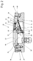
- An underfloor lamp 20 consists of a lower housing 21, an upper cover 22 and one arranged in the housing Lamp insert 23.
- the cover 22 closes an open at the top Room 24 in the housing 21 dust and moisture proof upwards from.
- the lamp insert 23 is arranged in the space 24.
- the housing 21 has an inwardly recessed opening flange 25 on which the cover 22 with an outer circumferential edge 26 comes to rest and by three over the The circumference of the cover bolt 27 with the housing 21 fixed connected is. The inside of the bolt is in the opening flange 25 an annular seal 28 is inserted.
- the lamp insert 23 consists of a guide block 33 Plastic, two rows 34, 35 of light emitting diodes (LED) and one Printed circuit board 36, which is required to control the LED Carries components.
- the guide block 33 is on the cover 22 on two Pins held. These are shown in Fig. 2 only by specifying the Axis 37 indicated and extend obliquely downwards in the Room 24 into it, approximately across the orientation of the LED in the upper row of LEDs 34. Bores 38 can be seen in FIG. 4, with which the guide block 33 is pushed onto the pins becomes. A locking on the pins is preferably not intended. The static friction in the bores 38 is sufficient.
- the upper side 39 of the guide block 33 lies against one for this purpose, parallel inclined surface 40 in the cover 22.
- An opposite underside 41 is on a holding plate 42 supported above the housing base 31.
- the holding plate 42 is with a connection bracket 43 on the housing base 31st screwed and extends obliquely into space 24, approximately parallel to the longitudinal direction of the LED in the upper row of LEDs 34.
- An insulating layer 44 is provided on the holding plate 42 the guide block 33 rests.
- the cover 22 is an approximately rectangular opening 45 through corresponding window glass 46 covered.
- the window glass 46 (also made of plastic, mineral glass or other transparent Fabrics) is glued into the breakthrough and more precisely an inward, circumferential flange 47.
- an adhesive can use a multi-component metal glass adhesive become or another suitable for the materials used Glue.
- the housing 21 and the cover 22 are made preferably made of stainless steel.
- the housing edge 29 closes approximately flush with the Road surface from.
- the cover 22 is partially opposite the level of the pavement.
- the surface 48 of the For this reason, the cover is corrugated all around.
- the surface 48 is also almost divided into two horizontal half 49 and a beveled half 50.
- the window glass 46 is arranged.
- the beveled Half 50 also points transversely to the window glass 46 and webs 51, 52, 53 interrupted by this. Between Ridges are arranged obliquely 54, 55, 56, 57, which extend to the housing edge 29.
- LEDs 58 are arranged here in each row of LEDs 34, 35. Of the Guide block 33 has eight bores 59 accordingly Push the LED 58 through. The individual LED 58 are like this held securely in the guide block 33. There is also over Connection conductor 60 a connection between the LED 58 and the Printed circuit board 36. The latter extends at the end of a Outside 61 of the guide block 33 and carries the (not shown) components for controlling the LED.
- FIGS. 5 to 7 show a modified design of the guide block 62 relative to the guide block 33 in FIGS. 2 to 4.
- the guide block 62 is designed so that on the holding plate 42 can be dispensed with. For this he has an angled one Bottom 63, which rests on the housing base 31 or with an insulation layer 64 against the housing base 31 supports. The insulation layer 64 is glued to the housing base 31.
- Fig. 8 shows a circuit diagram for an underfloor lamp.
- three LED rows 65, 66 and 67 are provided. In every row the LED 58 are connected to each other via a series connection.
- Each row 65, 66, 67 is a series resistor 68, 69, 70 assigned.
- the three rows 65 to 67 are parallel to each other switched and have a common series resistor 71.
- there is a rectifier circuit 72 see above that the individual underfloor lamp operated with AC voltage can be. Exact polarity is therefore not necessary. It is preferably operated with a nominal voltage of 24 volts an underfloor light.
- Rows 75 to 80 of underfloor lights 20 are provided, see 9 and 10. Two rows each form a marking line 81, 82, 83. The underfloor lights are within one line the associated two rows alternately arranged. This means that if a row fails, e.g. due to a line fault, the respective line at least half the brightness consist.
- the individual rows 75 to 80 or lines 81 to 83 are connected in parallel to each other and are attached to one common power supply, in Fig. 9 on the common transformer 84. Instead, several transformers, for example two, three or six transformers can be provided. Is switched the transformer 84 on the primary side via a corresponding bus system, that is not shown here.
- the transformer is made from the usual mains voltage of 230 volts and 50 Hertz powered. Other power supplies are natural possible.
- the transformer can have an uninterruptible power supply be upstream.
- the components mentioned transformer 84, Bus connection and possibly uninterruptible power supply can be arranged in a common switch box 85 be.
- Lines 81 to 83 mark the transfer from the lanes 73, 74 to adjacent lanes 86, 87, see FIG. 10.
- the lines extend for about 250m. Because of the yellow Drivers recognize the color of the LED as a priority opposite the usual white road markings and follow the lines from the lanes 73, 74 to the opposite Lane 86, 87. Due to the construction described a high level of reliability with a high level of maintenance friendliness. If a single LED fails, only the cover 22 unscrewed and the lamp insert 23 replaced with a new one. The polarity of the connections does not have to be changed be noted because the rectifier circuit 72 the Lamp insert 23 is assigned and exchanged with this.
- the lamp insert is in an embodiment not shown 23 with the associated electronics and the guide block 33 in Potted plastic. Also, instead of the described two or three rows with six or eight LEDs each Compilations can be provided. It is important that at Failure of one LED a number of other LEDs of the same underfloor light continues to burn. The light emission from the Underfloor lamp round or square opposite the rectangular one Form of the window glass 46. The individual LEDs are then arranged in a corresponding formation.
- LED 11 and 12 show modifications in the arrangement of the Diodes inside the underfloor light.
- the LED 88 are here held together in a version 89, not shown, together with the control circuit, also not shown.
- the angle between the road level and the LED is about 35 °.
- so-called top LEDs can also be used be used (this naturally also applies to the others Embodiments).
- the socket 89 is in a corresponding insert 90 in the lid 22 held.
- the insert 90 also receives a glass 91 that is designed somewhat differently than the window glass 46 of the above described embodiments.
- the glass 91 is in Beam direction of the LED is much thicker and extends from the LED (or a short distance in front of it) up to one Light exit surface 92 on the top of the lid 22.
- Das Glass 91 is made up of several layers, so that Boundary layers running parallel to the beam direction of the LED result in a total reflection is possible.
- the stratification runs, as I said, in the beam direction of the LED and also transverse to the direction of view according to arrow 93. This is the direction meant the movement of flowing traffic towards corresponds to the underfloor light.
Landscapes
- Engineering & Computer Science (AREA)
- Architecture (AREA)
- Civil Engineering (AREA)
- Structural Engineering (AREA)
- Physics & Mathematics (AREA)
- General Physics & Mathematics (AREA)
- Non-Portable Lighting Devices Or Systems Thereof (AREA)
- Traffic Control Systems (AREA)
- Circuit Arrangement For Electric Light Sources In General (AREA)
Abstract
Description
- Fig. 1
- eine Unterflurleuchte in der Draufsicht,
- Fig. 2
- eine Unterflurleuchte im Querschnitt,
- Fig. 3 und 4
- einen Führungsblock mit zwei Reihen von Leuchtdioden in unterschiedlichen Ansichten,
- Fig. 5
- eine Unterflurleuchte im Querschnitt analog Fig. 2, jedoch mit einer anderen Ausführungsform des Führungsblocks,
- Fig. 6 und 7
- den in Fig. 5 in die Unterflurleuchte eingesetzten Führungsblock in zwei unterschiedlichen Ansichten,
- Fig. 8
- einen Schaltplan für eine Unterflurleuchte,
- Fig. 9
- einen Schaltplan für die Zusammenschaltung mehrerer Reihen von Unterflurleuchten, insbesondere von sechs Reihen zur Darstellung von drei Fahrbahnbegrenzungslinien,
- Fig. 10
- eine Draufsicht auf Fahrspuren mit Spurwechsellenkung,
- Fig. 11
- eine Draufsicht auf eine andere Ausführungsform der Unterflurleuchte,
- Fig. 12
- einen Querschnitt durch die Unterflurleuchte gemäß Fig. 11.
- 20
- Unterflurleuchte
- 21
- Gehäuse
- 22
- Deckel
- 23
- Lampeneinsatz
- 24
- Raum
- 25
- Öffnungsflansch
- 26
- Deckelrand
- 27
- Bolzen
- 28
- Ringdichtung
- 29
- Gehäuserand
- 30
- Bohrungen
- 31
- Gehäuseboden
- 32
- elektrische Durchführung
- 33
- Führungsblock
- 34
- LED-Reihe
- 35
- LED-Reihe
- 36
- Leiterplatte
- 37
- Achse
- 38
- Bohrungen
- 39
- Oberseite
- 40
- Schrägfläche
- 41
- Unterseite
- 42
- Halteblech
- 43
- Anschlußwinkel
- 44
- Dämmschicht
- 45
- Durchbruch
- 46
- Fensterglas
- 47
- Flansch
- 48
- Oberfläche
- 49
- horizontale Hälfte
- 50
- abgeschrägte Hälfte
- 51
- Steg
- 52
- Steg
- 53
- Steg
- 54
- Fläche
- 55
- Fläche
- 56
- Fläche
- 57
- Fläche
- 58
- LED
- 59
- Bohrungen
- 60
- Anschlußleiter
- 61
- Außenseite
- 62
- Führungsblock
- 63
- Unterseite
- 64
- Dämmschicht
- 65
- LED-Reihe
- 66
- LED-Reihe
- 67
- LED-Reihe
- 68
- Vorwiderstand
- 69
- Vorwiderstand
- 70
- Vorwiderstand
- 71
- Vorwiderstand
- 72
- Gleichrichterschaltung
- 73
- Fahrspur
- 74
- Fahrspur
- 75
- Reihe
- 76
- Reihe
- 77
- Reihe
- 78
- Reihe
- 79
- Reihe
- 80
- Reihe
- 81
- Markierungslinie
- 82
- Markierungslinie
- 83
- Markierungslinie
- 84
- Trafo
- 85
- Schaltkasten
- 86
- Fahrspur
- 87
- Fahrspur
- 88
- LED
- 89
- Fassung
- 90
- Einsatz
- 91
- Glas
- 92
- Lichtantrittsfläche
- 93
- Pfeil
Claims (22)
- Verfahren zur Verkehrslenkung, insbesondere Spurwechsellenkung, durch Unterflurleuchten (20), dadurch gekennzeichnet, daß als Unterflurleuchten (20) Leuchten mit Leuchtdioden (LED 58) als Lampen verwendet werden.
- Verfahren nach Anspruch 1, dadurch gekennzeichnet, daß mehrere Reihen (75 bis 80) von insbesondere zueinander parallelen Unterflurleuchten (20) gemeinsam geschaltet werden.
- Verfahren nach Anspruch 1 oder 2, dadurch gekennzeichnet, daß zur Darstellung einer (Fahrbahn-)Markierungslinie (81 bis 83) zwei Reihen (75, 76) bzw. (77, 78) bzw. (79, 80) von Unterflurleuchten (20) verwendet werden, wobei die Leuchten (20) der einen Reihe (75, 77, 79) und der anderen Reihe (76, 78, 80) abwechselnd in derselben Linie angeordnet sind.
- Verfahren nach einem oder mehreren der voranstehenden Ansprüche, dadurch gekennzeichnet, daß die Unterflurleuchten (20) mit Niederspannung, insbesondere mit 24 Volt Wechselspannung betrieben werden.
- Unterflurleuchte, gekennzeichnet durch Leuchtdioden (LED 58) als Lampen.
- Leuchte nach Anspruch 5, dadurch gekennzeichnet, daß als Leuchtdioden (58) insbesondere superhelle, gelbe LED vorgesehen sind.
- Leuchte nach Anspruch 5 oder 6, dadurch gekennzeichnet, daß mehrere LED (58) in Reihe geschaltet und insbesondere mehrere Reihen (65, 66, 67, 34, 35) parallel geschaltet sind, insbesondere zwei Reihen mit je acht LED.
- Leuchte nach Anspruch 5 oder einem der weiteren Ansprüche, gekennzeichnet durch eine Wechselspannungsversorgung, mit insbesondere 24 Volt.
- Leuchte nach Anspruch 5 oder einem der weiteren Ansprüche, gekennzeichnet durch eine Gleichrichterschaltung (72) zwischen Spannungseingang und Reihen (34, 35, 65, 66, 67) von LED.
- Leuchte nach Anspruch 5 sowie einem oder mehreren der weiteren Ansprüche, dadurch gekennzeichnet, daß die LED (58) oder Reihen von LED in einen Führungsblock (33, 62) insbesondere aus Kunststoff eingesetzt oder eingegossen sind.
- Leuchte nach Anspruch 10, dadurch gekennzeichnet, daß der Führungsblock (33, 63) Ausnehmungen oder Bohrungen zur Aufnahme von insbesondere einer LED je Bohrung oder Aufnahme aufweist.
- Leuchte nach Anspruch 10 oder 11, dadurch gekennzeichnet, daß der Führungsblock (33, 63) zur Aufnahme von zwei LED-Reihen (34, 35) zwei Reihen von durchgehenden Bohrungen aufweist.
- Leuchte nach Anspruch 11 oder 12, dadurch gekennzeichnet, daß zwei Reihen von Bohrungen vorgesehen sind, die zueinander unter einem Winkel von vorzugsweise 5° bis 30° stehen, insbesondere 8° oder etwa 24°.
- Leuchte nach Anspruch 5 sowie einem oder mehreren der weiteren Ansprüche, dadurch gekennzeichnet, daß die LED (58) gegenüber einer der Fahrbahnebene entsprechenden Einbauebene unter einem Winkel von 15° bis 50° angeordnet sind.
- Leuchte nach Anspruch 5 sowie einem oder mehreren der weiteren Ansprüche, dadurch gekennzeichnet, daß zwei LED-Reihen (34, 35) vorgesehen sind, wobei eine Reihe (34) unter einem Winkel von etwa 20° und eine Reihe (35) unter einem Winkel von 45° zur Einbauebene bzw. Fahrbahnebene angeordnet ist.
- Leuchte nach Anspruch 5 sowie einem oder mehreren der weiteren Ansprüche, dadurch gekennzeichnet, daß die LED (58) einen Lichtaustrittswinkel von jeweils 8° aufweisen.
- Leuchte nach Anspruch 5 sowie einem oder mehreren der weiteren Ansprüche, dadurch gekennzeichnet, daß die LED (58) einen Lichtaustrittswinkel von jeweils 20° bis 25° aufweisen.
- Gruppe von Unterflurleuchten (20) nach einem oder mehreren der Ansprüche 5 bis 17, zur Verkehrslenkung, insbesondere zur Spurwechsellenkung.
- Gruppe nach Anspruch 18, dadurch gekennzeichnet, daß zur Bildung einer Fahrbahnlinie (Markierungslinie 81, 82, 83) mehrere, insbesondere zwei Reihen (75, 76) bzw. (77, 78) bzw. (79, 80) von Unterflurleuchten (20) vorgesehen sind, wobei die Unterflurleuchten der verschiedenen Reihen innerhalb derselben Markierungslinie abwechselnd aufeinanderfolgen.
- Gruppe nach Anspruch 18 oder 19, dadurch gekennzeichnet, daß die Unterflurleuchten (20) in Reihen (75 bis 80) angeordnet oder geschaltet sind, wobei die Unterflurleuchten (20) innerhalb einer Reihe (75 bis 80) parallel zueinander geschaltet sind.
- Gruppe nach Anspruch 18 sowie einem oder mehreren der weiteren Ansprüche, dadurch gekennzeichnet, daß zur Lenkung von NFahrspuren (N + 1) oder 2x(N + 1) Reihen von Unterflurleuchten (20) vorgesehen sind.
- Gruppe nach Anspruch 18 sowie einem oder mehreren der weiteren Ansprüche, dadurch gekennzeichnet, daß die Reihen (75 bis 80) von Unterflurleuchten (20) an einer gemeinsamen Spannungsversorgung angeschlossen sind, insbesondere an 24 Volt Wechselspannung.
Applications Claiming Priority (2)
| Application Number | Priority Date | Filing Date | Title |
|---|---|---|---|
| DE19739055A DE19739055A1 (de) | 1997-09-05 | 1997-09-05 | Verfahren zur Verkehrslenkung durch Unterflurleuchten sowie Unterflurleuchte und Gruppe von Unterflurleuchten |
| DE19739055 | 1997-09-05 |
Publications (3)
| Publication Number | Publication Date |
|---|---|
| EP0900882A2 true EP0900882A2 (de) | 1999-03-10 |
| EP0900882A3 EP0900882A3 (de) | 2001-03-28 |
| EP0900882B1 EP0900882B1 (de) | 2005-03-16 |
Family
ID=7841434
Family Applications (1)
| Application Number | Title | Priority Date | Filing Date |
|---|---|---|---|
| EP98106342A Expired - Lifetime EP0900882B1 (de) | 1997-09-05 | 1998-04-07 | Verfahren zur Verkehrslenkung durch Unterflurleuchten sowie Unterflurleuchte und Gruppe von Unterflurleuchten |
Country Status (2)
| Country | Link |
|---|---|
| EP (1) | EP0900882B1 (de) |
| DE (2) | DE19739055A1 (de) |
Cited By (2)
| Publication number | Priority date | Publication date | Assignee | Title |
|---|---|---|---|---|
| US6489733B1 (en) | 1998-04-21 | 2002-12-03 | Siemens Aktiengesellschaft | Multi-purpose lighting system for airports, roads or the like |
| EP1233234A3 (de) * | 2001-02-20 | 2005-03-09 | Siemens Aktiengesellschaft | Unterflurfeuer für Signalisierungs- und/oder Markierungszwecke |
Families Citing this family (4)
| Publication number | Priority date | Publication date | Assignee | Title |
|---|---|---|---|---|
| DE20102832U1 (de) | 2001-02-17 | 2001-05-10 | Hess Form & Licht Gmbh & Co | Bodenleuchte für begehbare und/oder befahrbare Flächen |
| DE20202406U1 (de) | 2002-02-15 | 2002-05-08 | Garufo GmbH, 85368 Wang | Leuchteinrichtung |
| DE20205711U1 (de) | 2002-04-11 | 2002-08-22 | aqua signal Aktiengesellschaft Spezialleuchtenfabrik, 28307 Bremen | Unterflurleuchte |
| JP2008223253A (ja) * | 2007-03-09 | 2008-09-25 | Toshiba Lighting & Technology Corp | 埋込形標識灯 |
Family Cites Families (6)
| Publication number | Priority date | Publication date | Assignee | Title |
|---|---|---|---|---|
| US1572214A (en) * | 1924-01-21 | 1926-02-09 | Luther B Mcewing | Road-surface signal lamp |
| US4737764A (en) * | 1986-05-30 | 1988-04-12 | Collins & Aikman Corporation | Modular floor covering units with built-in lighting |
| GB9010215D0 (en) * | 1990-05-05 | 1990-06-27 | Roadstar Markings Ltd | Improvements in or relating to road markers |
| DE4211971A1 (de) * | 1992-02-07 | 1993-08-12 | Deutsche Aerospace | Unterflurfeuer, insbesondere fuer strassen |
| CH686790A5 (fr) * | 1992-04-06 | 1996-06-28 | Paul Donzé | Installation de signalisation routière comprenant au moins une source lumineuse. |
| DE59710923D1 (de) * | 1996-05-23 | 2003-12-04 | Siemens Ag | Leuchteinrichtung für die signalabgabe auf sowie die kennzeichnung und markierung von verkehrsflächen von flughäfen |
-
1997
- 1997-09-05 DE DE19739055A patent/DE19739055A1/de not_active Withdrawn
-
1998
- 1998-04-07 EP EP98106342A patent/EP0900882B1/de not_active Expired - Lifetime
- 1998-04-07 DE DE59812653T patent/DE59812653D1/de not_active Expired - Fee Related
Cited By (2)
| Publication number | Priority date | Publication date | Assignee | Title |
|---|---|---|---|---|
| US6489733B1 (en) | 1998-04-21 | 2002-12-03 | Siemens Aktiengesellschaft | Multi-purpose lighting system for airports, roads or the like |
| EP1233234A3 (de) * | 2001-02-20 | 2005-03-09 | Siemens Aktiengesellschaft | Unterflurfeuer für Signalisierungs- und/oder Markierungszwecke |
Also Published As
| Publication number | Publication date |
|---|---|
| EP0900882A3 (de) | 2001-03-28 |
| EP0900882B1 (de) | 2005-03-16 |
| DE19739055A1 (de) | 1999-03-11 |
| DE59812653D1 (de) | 2005-04-21 |
Similar Documents
| Publication | Publication Date | Title |
|---|---|---|
| EP0898682B1 (de) | Leuchteinrichtung zur signalabgabe, kennzeichnung oder markierung | |
| EP2078895B1 (de) | Leuchtsystem | |
| DE68927279T2 (de) | Schild mit elektrischer Beleuchtung aus einer Niederspannungsquelle | |
| DE102005002783A1 (de) | Beleuchtete Fliese aus Glas | |
| EP1520263A1 (de) | Lichtabgabeeinrichtung, insbesondere verkehrssignal-lichtabgabeeinrichtung, die mit leuchtdioden aufgebaut ist | |
| DE102009058310B4 (de) | LED-Leuchteneinsatz mit Lichtlenkelement | |
| EP0900882B1 (de) | Verfahren zur Verkehrslenkung durch Unterflurleuchten sowie Unterflurleuchte und Gruppe von Unterflurleuchten | |
| DE102010045297A1 (de) | Leuchte, insbesondere Tunnelleuchte | |
| EP2307789A1 (de) | Leuchtmittel mit led | |
| DE102010052852A1 (de) | Straßenleuchte | |
| DE19809253A1 (de) | Unterflurleuchte und Gruppe von Unterflurleuchten | |
| EP1341142B1 (de) | LED- Beleuchtung | |
| DE10300857A1 (de) | Plattenartiges Bekleidungselement, insbesondere für Wände, Decken oder Böden von Gebäuden, und daraus hergestellte Bekleidung | |
| EP1477729A1 (de) | Beleuchtungsvorrichtung für Haltungsanlagen für Geflügel | |
| DE10123006B4 (de) | Leuchtvorrichtung zur Erzeugung einer aktiv nachleuchtenden Signalfläche | |
| DE3843245A1 (de) | Einrichtung zum optischen signalisieren im strassenverkehr | |
| EP3214366B1 (de) | Linearleuchte und verfahren zur montage einer solchen | |
| DE20000502U1 (de) | Beleuchtungseinrichtung für Fussböden | |
| DE202016103572U1 (de) | Modul für eine Leuchte, insbesondere für eine Lichtbandleuchte | |
| DE102016206226B4 (de) | Beleuchtungssystem für Parkleitsysteme | |
| EP3809036A1 (de) | Modulare tunnelbeleuchtungseinrichtung | |
| DE29924584U1 (de) | Flugzeugkabinen-Beleuchtung | |
| DE29602567U1 (de) | Lichtpaneel | |
| EP2400208A2 (de) | Gehwegbeleuchtung | |
| DE202014010179U1 (de) | Ablängbare Einbauleuchte |
Legal Events
| Date | Code | Title | Description |
|---|---|---|---|
| PUAI | Public reference made under article 153(3) epc to a published international application that has entered the european phase |
Free format text: ORIGINAL CODE: 0009012 |
|
| AK | Designated contracting states |
Kind code of ref document: A2 Designated state(s): DE FR GB NL |
|
| AX | Request for extension of the european patent |
Free format text: AL;LT;LV;MK;RO;SI |
|
| PUAL | Search report despatched |
Free format text: ORIGINAL CODE: 0009013 |
|
| AK | Designated contracting states |
Kind code of ref document: A3 Designated state(s): AT BE CH CY DE DK ES FI FR GB GR IE IT LI LU MC NL PT SE |
|
| AX | Request for extension of the european patent |
Free format text: AL;LT;LV;MK;RO;SI |
|
| RIC1 | Information provided on ipc code assigned before grant |
Free format text: 7E 01F 9/06 A, 7E 01F 9/093 B, 7G 08G 1/095 B |
|
| 17P | Request for examination filed |
Effective date: 20010516 |
|
| AKX | Designation fees paid |
Free format text: DE FR GB NL |
|
| 17Q | First examination report despatched |
Effective date: 20030909 |
|
| GRAP | Despatch of communication of intention to grant a patent |
Free format text: ORIGINAL CODE: EPIDOSNIGR1 |
|
| GRAS | Grant fee paid |
Free format text: ORIGINAL CODE: EPIDOSNIGR3 |
|
| GRAA | (expected) grant |
Free format text: ORIGINAL CODE: 0009210 |
|
| AK | Designated contracting states |
Kind code of ref document: B1 Designated state(s): DE FR GB NL |
|
| REG | Reference to a national code |
Ref country code: GB Ref legal event code: FG4D Free format text: NOT ENGLISH |
|
| REF | Corresponds to: |
Ref document number: 59812653 Country of ref document: DE Date of ref document: 20050421 Kind code of ref document: P |
|
| GBT | Gb: translation of ep patent filed (gb section 77(6)(a)/1977) |
Effective date: 20050711 |
|
| PLBE | No opposition filed within time limit |
Free format text: ORIGINAL CODE: 0009261 |
|
| STAA | Information on the status of an ep patent application or granted ep patent |
Free format text: STATUS: NO OPPOSITION FILED WITHIN TIME LIMIT |
|
| 26N | No opposition filed |
Effective date: 20051219 |
|
| ET | Fr: translation filed | ||
| PGFP | Annual fee paid to national office [announced via postgrant information from national office to epo] |
Ref country code: NL Payment date: 20070403 Year of fee payment: 10 |
|
| PGFP | Annual fee paid to national office [announced via postgrant information from national office to epo] |
Ref country code: DE Payment date: 20070421 Year of fee payment: 10 |
|
| PGFP | Annual fee paid to national office [announced via postgrant information from national office to epo] |
Ref country code: GB Payment date: 20070404 Year of fee payment: 10 |
|
| PGFP | Annual fee paid to national office [announced via postgrant information from national office to epo] |
Ref country code: FR Payment date: 20070411 Year of fee payment: 10 |
|
| GBPC | Gb: european patent ceased through non-payment of renewal fee |
Effective date: 20080407 |
|
| NLV4 | Nl: lapsed or anulled due to non-payment of the annual fee |
Effective date: 20081101 |
|
| PG25 | Lapsed in a contracting state [announced via postgrant information from national office to epo] |
Ref country code: NL Free format text: LAPSE BECAUSE OF NON-PAYMENT OF DUE FEES Effective date: 20081101 Ref country code: DE Free format text: LAPSE BECAUSE OF NON-PAYMENT OF DUE FEES Effective date: 20081101 |
|
| REG | Reference to a national code |
Ref country code: FR Ref legal event code: ST Effective date: 20081231 |
|
| PG25 | Lapsed in a contracting state [announced via postgrant information from national office to epo] |
Ref country code: FR Free format text: LAPSE BECAUSE OF NON-PAYMENT OF DUE FEES Effective date: 20080430 |
|
| PG25 | Lapsed in a contracting state [announced via postgrant information from national office to epo] |
Ref country code: GB Free format text: LAPSE BECAUSE OF NON-PAYMENT OF DUE FEES Effective date: 20080407 |