EP0900893A2 - Sytème d'isolation d'éléments de bâtiments contre des émissions polluantes et/ou pour retirer des polluants hors des éléments de construction ainsi que procédé pour extraire des polluants - Google Patents
Sytème d'isolation d'éléments de bâtiments contre des émissions polluantes et/ou pour retirer des polluants hors des éléments de construction ainsi que procédé pour extraire des polluants Download PDFInfo
- Publication number
- EP0900893A2 EP0900893A2 EP98115879A EP98115879A EP0900893A2 EP 0900893 A2 EP0900893 A2 EP 0900893A2 EP 98115879 A EP98115879 A EP 98115879A EP 98115879 A EP98115879 A EP 98115879A EP 0900893 A2 EP0900893 A2 EP 0900893A2
- Authority
- EP
- European Patent Office
- Prior art keywords
- pollutants
- cover
- cover part
- sealing
- air
- Prior art date
- Legal status (The legal status is an assumption and is not a legal conclusion. Google has not performed a legal analysis and makes no representation as to the accuracy of the status listed.)
- Withdrawn
Links
- 238000000034 method Methods 0.000 title claims abstract description 10
- 238000007789 sealing Methods 0.000 title claims description 63
- 239000003344 environmental pollutant Substances 0.000 title claims description 37
- 231100000719 pollutant Toxicity 0.000 title claims description 37
- 239000000463 material Substances 0.000 claims abstract description 37
- 239000004033 plastic Substances 0.000 claims abstract description 15
- 229920003023 plastic Polymers 0.000 claims abstract description 15
- 229910052782 aluminium Inorganic materials 0.000 claims abstract description 11
- XAGFODPZIPBFFR-UHFFFAOYSA-N aluminium Chemical compound [Al] XAGFODPZIPBFFR-UHFFFAOYSA-N 0.000 claims abstract description 11
- 229910052751 metal Inorganic materials 0.000 claims abstract description 10
- 239000002184 metal Substances 0.000 claims abstract description 10
- 238000009792 diffusion process Methods 0.000 claims abstract description 4
- 238000001179 sorption measurement Methods 0.000 claims abstract 10
- 238000005202 decontamination Methods 0.000 claims description 28
- 230000003588 decontaminative effect Effects 0.000 claims description 28
- 238000005192 partition Methods 0.000 claims description 18
- OKTJSMMVPCPJKN-UHFFFAOYSA-N Carbon Chemical compound [C] OKTJSMMVPCPJKN-UHFFFAOYSA-N 0.000 claims description 16
- 239000003054 catalyst Substances 0.000 claims description 7
- 238000004026 adhesive bonding Methods 0.000 claims description 4
- 239000013013 elastic material Substances 0.000 claims description 3
- 238000000926 separation method Methods 0.000 claims description 3
- 239000004698 Polyethylene Substances 0.000 claims description 2
- 229920005830 Polyurethane Foam Polymers 0.000 claims description 2
- VYPSYNLAJGMNEJ-UHFFFAOYSA-N Silicium dioxide Chemical class O=[Si]=O VYPSYNLAJGMNEJ-UHFFFAOYSA-N 0.000 claims description 2
- 239000003463 adsorbent Substances 0.000 claims description 2
- 239000006260 foam Substances 0.000 claims description 2
- 230000002401 inhibitory effect Effects 0.000 claims description 2
- -1 polyethylene Polymers 0.000 claims description 2
- 229920000573 polyethylene Polymers 0.000 claims description 2
- 239000011496 polyurethane foam Substances 0.000 claims description 2
- 239000011347 resin Substances 0.000 claims description 2
- 229920005989 resin Polymers 0.000 claims description 2
- 239000011499 joint compound Substances 0.000 claims 1
- 239000000126 substance Substances 0.000 abstract description 3
- 239000004411 aluminium Substances 0.000 abstract 1
- 239000003570 air Substances 0.000 description 40
- 238000009418 renovation Methods 0.000 description 8
- 239000012790 adhesive layer Substances 0.000 description 7
- 239000010410 layer Substances 0.000 description 6
- 150000003071 polychlorinated biphenyls Chemical class 0.000 description 6
- 239000011888 foil Substances 0.000 description 4
- 238000003795 desorption Methods 0.000 description 3
- 238000010438 heat treatment Methods 0.000 description 3
- 230000001154 acute effect Effects 0.000 description 2
- 239000012080 ambient air Substances 0.000 description 2
- 235000010290 biphenyl Nutrition 0.000 description 2
- 150000004074 biphenyls Chemical class 0.000 description 2
- 238000005265 energy consumption Methods 0.000 description 2
- 238000003780 insertion Methods 0.000 description 2
- 230000037431 insertion Effects 0.000 description 2
- 239000012948 isocyanate Substances 0.000 description 2
- 150000002513 isocyanates Chemical class 0.000 description 2
- 150000003021 phthalic acid derivatives Chemical class 0.000 description 2
- 239000006223 plastic coating Substances 0.000 description 2
- 230000002829 reductive effect Effects 0.000 description 2
- 230000000717 retained effect Effects 0.000 description 2
- 241001295925 Gegenes Species 0.000 description 1
- 239000004831 Hot glue Substances 0.000 description 1
- 230000001464 adherent effect Effects 0.000 description 1
- 239000000853 adhesive Substances 0.000 description 1
- 230000001070 adhesive effect Effects 0.000 description 1
- 230000002009 allergenic effect Effects 0.000 description 1
- 230000009286 beneficial effect Effects 0.000 description 1
- 230000000711 cancerogenic effect Effects 0.000 description 1
- 231100000315 carcinogenic Toxicity 0.000 description 1
- 239000000039 congener Substances 0.000 description 1
- 238000011109 contamination Methods 0.000 description 1
- 230000003111 delayed effect Effects 0.000 description 1
- 230000005489 elastic deformation Effects 0.000 description 1
- 238000003912 environmental pollution Methods 0.000 description 1
- 239000002360 explosive Substances 0.000 description 1
- 230000002349 favourable effect Effects 0.000 description 1
- 238000005187 foaming Methods 0.000 description 1
- 238000003197 gene knockdown Methods 0.000 description 1
- 239000011440 grout Substances 0.000 description 1
- 231100000206 health hazard Toxicity 0.000 description 1
- 238000009434 installation Methods 0.000 description 1
- 239000007788 liquid Substances 0.000 description 1
- 229910044991 metal oxide Inorganic materials 0.000 description 1
- 150000004706 metal oxides Chemical class 0.000 description 1
- 150000002739 metals Chemical class 0.000 description 1
- 230000036961 partial effect Effects 0.000 description 1
- 239000002985 plastic film Substances 0.000 description 1
- 229920006255 plastic film Polymers 0.000 description 1
- 239000004014 plasticizer Substances 0.000 description 1
- 229920001296 polysiloxane Polymers 0.000 description 1
- 230000008929 regeneration Effects 0.000 description 1
- 238000011069 regeneration method Methods 0.000 description 1
- 230000000630 rising effect Effects 0.000 description 1
- 239000000565 sealant Substances 0.000 description 1
- 239000003566 sealing material Substances 0.000 description 1
- 239000007787 solid Substances 0.000 description 1
- 238000010792 warming Methods 0.000 description 1
Images




Classifications
-
- E—FIXED CONSTRUCTIONS
- E04—BUILDING
- E04B—GENERAL BUILDING CONSTRUCTIONS; WALLS, e.g. PARTITIONS; ROOFS; FLOORS; CEILINGS; INSULATION OR OTHER PROTECTION OF BUILDINGS
- E04B1/00—Constructions in general; Structures which are not restricted either to walls, e.g. partitions, or floors or ceilings or roofs
- E04B1/62—Insulation or other protection; Elements or use of specified material therefor
- E04B1/92—Protection against other undesired influences or dangers
Definitions
- the invention relates to a device according to the preamble of the claim 1 or 25 and a method for removing pollutants according to the preamble of claim 36.
- joint material In wall or floor joints, joint material is included, which pollutants, such as B. polychlorinated biphenyls, isocyanates, phthalic acid esters contains that pollute the environment and also carcinogenic and can be allergenic. These pollutants also diffuse into the grouted components.
- pollutants such as B. polychlorinated biphenyls, isocyanates, phthalic acid esters contains that pollute the environment and also carcinogenic and can be allergenic. These pollutants also diffuse into the grouted components.
- PCB polychlorinated Containing biphenyls
- the invention has for its object an uncontrolled Prevent pollutants from escaping into the surrounding area.
- Heating takes place in the decontamination room formed of the component to a temperature at which the vapor pressure of the condensed and the diffused PCB is increased so much that the PCB released into the air in the decontamination room becomes.
- the decontamination room is separated from the rest of the room air by separation.
- the separation should be as airtight and heat insulating as possible be.
- the distance between the partition and the component should be be kept as small as possible to minimize energy consumption.
- the air enriched in the decontaminated room can easily and quickly aspirated and released to the outside air or cleaned be so that the PCB concentration in a simple manner inexpensive can be reduced so much that no health There is a risk to people.
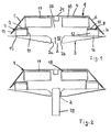
- Fig. 1 shows a device for sealing joint material, in harmful substances, such as polychlorinated biphenyls used as plasticizers in the joint material, isocyanates, Phthalic acid esters and the like are included.
- harmful substances such as polychlorinated biphenyls used as plasticizers in the joint material, isocyanates, Phthalic acid esters and the like are included.
- the establishment can also first then be used when the contaminated joint material for renovation of rooms or buildings has already been removed. With the resulting cavities can be closed off from the device be to prevent residual pollutants in leak the surrounding space and pose a health hazard being able to lead.
- the cover 1 has a shell-like design Cover 1, which on the joint 2 to be sealed Wall 3 is attached.
- the cover 1 has an approximately U-shaped cross section with a flat front wall 4 and obliquely outwards from each other away side walls 5 and 6. They reach in assembled position of the device (Fig. 1) up to close to the wall 3.
- Die Side walls 5 and 6 are profiled on their free longitudinal edges formed such that two chamber-like protruding into the cover 1 Recordings 7 and 8 are formed. These are mirror images of each other trained and have approximately U-shaped cross section.
- you Floor 9, 10 runs parallel to wall 4, and their mutually facing, inner bars 11 and 12 are perpendicular to the Floor 9 or 10.
- the outer bars 13, 14 of the receptacles 7, 8 run at a large obtuse angle to the floor 9 or 10 and close to the side wall with a very small acute angle 5 or 6 of cover 1.
- the shape of the cover part 1 can be chosen differently; e.g. B. the cover can also be used as a curved shell or with any other Desired cross section be formed so that the cover easy on the location and shape of the area to be sealed and be adapted to the corresponding spatial conditions can.
- the cover part 1 is made of gas and diffusion-tight material, such as metal or plastic or one with metal coated plastic, preferably one coated with aluminum Plastic.
- the cover part 1 forms a gas and diffusion tight Lock between the contaminated wall or joint area 2, 3 and the interior of the building.
- the cover 1 gives the device, especially as a result of its profiled side walls 5, 6, the mechanical stability required to set up to attach the wall 3 or another component.
- the Surface of the cover part 1 can be adapted to the existing any desired spatial and / or aesthetic conditions Have color and / or structure.
- the recordings 7, 8 are closed in the direction of the front wall 4 educated. They are used to hold at least one Sealing part 15 and 16, made of permanently elastic material, such as diffusion-inhibiting Foam, e.g. B. polyethylene, or permanently elastic Grout, exists.
- the sealing parts 15, 16 prevent the Gas exchange between the interior of the cover 1 and the Surrounding space.
- the sealing parts 15, 16 are located on both sides of the joint 2 at a distance from her on wall 3.
- the sealing parts 15, 16 are so arranged on the wall 3 that they temperature-related movements can join the wall.
- the closed up Recordings 7, 8 reduce the contact of the sealing part 15, 16 with the room air and the air in the facility to a minimum.
- the Cover part 1 is mounted on the wall 3 so that the sealing parts 15, 16 lay against the wall 3 with elastic deformation. Because of of the inclined legs 13, 14, the sealing parts 15, 16 have little Distance from the floor 9, 10 of the receptacles 7, 8.
- the sealing parts 15, 16 have a rectangular cross section in the exemplary embodiment and extend advantageous over the length of the receptacle 7, 8 or Cover part 1. It is also possible to have two or more sealing parts 15, 16 to put together in this way one over the length of the cover part 1 to achieve continuous sealing.
- the sealing parts 15, 16 are formed by molded parts, which are used in the recordings 7, 8 and in a suitable manner be attached.
- the sealing parts 15, 16 can also by Foaming or filling the receptacles 7, 8 with a sealing material be educated. In this case there is between the bottom 9, 10 the receptacles 7, 8 and the sealing part 15, 16 there is no distance.
- the recordings 7, 8 are in one piece with the embodiment Cover part 1 is formed. But you can also as a separate, with parts to be connected to the cover part.
- Adsorber parts 17, 18 lying apart from one another are provided on the inside of the front wall 4 of the cover 1 . They extend itself from the side walls 5, 6 of the cover 1 at the level of the opposing joint side walls 2a, 2b. In the area between the adsorber parts 17, 18 is on the front wall 4 of the cover part 1, a holding part 21 of a fastening device arranged.
- the adsorber parts 17, 18 are preferably of identical design. she bind the existing pollutants under the cover 1, so they cannot get outside. Via the adsorber parts 17, 18 can exchange the pollutants in a simple manner of the adsorber parts or regeneration.
- the adsorber parts 17, 18 exist z. B. from activated carbon, an adsorber resin, modified silica gel or adsorbent plastics, such as Polyurethane foam.
- the adsorber parts 17, 18 are preferred easily detachably attached to the front wall 4 so that it at Can easily be exchanged and regenerated.
- the adsorber parts 17, 18 have rectangular in the embodiment of FIG. 1 Cross-section and advantageously extend over the length of the cover part 1.
- the adsorber parts 17, 16 put together to cover the length of the cover 1 continuous adsorber parts.
- the adsorber parts 17, 18 each have an air-permeable covering in the exemplary embodiment, in which the adsorber material is located.
- the adsorber parts can also be formed without the envelope.
- FIG. 2 shows, with a sufficiently wide joint 2 at least another adsorber part 19 may be provided. It is beneficial the same design as the adsorber parts 17, 18, but rotated by 90 ° arranged and extends into the joint 2.
- the adsorber 19 is inserted into joint 2 before installing the device.
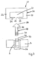
- a fastening device 20 (Fig. 3) provided for fastening the cover part 1 with the adsorber parts 17, 18 and the sealing parts 7, 8 on the wall 3 is a fastening device 20 (Fig. 3) provided. It shows that trained as a rail Holding part 21 on the inside of the front wall 4 of the Cover part 1 is attached centrally, preferably glued.
- the holding rail 21 is preferably made of elastic material. As Fig. 3 shows, it is a c-shaped hollow profile part with a receiving space 27 trained.
- the holding part 21 has mutually parallel Legs 22, 23 whose ends 24, 25 are angled towards each other are. Their free edges are tapered at an acute angle, so that one insertion opening widening outward in cross-section in a V-shape 26 is formed.
- the free ends 24, 25 are at the same height lie, are much thinner than the legs 22, 23. This allows the ends 24, 25 so far elastic when inserting an anchor 28 are bent until the armature 28 engages behind the ends 24, 25. It is therefore sufficient that not the entire holding part 21, but only the leg ends 24, 25 are resilient.
- the armature 28 has a shaft 30 and an armature tip 29 that so is formed that the leg ends 24, 25 in the assembled position engages behind.
- the shaft 30 of the armature 28 is provided with an external thread 31, with which it is screwed into a sleeve 32 with an internal thread 33 can be.
- the sleeve 32 is fastened in a dowel 34, which is advantageous in the joint 2 of the component or the wall 3 is attached.
- the anchor 28 is initially with its shaft 30 in screwed the sleeve 32.
- the anchor height can be stepless in this way can be set precisely. Then the facility can be used the cover part 1, the adsorber parts 17, 18 and the receptacles 7, 8 easily and quickly attached to the wall 3 with the sealing parts 15, 16 become. For this purpose, the device with the holding rail 21 only has to be pressed onto the anchor 28.
- Anchor 28 snaps into the in the manner described in the holding part 21 fastened to the cover part 1 on. As a result, the device is held securely on the wall 3. Of course, there are several over the length of the cover part 1 Anchor 28 is provided to reliably secure the device to the wall 3 to fix.
- the device has an elongated rectangular outline.
- the Sealing parts 15, 16 lie on the long sides and are on the front further sealing parts 15a and 16a connected to each other. she are designed so that they set up on both ends seal. It is also possible to cover both ends of the cover 1 attach a cover to each of the covers on the end faces closes.
- the sealing parts 15a, 16a provided, which are preferably configured and arranged identically are like the sealing parts 15, 16 and advantageously from the same Material like this exist.
- the adsorber parts 17, 18 extend over the entire length between the sealing parts 15a and 16a.
- the Fastening device 20 or the holding part 21 runs between the adsorber parts 17, 18 and ends at a distance from each end sealing parts 15a, 16a.
- the cavity 38 (FIG. 1) of the cover part 1 also be completely filled with adsorber material 39. It is preferable the same material from which the adsorber parts 17, 18 are made.
- To fill the spaces 38 with the adsorber material 39 is one Filling opening 41 is provided. It is used to adsorb material 39 filled in the cover 1.
- the adsorber material 39 is to be regenerated or can be replaced, then it can be through an outlet opening 42 can be emptied again from the cover part 1.
- the openings 41, 42 are located immediately adjacent to the end sealing parts 15a, 16a and approximately symmetrical to the longitudinal center plane of the device. The two openings are in the assembled position of the device 41, 42 arranged at a distance from one another and with a closure, which is preferably detachable.
- the pollutants contained in the joint material diffuse with the Time in the wall areas adjacent to joint 2. For this The reason are the receptacles 7, 8 with the sealing parts 15, 16 in one spaced such that the contaminated, too both sides of the joint 2 located wall areas below the Cover part 1 are in the area between the sealing parts 15, 16. This ensures that the contaminated wall areas escaping pollutants collected by the facility become.
- the device is preferred for sealing in the manner described used by joints. It is of course possible to use the installation of area components that are also contaminated with pollutants, like plates to cover.
- the cover 1 is in such cases no longer as a rail, but rather plate-like with the angled ones Side walls 5, 6 formed.
- the device can also to cover local areas contaminated with pollutants be used.
- the cover part 1 then has a corresponding adapted shape.
- a solid cover that like in the previously described embodiment made of mechanically resistant Material such as metal, plastic or the like is made.
- a coated diffusion-proof layer is used as the sealing part 15b Aluminum foil used. It is attached to wall 3 on site and deformed. Diffusion-tight multiple chambers are formed, which form the receptacles 7b.
- the sealing part 15b consists of three Layers, namely an upper and a lower plastic layer 35 and 36, between which there is an aluminum layer 37.
- the Plastic layers 35, 36 serve to protect the aluminum foil 37.
- Aluminum foil can be used with only one side with a Plastic film is coated.
- an adhesive layer 40 provided, e.g. made of silicone or a hot glue can be.
- Adhesive layer 40 liquefied or if it is still plastically deformable is deformed locally.
- the sealing part 15b are glued to the wall 3 and the diffusion-tight chamber-like receptacles 7b made of aluminum material formed (Fig. 8). The pressure is applied so that the sealing part 15b is meandering in cross section.
- the recordings 7b are like the recordings 7 and 8 of the embodiment of FIG. 1st filled with activated carbon as adsorber material 43. Filling the Recordings 7b with activated carbon are advantageously made in sections.
- the film-like Sealing part the sealing and adsorber function of the adsorber part 15b take over.
- the cover (not shown) serves then only as mechanical protection against damage to the Groove 2. It is preferably glued to wall 3. Using A suitable adhesive layer 40 can also cover the be flat.
- this sealing part 15c in contrast to the sealing part 15b, no plastic layer on. So that this sealing part has sufficient mechanical strength has, it is formed with a profile 75. In the embodiment it is formed by a zigzag fold.
- the sealing part 15c thus formed can be the same as that described above Embodiment compensate for relative movements of the wall 3 and an adsorber material, not shown in FIGS. 9 and 10, such as Activated carbon, take in the folds 76 of the profiling 75.
- an adsorber material not shown in FIGS. 9 and 10
- the counter-holder 28d is in the form of a plate with a circumferential one Plate side 77 protruding edge 78 is formed.
- Half width the counter-holder 28d has a lengthwise extension of the plate, approximately rectangular recess 79. It stretches to about half the length of the counter-holder 28d and is so wide that Legs 80 and 81 are formed on both sides, the width of which is approximately equal is large or slightly smaller than the width of the recess 79.
- a securing part 84 preferably a screw.
- a holding part 21d is provided for connecting the fastening device 20d to the cover 1d. It's through a metal screw formed with a nut 86.
- the holding part 21d is from above an opening (not shown) screwed into the cover 1d, so that the screw head 87 rests on the cover 1d while the screw shaft 88 through the recess 79 between the Legs 80, 81 of the counter-holder 28d protrudes downward.
- a cover 1e is shown, which is very constructive is simple in design and still the necessary flawless Sealing of the component against leakage of pollutants guaranteed.
- This cover 1e serves only as a mechanical one Protection in which the sealing part 15e is provided. It consists of a diffusion-proof film 90. It is covered with an adhesive layer 91 glued to component 3. Joint 2 with adsorber material is advantageous 92 filled. With this cover 1e, the shots can 7,8 (Fig. 1) and their filling with adsorber material are omitted. The arrangement of adsorber parts on the upper wall 4e the cover 1e is not required.
- PCB polychlorinated Containing biphenyls
- the total amount of PCB in the secondary sources is compared to the total amount of PCB in the primary sources, low. So can Joint sealants contain up to 500 g PCB per kg, while the Total amount of PCB in the secondary sources, according to an estimate, can only amount to a few grams. Still affect the secondary sources the current indoor air situation stronger than that Primary sources, which is based on the following.
- the surface of the secondary sources compared to the primary sources is great.
- the PCB of the secondary sources are deposited near the surface and can therefore can be easily released into the air. Because the contamination of the Secondary sources are made via air, they are more volatile Congeners of the PCB, which are also easily released back into the room air can be.
- the process can be accelerated by constantly creating an imbalance state through increased air exchange.
- the desorption is delayed by the fact that PCBs that have diffused into the materials can only be released after a delay.
- the device 1f acc. Fig. 15 has a partition 48, which with Distance from a contaminated surface 44 is arranged, for example PCB is contaminated. To increase efficiency achieve, is the space 49 between the surface 44 and the partition 48 separated from the rest of the room air.
- the partition 48 should be as possible be airtight and heat insulating.
- the distance between the partition 48 and the surface 44 should be as small as possible, to reduce energy consumption.
- the lower edge 48 'of the surface 44 has from the bottom 47 of the corresponding Space small distance, so that a gap 50 is formed over the draft in the direction of arrow P into the decontamination room 49 streams.
- the heat radiators 45, 46 are located at a distance from one another.
- the heat radiator 46 has from the edge 48 the partition 48 larger distance than the heat radiator 45 from top edge 48 "of wall 48.
- Edge 48" has an upper edge Wall 62 of the room 49 distance, so that through the so formed Gap 63 air can escape from the decontamination room 49.
- the device 1f preferably has a pump 51 with which decontaminated air can be sucked in from room 49.
- the pump 51 is preferably connected to the room via a channel 64 49 connected.
- the pump is preferably above the ceiling 65 arranged. There should be negative pressure in decontamination room 49, which is generated by the pump 51 to prevent the leakage of the To ease PCB out of wall 44.
- the surface 44 is heated to the Vapor pressure on the PCB condensed and diffused onto it increase.
- the surface 44 can be targeted with the heat radiators 45, 46 be heated on the surface.
- the temperature is preferably on the surface of surface 44 about 60 ° C to 70 ° C. At a At such a temperature, the vapor pressure increases 50 to 100 times the vapor pressure at 20 ° C.
- Fig. 16 is again made of insulating airtight material existing partition 54 with relative short distance and parallel to the contaminated area 55.
- the partition 54 extends to the bottom 56.
- a line 57 connects to the wall 54 outside of the decontaminated room 53.
- In the line 57 flows from the pump 58 decontaminated air sucked in via an upper Inlet 60 and line 57 to catalyst 59 where they are cleaned becomes. It is then again in the decontaminated via an outlet line 61 Room 53 returned.
- the outlet pipe outlet 61 has a relatively short distance from the floor 56.
- Another one Pump 56 which is like the pump 51 outside the decontamination room 53, the required negative pressure is generated. A part the decontaminated air is pumped into the outside air submitted. This serves to maintain a constant negative pressure in the decontamination room 53 maintain.
Landscapes
- Engineering & Computer Science (AREA)
- Architecture (AREA)
- Physics & Mathematics (AREA)
- Electromagnetism (AREA)
- Civil Engineering (AREA)
- Structural Engineering (AREA)
- Building Environments (AREA)
Applications Claiming Priority (2)
| Application Number | Priority Date | Filing Date | Title |
|---|---|---|---|
| DE1997138567 DE19738567A1 (de) | 1997-09-04 | 1997-09-04 | Einrichtung zur Abdichtung von Bauteilen gegen Schadstoffemissionen |
| DE19738567 | 1997-09-04 |
Publications (2)
| Publication Number | Publication Date |
|---|---|
| EP0900893A2 true EP0900893A2 (fr) | 1999-03-10 |
| EP0900893A3 EP0900893A3 (fr) | 2000-11-02 |
Family
ID=7841102
Family Applications (1)
| Application Number | Title | Priority Date | Filing Date |
|---|---|---|---|
| EP98115879A Withdrawn EP0900893A3 (fr) | 1997-09-04 | 1998-08-22 | Sytème d'isolation d'éléments de bâtiments contre des émissions polluantes et/ou pour retirer des polluants hors des éléments de construction ainsi que procédé pour extraire des polluants |
Country Status (2)
| Country | Link |
|---|---|
| EP (1) | EP0900893A3 (fr) |
| DE (1) | DE19738567A1 (fr) |
Cited By (4)
| Publication number | Priority date | Publication date | Assignee | Title |
|---|---|---|---|---|
| DE102004004979A1 (de) * | 2004-01-31 | 2005-08-18 | Führer, Gerhard, Dr. | Fugenabdichtung als Barriere gegen Mikrooganismen, insbesondere Schimmelpilz, und andere Luftverunreinigungen |
| AT502826B1 (de) * | 2005-11-22 | 2007-06-15 | Pagitsch Paul Ing | Verfahren zur sanierung von wasserschäden, schädlingsbefall, oder dergleichen in gebäuden |
| CN1611931B (zh) * | 2003-10-28 | 2010-08-04 | 梅特勒-托利多公开股份有限公司 | 热分析传感器以及制造热分析传感器的方法 |
| AT519977A4 (de) * | 2017-06-07 | 2018-12-15 | Irsa Christian | Fugenaufbau |
Families Citing this family (1)
| Publication number | Priority date | Publication date | Assignee | Title |
|---|---|---|---|---|
| DE102005031486A1 (de) * | 2005-07-04 | 2007-01-11 | Hülsta-Werke Hüls Gmbh & Co. Kg | Boden-, Wand-, oder Deckenpaneel |
Family Cites Families (2)
| Publication number | Priority date | Publication date | Assignee | Title |
|---|---|---|---|---|
| DE4205035A1 (de) * | 1992-02-19 | 1992-10-01 | Rolf Gerisch | Vorrichtung zum abbau von chemischen verunreinigungen in wand- und deckenverkleidungen aus hoelzern und spanplatten, die mit holzimpraegnierungsmitteln behandelt wurden |
| DE4432834C2 (de) * | 1993-09-17 | 2001-10-18 | Hasso Von Bluecher | Verwendung adsorbierender Materialien zur Sanierung schadstoffbelasteter Räume |
-
1997
- 1997-09-04 DE DE1997138567 patent/DE19738567A1/de not_active Withdrawn
-
1998
- 1998-08-22 EP EP98115879A patent/EP0900893A3/fr not_active Withdrawn
Cited By (6)
| Publication number | Priority date | Publication date | Assignee | Title |
|---|---|---|---|---|
| CN1611931B (zh) * | 2003-10-28 | 2010-08-04 | 梅特勒-托利多公开股份有限公司 | 热分析传感器以及制造热分析传感器的方法 |
| DE102004004979A1 (de) * | 2004-01-31 | 2005-08-18 | Führer, Gerhard, Dr. | Fugenabdichtung als Barriere gegen Mikrooganismen, insbesondere Schimmelpilz, und andere Luftverunreinigungen |
| EP1559843A3 (fr) * | 2004-01-31 | 2006-07-05 | Gerhard Dr. Führer | Joint d'étanchéité comme barrière contre microorganismes, espécialement des moisissures, et d'autres polluants de l'air |
| AT502826B1 (de) * | 2005-11-22 | 2007-06-15 | Pagitsch Paul Ing | Verfahren zur sanierung von wasserschäden, schädlingsbefall, oder dergleichen in gebäuden |
| AT519977A4 (de) * | 2017-06-07 | 2018-12-15 | Irsa Christian | Fugenaufbau |
| AT519977B1 (de) * | 2017-06-07 | 2018-12-15 | Irsa Christian | Fugenaufbau |
Also Published As
| Publication number | Publication date |
|---|---|
| DE19738567A1 (de) | 1999-03-11 |
| EP0900893A3 (fr) | 2000-11-02 |
Similar Documents
| Publication | Publication Date | Title |
|---|---|---|
| EP1440246B1 (fr) | Systeme de montage servant a l'application d'elements de fixation sur une paroi | |
| DE1815460B2 (de) | Vorrichtung zum filtern von in einen raum eintretender luft | |
| DE102008036669B4 (de) | Thermischer Speicherbehälter für einen Innenraum eines Gebäudes | |
| DE60224695T2 (de) | Isolierglasscheibe und deren herstellungsverfahren | |
| EP0609333A1 (fr) | Element de revetement a double paroi et son procede de fabrication | |
| EP0933488A2 (fr) | Grille de plafond pour salles blanches | |
| EP0900893A2 (fr) | Sytème d'isolation d'éléments de bâtiments contre des émissions polluantes et/ou pour retirer des polluants hors des éléments de construction ainsi que procédé pour extraire des polluants | |
| WO2014071905A1 (fr) | Canalisation d'air | |
| DE4321307A1 (de) | Vorrichtung zum Abschotten von durch Wände oder Decken hindurchführenden Rohren | |
| DE4124820C1 (en) | Metal or glass facade or roof - has main glazing bars with sealing strips cut-out to accommodate cross-bars | |
| DE102009031325B4 (de) | Filterwand für raumlufttechnische Anlagen in Gebäuden | |
| EP1918645B1 (fr) | Porte d'un four de cuisson | |
| DE10153618A1 (de) | Backofentür | |
| AT409778B (de) | Verschluss für revisions- und wartungs-öffnungen in bauwerken | |
| DE1910312A1 (de) | Waermeisolierende,insbesondere gasdichte Wandbekleidung sowie Verfahren zum Anbringen desselben | |
| CH600179A5 (en) | Dowel and washer fixing element | |
| DE4321020C2 (de) | Verfahren und Bauelementsatz zur Dämmung einer Wandung einer Leitung | |
| DE3302339C2 (de) | Kabelschutzrohr o.dgl. | |
| DE10034567A1 (de) | Behälter zur Befestigung an einem Fahrzeug | |
| EP0047829A2 (fr) | Dispositif pour la fixation d'objets à des plaques | |
| DE3717020A1 (de) | Verfahren zur oeffnungsfreien herstellung von rohrisolierungen und kaeltegedaemmte rohrleitung | |
| DE2240146A1 (de) | Offene schwerkraft-warmfluessigkeitsheizung, insbesondere fuer wohnwagen | |
| EP1200174B1 (fr) | Filtre a poches, comportant un non-tisse filtrant | |
| DE102024124148A1 (de) | Nasszelle und Freizeitfahrzeug umfassend eine Nasszelle | |
| EP3599316A1 (fr) | Composant léger pour façade et construction de façade dotée d'un tel composant léger pour façade |
Legal Events
| Date | Code | Title | Description |
|---|---|---|---|
| PUAI | Public reference made under article 153(3) epc to a published international application that has entered the european phase |
Free format text: ORIGINAL CODE: 0009012 |
|
| AK | Designated contracting states |
Kind code of ref document: A2 Designated state(s): AT BE CH DE DK FR LI LU NL |
|
| AX | Request for extension of the european patent |
Free format text: AL;LT;LV;MK;RO;SI |
|
| PUAL | Search report despatched |
Free format text: ORIGINAL CODE: 0009013 |
|
| AK | Designated contracting states |
Kind code of ref document: A3 Designated state(s): AT BE CH CY DE DK ES FI FR GB GR IE IT LI LU MC NL PT SE |
|
| AX | Request for extension of the european patent |
Free format text: AL;LT;LV;MK;RO;SI |
|
| RIC1 | Information provided on ipc code assigned before grant |
Free format text: 7E 04C 2/40 A, 7A 62D 3/00 B, 7E 04B 1/92 B |
|
| AKX | Designation fees paid |
Free format text: AT BE CH DE DK FR LI LU NL |
|
| STAA | Information on the status of an ep patent application or granted ep patent |
Free format text: STATUS: THE APPLICATION IS DEEMED TO BE WITHDRAWN |
|
| 18D | Application deemed to be withdrawn |
Effective date: 20010503 |