EP0900896A1 - Vorrichtung zur Befestigung eines Rahmenprofilteils auf Platten, wie zum Beispiel Anzeigetafeln - Google Patents
Vorrichtung zur Befestigung eines Rahmenprofilteils auf Platten, wie zum Beispiel Anzeigetafeln Download PDFInfo
- Publication number
- EP0900896A1 EP0900896A1 EP98402151A EP98402151A EP0900896A1 EP 0900896 A1 EP0900896 A1 EP 0900896A1 EP 98402151 A EP98402151 A EP 98402151A EP 98402151 A EP98402151 A EP 98402151A EP 0900896 A1 EP0900896 A1 EP 0900896A1
- Authority
- EP
- European Patent Office
- Prior art keywords
- piece
- arms
- fixing
- fixing device
- attachment
- Prior art date
- Legal status (The legal status is an assumption and is not a legal conclusion. Google has not performed a legal analysis and makes no representation as to the accuracy of the status listed.)
- Withdrawn
Links
- 238000009432 framing Methods 0.000 title claims 2
- 239000002184 metal Substances 0.000 claims description 35
- 230000000903 blocking effect Effects 0.000 claims description 14
- 238000000465 moulding Methods 0.000 claims description 14
- 125000006850 spacer group Chemical group 0.000 claims description 9
- 230000000295 complement effect Effects 0.000 claims description 8
- 210000000078 claw Anatomy 0.000 description 1
- 238000001816 cooling Methods 0.000 description 1
- 238000005034 decoration Methods 0.000 description 1
- 238000001125 extrusion Methods 0.000 description 1
- 238000009434 installation Methods 0.000 description 1
- 238000012423 maintenance Methods 0.000 description 1
- 238000012986 modification Methods 0.000 description 1
- 230000004048 modification Effects 0.000 description 1
- 239000007787 solid Substances 0.000 description 1
Images


Classifications
-
- G—PHYSICS
- G09—EDUCATION; CRYPTOGRAPHY; DISPLAY; ADVERTISING; SEALS
- G09F—DISPLAYING; ADVERTISING; SIGNS; LABELS OR NAME-PLATES; SEALS
- G09F7/00—Signs, name or number plates, letters, numerals, or symbols; Panels or boards
- G09F7/18—Means for attaching signs, plates, panels, or boards to a supporting structure
-
- E—FIXED CONSTRUCTIONS
- E04—BUILDING
- E04H—BUILDINGS OR LIKE STRUCTURES FOR PARTICULAR PURPOSES; SWIMMING OR SPLASH BATHS OR POOLS; MASTS; FENCING; TENTS OR CANOPIES, IN GENERAL
- E04H17/00—Fencing, e.g. fences, enclosures, corrals
- E04H17/14—Fences constructed of rigid elements, e.g. with additional wire fillings or with posts
- E04H17/16—Fences constructed of rigid elements, e.g. with additional wire fillings or with posts using prefabricated panel-like elements, e.g. wired frames
-
- E—FIXED CONSTRUCTIONS
- E04—BUILDING
- E04H—BUILDINGS OR LIKE STRUCTURES FOR PARTICULAR PURPOSES; SWIMMING OR SPLASH BATHS OR POOLS; MASTS; FENCING; TENTS OR CANOPIES, IN GENERAL
- E04H17/00—Fencing, e.g. fences, enclosures, corrals
- E04H17/14—Fences constructed of rigid elements, e.g. with additional wire fillings or with posts
- E04H17/1413—Post-and-rail fences, e.g. without vertical cross-members
- E04H17/1417—Post-and-rail fences, e.g. without vertical cross-members with vertical cross-members
- E04H17/1426—Picket fences
- E04H17/143—Picket fences with separate pickets attached to the side of the horizontal members
-
- E—FIXED CONSTRUCTIONS
- E04—BUILDING
- E04H—BUILDINGS OR LIKE STRUCTURES FOR PARTICULAR PURPOSES; SWIMMING OR SPLASH BATHS OR POOLS; MASTS; FENCING; TENTS OR CANOPIES, IN GENERAL
- E04H17/00—Fencing, e.g. fences, enclosures, corrals
- E04H17/14—Fences constructed of rigid elements, e.g. with additional wire fillings or with posts
- E04H17/1413—Post-and-rail fences, e.g. without vertical cross-members
- E04H17/1447—Details of connections between rails and posts
Definitions
- the present invention relates to a device for fixing of frame molding on trays of metal, in particular display panels.
- the metal trays are made up of large folded sheet surfaces, with folded edges extended respectively by return wings substantially parallel to the metal plates.
- Different metal trays are arranged edge to edge, so as to constitute the complete panel desired for display, such as a display advertising.
- the periphery of this display panel receives a frame molding intended to give the panel a finish and decoration.
- Fixing devices allow generally both to secure the trays metal two by two and fix the molding coaching.
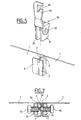
- They include a fastener 30 having two arms 31 adapted to pinch the folded edges adjacent 2 of the metal trays 1.
- This fastener has a tab 33 having a notch 34 adapted for fixing the frame molding 4.
- Each arm 31 has tapped holes 32 suitable for the passage of fixing screws 35 perpendicular to the folded edges.
- the mounting of the fixing part does not can only be done when the frame molding is completely disassembled.
- the object of the present invention is to resolve the aforementioned drawbacks and proposes a device for fixing of metal trays easier to assemble and providing reinforced fixation.
- the tray fixing device metal covered by the invention is intended for trays with a folded edge respectively extended by a return wing substantially parallel to the tray.
- the fixing device comprises a part fastener having two arms adapted to pinch the edges folded down adjacent to two metal trays.
- this device for fixing includes a clamping piece adapted to be fixed on the attachment piece, the return wings of the two metal trays being pinched between the piece clamp and arms of the fastener.
- At least one arm of the piece attachment includes a hollow blocking portion, respectively projecting from a plane of said arm parallel to said return wings of the plates metallic, said clamp comprising additional projecting blocking portions, respectively in hollow, relative to a defined plane by a surface of said clamping piece adapted to be in contact with the return wings, said complementary blocking portions cooperating with said locking portions of the attachment piece for warp the wings back.
- the locking portions allow to deform the return wings of the metal trays in order to form anchor points in the return wings and thus perfect the maintenance of the fixation.
- the attachment piece comprises, in a spacer connecting said arms, a threaded opening adapted to the passage a fixing screw, which is also screwed into a threaded opening of the clamping piece.
- fixation is therefore of greater accessibility and is not hampered by the return wings folded edges of the metal trays.
- the fixing device can also be assembled or disassembled without removing the molding coaching.
- a fixing device allows securing metal trays 1, intended including forming an advertising display panel.
- these metal trays have on their sides longitudinal, in a vertical direction when the trays are mounted, folded edges 2 extended a return wing 3 substantially parallel to the plate metallic.
- folded edges 2 have on one side of the plate a projecting rib 2a intended to cooperate with a hollow rib 2a with a folded edge of the adjacent tray, allowing during assembly, to block the relative movement of the metal plates in a horizontal direction, perpendicular to the vertical plane formed by the plates.
- These metal plates 1 are mounted on 5 feet for fixing the display panel to the ground.
- a frame molding 4 is fixed around the display panels to perfect finishes.
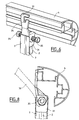
- the device fastener includes a fastener 10 having two arms 11 suitable for pinching adjacent folded edges 2 of two metal trays 1.
- This device comprises a clamping piece 20 adapted to be fixed on the attachment piece 10, the return wings 3 of the two metal plates being pinched between the clamping piece 20 and the arms 11 of the attachment piece 10.
- Each arm 11 of the attachment piece comprises a blocking portion 10 recessed relative to the plane arms 11 parallel to the return wings 3 of the plates metal 1, the clamping piece 20 comprising additional locking portions 23 projecting from relation to a plane defined by the surface of the part of clamping 20 adapted to be in contact with the wings of back 3.
- These complementary blocking portions 23 cooperate with the locking portions 13 to deform the return wings 3, forming a directed bulge to the metal trays 1.
- the attachment piece 10 comprises portions of blocking 13, in the form of an inclined pan, arranged respectively at the free end llb of the arms 11.
- the complementary blocking portions 23 are arranged at one end 21b of the piece of clamping 20 and also have a tilted pan shape 23 formed at the two opposite corners of the end 21b of the clamp 20.
- This clamping piece 20 is thus formed of a flat rectangular piece 21, the two corners 23 of the end 21b of the clamping piece 20 forming two inclined planes to the plane of the room tightening 21.
- the two corners 23 form claws which deform the return wings 3.
- the attachment piece 10 comprises, in a spacer 18 connecting the arms 11, an opening threaded 12 adapted for the passage of a fixing screw 15, further screwed into a threaded opening 22 of the clamp 20.
- the spacer 18 thus forms with the two arms 11 a cavity 14 which spans the folded edges 2 metal trays 1.
- the fixing screw 15 is generally operated by the front face of the panels which is of a greater accessibility.
- the fixing piece 10 further comprises a hanging lug 16 for fixing a molding frame 4 of the metal trays to this piece mounting 10.
- This fixing lug 16 extends from the spacer 18 in an opposite direction from the arms 11 and has an opening 17 adapted to the passage of fixing means, such as a screw for example, which cooperates with the molding 4.
- the fixing device thus designed can be assembled or disassembled without removing the frame molding 4.
- the cavity 14 defined by the facing sides of the arms 11 of the fixing part 10 and the spacer 18 has a width, in a direction perpendicular to the facing faces 11a, higher in a portion adjacent to the free end 11b of the arms than in a portion adjacent to the spacer 18.
- the two facing faces 11a have cut sides at their free end 11b, so that the cavity 14 has a shape, in a vertical plane, of truncated cone flared towards the outside of the cavity 14.
- This particular shape of the cavity 14 allows to facilitate the installation of the fixing piece 10 on the folded edges 2 of the metal plates 1, and the passage of the arms 11 over the nested ribs 2a one inside the other.
- the same model of fixing can be adapted on metal trays with different thicknesses of folded edge 2, for example between 30 and 35 mm, depending on the depth of the ribs 2a of the folded edges 2.
- Fasteners 10 and clamps 20 can be obtained by molding or by extrusion, solid parts of the arms 11 or of the hooking lug 16 then comprising, in a known manner, cavities designed to reduce the excess thickness of parts for promote uniform cooling after molding.
- the inclined planes 13 of the arms 11 of the attachment piece 10 and inclined planes 23 of the piece clamping 20 can be reversed and tilted not more towards the metal plates but towards the rear of the panel, so the return wings 3 are deformed and form a bump towards the outside of folded edges 2.
- these blocking portions 13, 23, may be carried out elsewhere than at the ends of the arm 11 and clamp 20 and form projections and complementary recesses allowing block any relative movement of the plates metallic in their vertical plane.
Landscapes
- Engineering & Computer Science (AREA)
- Architecture (AREA)
- Civil Engineering (AREA)
- Structural Engineering (AREA)
- Physics & Mathematics (AREA)
- General Physics & Mathematics (AREA)
- Theoretical Computer Science (AREA)
- Connection Of Plates (AREA)
- Clamps And Clips (AREA)
Applications Claiming Priority (2)
| Application Number | Priority Date | Filing Date | Title |
|---|---|---|---|
| FR9711083A FR2768198B1 (fr) | 1997-09-05 | 1997-09-05 | Dispositif de fixation de moulure d'encadrement sur des plateaux, tels que des panneaux d'affichage |
| FR9711083 | 1997-09-05 |
Publications (1)
| Publication Number | Publication Date |
|---|---|
| EP0900896A1 true EP0900896A1 (de) | 1999-03-10 |
Family
ID=9510813
Family Applications (1)
| Application Number | Title | Priority Date | Filing Date |
|---|---|---|---|
| EP98402151A Withdrawn EP0900896A1 (de) | 1997-09-05 | 1998-08-31 | Vorrichtung zur Befestigung eines Rahmenprofilteils auf Platten, wie zum Beispiel Anzeigetafeln |
Country Status (2)
| Country | Link |
|---|---|
| EP (1) | EP0900896A1 (de) |
| FR (1) | FR2768198B1 (de) |
Cited By (2)
| Publication number | Priority date | Publication date | Assignee | Title |
|---|---|---|---|---|
| FR2872832A1 (fr) * | 2004-07-12 | 2006-01-13 | Fornells Sa Sa | Dispositif a lice de protection |
| FR2947943A1 (fr) * | 2009-07-07 | 2011-01-14 | Fornells Sa | Profile en materiau extrude pour encadrement de panneau, et cadre correspondant |
Citations (1)
| Publication number | Priority date | Publication date | Assignee | Title |
|---|---|---|---|---|
| FR2617224A1 (fr) * | 1987-06-26 | 1988-12-30 | Fornells Sa | Dispositif d'assemblage de traverses et de bardages au moyen de profiles pour constituer notamment des palissades, des cloisonnements et des parements |
-
1997
- 1997-09-05 FR FR9711083A patent/FR2768198B1/fr not_active Expired - Fee Related
-
1998
- 1998-08-31 EP EP98402151A patent/EP0900896A1/de not_active Withdrawn
Patent Citations (1)
| Publication number | Priority date | Publication date | Assignee | Title |
|---|---|---|---|---|
| FR2617224A1 (fr) * | 1987-06-26 | 1988-12-30 | Fornells Sa | Dispositif d'assemblage de traverses et de bardages au moyen de profiles pour constituer notamment des palissades, des cloisonnements et des parements |
Cited By (3)
| Publication number | Priority date | Publication date | Assignee | Title |
|---|---|---|---|---|
| FR2872832A1 (fr) * | 2004-07-12 | 2006-01-13 | Fornells Sa Sa | Dispositif a lice de protection |
| GB2416131B (en) * | 2004-07-12 | 2008-10-29 | Fornells Sa | A protective barrier device |
| FR2947943A1 (fr) * | 2009-07-07 | 2011-01-14 | Fornells Sa | Profile en materiau extrude pour encadrement de panneau, et cadre correspondant |
Also Published As
| Publication number | Publication date |
|---|---|
| FR2768198A1 (fr) | 1999-03-12 |
| FR2768198B1 (fr) | 1999-11-12 |
Similar Documents
| Publication | Publication Date | Title |
|---|---|---|
| EP1985871B1 (de) | Befestigungssystem von zwei Teilen aufeinander | |
| FR2793741A1 (fr) | Dispositif de fixation d'un radiateur sur un support d'un vehicule | |
| EP0760546B1 (de) | Befestigungsgestell, insbesondere für elektrische Apparate | |
| WO2016124858A1 (fr) | Dispositif de fixation de panneau solaire | |
| EP0592743B1 (de) | Befestigungsvorrichtung zum Zusammenbau von Profilen und damit hergestellte Profilstruktur | |
| FR2659119A1 (fr) | Ecrou en cage perfectionne. | |
| EP0900896A1 (de) | Vorrichtung zur Befestigung eines Rahmenprofilteils auf Platten, wie zum Beispiel Anzeigetafeln | |
| FR2766905A1 (fr) | Profile a rainure(s) pour la mise en place d'au moins un accessoire | |
| EP0762585B1 (de) | Befestigungszubehör zur Montage an ein Gestell, insbesondere für Befestigung von elektrischen Apparaten | |
| WO1989000634A1 (fr) | Dispositif de fixation ponctuelle d'elements presentant un bord, notamment de plaques sur une structure support | |
| FR2583469A1 (fr) | Ecrou encage | |
| FR2548002A1 (fr) | Ensemble cremaillere-console perfectionne destine au rangement avec fixation sur parois | |
| EP0855776A1 (de) | Befestigungsvorrichtung fuer einen elektrischen rohrleiter | |
| EP0169747A1 (de) | Stossdämpfer für Fahrzeug | |
| EP1150409B1 (de) | Kabelrinnenabschnitte und daraus hergestellte Kabelrinne durch Verbinbung von mindestens zwei Abschnitten und deren Herstellungsverfahren | |
| EP0519792B1 (de) | Befestigungsvorrichtung zum Zusammenbau von Profilen und damit hergestellte Profilstruktur | |
| FR2501309A1 (fr) | Profile pour l'assemblage de panneaux | |
| FR2737549A1 (fr) | Brancard inferieur de carrosserie | |
| EP4455429B1 (de) | Sicht- oder verdunkelungspaneel für starre gitterzäune und befestigungsverfahren dafür | |
| FR2916124A1 (fr) | Systeme d'accrochage pour mobilier mural | |
| EP0036686B1 (de) | Feststehender Rahmen | |
| EP0609631A1 (de) | Stell- und Tragevorrichtung für Verblendungsplatten | |
| FR2664633A1 (fr) | Plafond suspendu. | |
| FR2593727A1 (fr) | Hotte d'aeration | |
| EP0340133A1 (de) | Anordnung einer Unterdecke |
Legal Events
| Date | Code | Title | Description |
|---|---|---|---|
| PUAI | Public reference made under article 153(3) epc to a published international application that has entered the european phase |
Free format text: ORIGINAL CODE: 0009012 |
|
| AK | Designated contracting states |
Kind code of ref document: A1 Designated state(s): BE DE ES GB NL |
|
| AX | Request for extension of the european patent |
Free format text: AL;LT;LV;MK;RO;SI |
|
| 17P | Request for examination filed |
Effective date: 19990830 |
|
| AKX | Designation fees paid |
Free format text: BE DE ES GB NL |
|
| STAA | Information on the status of an ep patent application or granted ep patent |
Free format text: STATUS: THE APPLICATION IS DEEMED TO BE WITHDRAWN |
|
| 18D | Application deemed to be withdrawn |
Effective date: 20010301 |