EP0900897A2 - Vorrichtung zum Befestigen von Abschlussleisten - Google Patents
Vorrichtung zum Befestigen von Abschlussleisten Download PDFInfo
- Publication number
- EP0900897A2 EP0900897A2 EP98111379A EP98111379A EP0900897A2 EP 0900897 A2 EP0900897 A2 EP 0900897A2 EP 98111379 A EP98111379 A EP 98111379A EP 98111379 A EP98111379 A EP 98111379A EP 0900897 A2 EP0900897 A2 EP 0900897A2
- Authority
- EP
- European Patent Office
- Prior art keywords
- holding element
- profile
- end strip
- leg
- strips
- Prior art date
- Legal status (The legal status is an assumption and is not a legal conclusion. Google has not performed a legal analysis and makes no representation as to the accuracy of the status listed.)
- Granted
Links
Images


Classifications
-
- E—FIXED CONSTRUCTIONS
- E04—BUILDING
- E04F—FINISHING WORK ON BUILDINGS, e.g. STAIRS, FLOORS
- E04F19/00—Other details of constructional parts for finishing work on buildings
- E04F19/02—Borders; Finishing strips, e.g. beadings; Light coves
- E04F19/04—Borders; Finishing strips, e.g. beadings; Light coves for use between floor or ceiling and wall, e.g. skirtings
- E04F19/0459—Borders; Finishing strips, e.g. beadings; Light coves for use between floor or ceiling and wall, e.g. skirtings characterised by the fixing method
- E04F19/0463—Plinths fixed by snap-action in a direction perpendicular to the wall
-
- A—HUMAN NECESSITIES
- A47—FURNITURE; DOMESTIC ARTICLES OR APPLIANCES; COFFEE MILLS; SPICE MILLS; SUCTION CLEANERS IN GENERAL
- A47B—TABLES; DESKS; OFFICE FURNITURE; CABINETS; DRAWERS; GENERAL DETAILS OF FURNITURE
- A47B77/00—Kitchen cabinets
- A47B77/02—General layout, e.g. relative arrangement of compartments, working surface or surfaces, supports for apparatus
- A47B77/022—Work tops
-
- E—FIXED CONSTRUCTIONS
- E04—BUILDING
- E04F—FINISHING WORK ON BUILDINGS, e.g. STAIRS, FLOORS
- E04F19/00—Other details of constructional parts for finishing work on buildings
- E04F19/02—Borders; Finishing strips, e.g. beadings; Light coves
- E04F19/04—Borders; Finishing strips, e.g. beadings; Light coves for use between floor or ceiling and wall, e.g. skirtings
- E04F19/045—Hygienic or watertight plinths
-
- E—FIXED CONSTRUCTIONS
- E04—BUILDING
- E04F—FINISHING WORK ON BUILDINGS, e.g. STAIRS, FLOORS
- E04F19/00—Other details of constructional parts for finishing work on buildings
- E04F19/02—Borders; Finishing strips, e.g. beadings; Light coves
- E04F19/04—Borders; Finishing strips, e.g. beadings; Light coves for use between floor or ceiling and wall, e.g. skirtings
- E04F2019/0404—Borders; Finishing strips, e.g. beadings; Light coves for use between floor or ceiling and wall, e.g. skirtings characterised by the material
- E04F2019/0413—Borders; Finishing strips, e.g. beadings; Light coves for use between floor or ceiling and wall, e.g. skirtings characterised by the material of metal
Definitions
- the invention relates to a device for fastening End strips, in particular skirting boards, wall connection strips, Ceiling connection strips, transition strips or Like., With a mounting profile for the end strip.
- the strips and profiles can be made within the scope of the invention Plastic, metal or the like. Material exist. Furthermore can also be strips and profile pieces.
- the invention has for its object a device to create which is simple, fast and aligned fastening of end strips without adjustment difficulties to the respective installation conditions guaranteed without the usual tools.
- the invention solves this problem with a generic one Fastening device in that the mounting profile as a U-shaped border profile for one in the U-recess engaging holding element is formed that the one U-leg on the top of the holding element as a double leg is formed to form an insertion groove, and that in the slot the end strip with a Slide-in spring with the formation of a non-shifting Tongue / groove connection can be inserted or vice versa.
- the mounting profile as a U-shaped border profile for one in the U-recess engaging holding element is formed that the one U-leg on the top of the holding element as a double leg is formed to form an insertion groove, and that in the slot the end strip with a Slide-in spring with the formation of a non-shifting Tongue / groove connection can be inserted or vice versa.
- the end strip an insertion groove for receiving the insertion spring to form a tongue and groove connection.
- the holding element is preferably around a holding plate, a floor covering or Carpeting.
- Holding plate means in the context of the invention for example floor plate, ceiling plate, worktop or Like., In particular also laminate panels, as they are increasing Dimensions as floor and ceiling panels or flooring or ceiling cladding are used. Indeed guaranteed within the scope of the invention, the holding plate to be installed, but also a floor slab to be installed, always a perfect fit of the U-shaped border profile without that drilling, screwing, nailing or gluing work is required are.
- floor slabs for example as a holding plate is always a perfect one in advance as well as dirt and moisture repellent seat of the End strip or the skirting board for a base plate without additional drilling, screwing, nailing or gluing guaranteed.
- the end strip or skirting board only with their insertion spring in the insertion groove the mounting bar and then firmly with the floor slab (s) and after laying them connected to the ground.
- worktops with wall connection strips equip, but also ceiling panels, etc. Always the end strip with the intermediary of the border strip directly connected to the respective holding plate.
- the invention provides that the width of the U-recess of the border profile and the thickness of the holding element with the formation of a slip-proof passport or Clamping seat are coordinated.
- the U-recess but can also or additionally as conical towards the opening tapering recess to be formed perfect fit of the border profile on the edge To ensure the holding element.
- the slot as facing the opening be designed tapering groove and regardless of the insertion spring on the end profile a one-step or form a multi-stage rest seat connection.
- the insertion spring of the end strip from one that can be connected to the end strip e.g. B. lockable spring profile is formed, so not part the end bar is.
- the spring profile as an L-shaped profile formed, one of the L-legs in a receiving slot engages on the underside of the end strip and whose other L-leg horizontally from the end strip protrudes so that it is inserted into the insertion groove of the edging profile to be plugged in.
- the U base at the front of the holding elements as Double leg to form a vertical insertion groove educated.
- this is vertical Insertion groove with a molded or separate insertion spring to form a tongue and groove connection insertable or fixable.
- the mounting profile can also be used as a L-shaped border profile for one of the one L-leg overlapped holding element be formed, the one L-leg as double leg to form an insertion groove is formed and in the slot the end strip with an insertion spring to form a Tongue / groove connection can be inserted.
- the double leg on his an underside associated with the holding element, e.g. B. an adhesive tape or double-sided tape.
- an adhesive tape or double-sided tape can be horizontal or vertical Insertion groove can be realized.
- All of the embodiments enable a subsequent Assembly in the course of a sliding technique. From Another particular advantage is the fact that even at new and consequently working floors no cracking fear because the fastening device according to the invention always with the holding element and consequently with a floor covering, a carpet, a holding plate or the like, is consequently independent of that respective floor, which is, for example can trade a concrete floor.
- the fastening device according to the invention always with the holding element and consequently with a floor covering, a carpet, a holding plate or the like, is consequently independent of that respective floor, which is, for example can trade a concrete floor.
- floor cracks not on the invention Transfer fastening system.
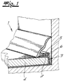
- the mounting profile is U-shaped Socket profile 2 for an engaging in the U-recess 3 Holding element 4 formed.
- the holding element is is a base plate 4 according to the exemplary embodiment, namely laminate board.
- the one U-leg of the Einfberprofils 2 is on the top of the bottom plate 4 as Double leg 5 to form a horizontal Insert groove 6 formed.
- the End strip 1 with an insertion spring 7 with formation a sliding, tongue and groove connection can be inserted or insertable.
- the width of the U-recess 3 of the border profile 2 and the thickness of the bottom plate 4 are under formation a secure fit or a snug fit Voted.
- the U-legs of the U-recess 3 can inside a corrugation or the like. measures to increase friction have what is not shown.
- the slot 6 forms with the insertion spring 7 on the end strip 1 multi-stage rest seat connection, which is only hinted at is.
- the end strip 1 can be assembled as a solid strip are available, in which the Recording slot 10 is incorporated.
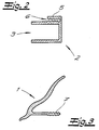
- the insertion spring 7 of the end strip 1 of one with the end strip 1 connectable e.g. B. lockable spring profile 8 is formed.
- the spring profile 8 is designed as an L-shaped profile, whose one L-leg 9 in a receiving slot 10 engages at the bottom of the end strip 1 and whose other L-leg 11 horizontally from the end bar 1 cantilevered and in a socket slot 13 of the socket profile or the holding plate 4 engages.
- the end bar 1 points in the area and above the projecting L-leg 11 a recess 12 for gripping over the relevant Holding plate 4 on.
- the U-base 14 is on the End face of the holding element 4 as a double leg 5 under Formation of a vertical insertion groove 6 is formed.
- this insertion groove 6 is also in this embodiment End strip 1 with a molded or separate insertion spring 7 insertable to form a tongue and groove connection or fixable.
- the mounting profile is as one L-shaped border profile 2 for one of the one L-leg overlapped holding element 4 is formed.
- the one L-leg is as a double leg 5 to form one Insert groove 6 formed.
- the End strip 1 with an insertion spring 7 with formation a tongue and groove connection can be inserted.
- the double leg 5 points to its associated with the holding element 4 Underside of an adhesive coating 15, according to the embodiment a double-sided tape. So far an adhesive connection between the L-shaped border profile 2 and the holding element 4.
- a horizontal insertion groove 6 however, a vertical insertion groove can also be realized.
Landscapes
- Architecture (AREA)
- Engineering & Computer Science (AREA)
- Civil Engineering (AREA)
- Structural Engineering (AREA)
- Floor Finish (AREA)
- Finishing Walls (AREA)
- Adornments (AREA)
- Joining Of Building Structures In Genera (AREA)
- Advancing Webs (AREA)
- Connections Arranged To Contact A Plurality Of Conductors (AREA)
- Vehicle Interior And Exterior Ornaments, Soundproofing, And Insulation (AREA)
- Clamps And Clips (AREA)
- Roof Covering Using Slabs Or Stiff Sheets (AREA)
- Connection Of Plates (AREA)
- Flanged Joints, Insulating Joints, And Other Joints (AREA)
- Processing Of Meat And Fish (AREA)
- Paper (AREA)
Abstract
Description
- Fig. 1
- eine Befestigungsvorrichtung mit Bodenplatte als Halteelement, Einfaßprofil und Sockelleiste als Abschlußleiste ausschnittsweise und in perspektivischer Darstellung,
- Fig. 2
- das Einfaßprofil in Stirnansicht,
- Fig. 3
- das Abschlußprofil bzw. die Sockelleiste in Stirnansicht mit angeformter Einschubfeder,
- Fig. 4
- eine abgewandelte Ausführungsform des Gegenstandes nach Fig. 3 mit L-förmiger Einschubfeder,
- Fig. 5
- die L-förmige Einschubfeder ausschnittsweise und in perspektivischer Darstellung,
- Fig. 6
- eine abgewandelte Ausführungsform des Gegenstandes nach Fig. 4 mit einer von der Abschlußleiste separaten Einschubfeder für einerseits die Abschlußleiste und andererseits das Einfaßprofil,
- Fig. 7
- eine abgewandelte Ausführungsform des Gegenstandes nach Fig. 1 und
- Fig. 8
- eine weitere abgewandelte Ausführungsform des Gegenstandes nach Fig. 1.
Claims (13)
- Vorrichtung zum Befestigen von Abschlußleisten, insbesondere von Sockelleisten, Wandanschlußleisten, Deckenanschlußleisten, Übergangsleisten od. dgl., mit einem Montageprofil für die Abschlußleiste, dadurch gekennzeichnet, daß das Montageprofil als ein U-förmiges Einfaßprofil (2) für ein in die U-Ausnehmung (3) eingreifendes Halteelement (4) ausgebildet ist, daß der eine U-Schenkel auf der Oberseite des Halteelementes (4) als Doppelschenkel (5) unter Bildung einer Einschubnut (6) ausgebildet ist, und daß in die Einschubnut (6) die Abschlußleiste (1) mit einer Einschubfeder (7) unter Bildung einer Nut/Federverbindung einschiebbar ist oder umgekehrt.
- Vorrichtung zum Befestigen von Abschlußleisten, insbesondere von Sockelleisten, Wandanschlußleisten, Deckenanschlußleisten, Übergangsleisten od. dgl., mit einem Montageprofil für die Abschlußleiste, dadurch gekennzeichnet, daß das Montageprofil als ein U-förmiges Einfaßprofil (2) für ein in die U-Ausnehmung (3) eingreifendes Halteelement (4) ausgebildet ist, daß die U-Basis (14) an der Stirnseite des Halteelementes als Doppelschenkel (5) unter Bildung einer Einschubnut (6) ausgebildet ist, und daß in die Einschubnut (6) die Abschlußleiste (1) mit einer Einschubfeder (7) unter Bildung einer Nut/Federverbindung einschiebbar ist oder umgekehrt.
- Vorrichtung nach Anspruch 1 oder 2, dadurch gekennzeichnet, daß die Breite der U-Ausnehmung (3) des Einfaßprofils (2) und die Dicke des Halteelementes (4) unter Bildung eines Paß- oder Klemmsitzes aufeinander abgestimmt sind.
- Vorrichtung nach einem der Ansprüche 1 bis 3, dadurch gekennzeichnet, daß die U-Ausnehmung (3) als sich zur Öffnung hin konisch verjüngende Ausnehmung ausgebildet ist.
- Vorrichtung nach einem der Ansprüche 1 bis 4, dadurch gekennzeichnet, daß die U-Schenkel der U-Ausnehmung (3) innenseitig Widerhaken, eine Riffelung od. dgl. reibungserhöhende Aufrauhungen oder Beschichtungen aufweisen.
- Vorrichtung nach einem der Ansprüche 1 bis 5, dadurch gekennzeichnet, daß das Halteelement (4) als Halteplatte, z. B. Bodenplatte, Deckenplatte, Arbeitsplatte od. dgl. oder Teppichboden ausgebildet ist.
- Vorrichtung nach einem der Ansprüche 1 bis 6, dadurch gekennzeichnet, daß die Einschubnut (6) als sich zur Öffnung hin verjüngende Nut ausgebildet ist.
- Vorrichtung nach einem der Ansprüche 1 bis 7, dadurch gekennzeichnet, daß die Einschubnut (6) mit der Einschubfeder (7) an der Abschlußleiste (1) eine einstufige oder mehrstufige Rastsitzverbindung bildet.
- Vorrichtung nach einem der Ansprüche 1 bis 8, dadurch gekennzeichnet, daß die Einschubfeder (7) der Abschlußleiste (1) von einem mit der Abschlußleiste verbindbaren, z. B. verrastbaren Federprofil (8) gebildet ist.
- Vorrichtung nach einem der Ansprüche 1 bis 9, dadurch gekennzeichnet, daß das Federprofil (8) als L-förmiges Profil ausgebildet ist, dessen einer L-Schenkel (9) in einem Aufnahmeschlitz (10) an der Unterseite der Abschlußleiste (1) eingreift und dessen anderer L-Schenkel (11) waagerecht aus der Abschlußleiste (1) vorkragt und in einen Einfaßschlitz (13) des Halteelements (4) eingreift.
- Vorrichtung nach einem der Ansprüche 1 bis 10, dadurch gekennzeichnet, daß die Abschlußleiste (1) als montagefertige Massivleiste mit dem Aufnahmeschlitz (10) ausgebildet ist.
- Vorrichtung nach einem der Ansprüche 1 bis 11, dadurch gekennzeichnet, daß die Abschlußleiste (1) im Bereich und oberhalb des vorkragenden L-Schenkels (11) eine Ausnehmung (12) zum Übergreifen des Halteelements (4) aufweist.
- Vorrichtung zum Befestigen von Abschlußleisten, insbesondere von Sockelleisten, Wandanschlußleisten, Deckenanschlußleisten, Übergangsleisten od. dgl., mit einem Montageprofil für die Abschlußleiste, dadurch gekennzeichnet, daß das Montageprofil als ein L-förmiges Einfaßprofil (2) für ein von dem einen L-Schenkel übergriffenes Halteelement (4) ausgeführt ist, daß der eine L-Schenkel als Doppelschenkel (5) unter Bildung einer Einschubnut (6) ausgebildet ist, daß in die Einschubnut (6) die Abschlußleiste (1) mit einer Einschubfeder (7) unter Bildung einer Nut/Federverbindung einschiebbar ist oder umgekehrt, und daß der Doppelschenkel (5) auf seiner dem Halteelement (4) zugeordneten Unterseite einen Klebebelag (15), z. B. ein Klebeband oder Doppelklebeband aufweist.
Priority Applications (1)
| Application Number | Priority Date | Filing Date | Title |
|---|---|---|---|
| EP01119992A EP1154098B1 (de) | 1997-09-09 | 1998-06-20 | Abschlussvorrichtung mit einer Abschlussleiste, einem Montageprofil und einem Halteelement |
Applications Claiming Priority (2)
| Application Number | Priority Date | Filing Date | Title |
|---|---|---|---|
| DE29716146U DE29716146U1 (de) | 1997-09-09 | 1997-09-09 | Vorrichtung zum Befestigen von Abschlußleisten |
| DE29716146U | 1997-09-09 |
Related Child Applications (1)
| Application Number | Title | Priority Date | Filing Date |
|---|---|---|---|
| EP01119992A Division EP1154098B1 (de) | 1997-09-09 | 1998-06-20 | Abschlussvorrichtung mit einer Abschlussleiste, einem Montageprofil und einem Halteelement |
Publications (3)
| Publication Number | Publication Date |
|---|---|
| EP0900897A2 true EP0900897A2 (de) | 1999-03-10 |
| EP0900897A3 EP0900897A3 (de) | 1999-06-30 |
| EP0900897B1 EP0900897B1 (de) | 2008-05-21 |
Family
ID=8045727
Family Applications (2)
| Application Number | Title | Priority Date | Filing Date |
|---|---|---|---|
| EP01119992A Expired - Lifetime EP1154098B1 (de) | 1997-09-09 | 1998-06-20 | Abschlussvorrichtung mit einer Abschlussleiste, einem Montageprofil und einem Halteelement |
| EP98111379A Expired - Lifetime EP0900897B1 (de) | 1997-09-09 | 1998-06-20 | Abschlussvorrichtung für Wände, Decken oder Sockel, mit einer Abschlussleiste, einem Montageprofil und einem Halteelement |
Family Applications Before (1)
| Application Number | Title | Priority Date | Filing Date |
|---|---|---|---|
| EP01119992A Expired - Lifetime EP1154098B1 (de) | 1997-09-09 | 1998-06-20 | Abschlussvorrichtung mit einer Abschlussleiste, einem Montageprofil und einem Halteelement |
Country Status (6)
| Country | Link |
|---|---|
| US (1) | US6115982A (de) |
| EP (2) | EP1154098B1 (de) |
| AT (2) | ATE287480T1 (de) |
| CA (1) | CA2244071A1 (de) |
| DE (3) | DE29716146U1 (de) |
| PL (1) | PL200819B1 (de) |
Cited By (7)
| Publication number | Priority date | Publication date | Assignee | Title |
|---|---|---|---|---|
| EP1233119A2 (de) | 2001-02-20 | 2002-08-21 | Ernst Rüsch GmbH | Halteelement für Abdeckleisten |
| EP1359268A2 (de) | 2002-05-04 | 2003-11-05 | Xaver Grünwald GmbH | Vorrichtung zur Befestigung von Sockelleisten |
| WO2005116364A1 (de) | 2004-05-26 | 2005-12-08 | Neuhofer Franz Jun | Vorrichtung zur befestigung einer abschlussleiste |
| WO2006105956A1 (de) | 2005-04-05 | 2006-10-12 | Karl Pedross Ag | Vorrichtung zum befestigen von abschlussleisten |
| EP2549032A1 (de) * | 2011-07-18 | 2013-01-23 | Tode Management BVBA | Abschlussverkleidungsprofil für eine zu verkleidende Fläche |
| US8640390B2 (en) | 2010-01-25 | 2014-02-04 | Schlueter-Systems Kg | Decorative strip for showers |
| EP4717849A1 (de) | 2024-09-30 | 2026-04-01 | Döllken Profiles GmbH | Sockelleiste |
Families Citing this family (62)
| Publication number | Priority date | Publication date | Assignee | Title |
|---|---|---|---|---|
| DE29716146U1 (de) * | 1997-09-09 | 1997-11-20 | W. Döllken & Co. GmbH, 45239 Essen | Vorrichtung zum Befestigen von Abschlußleisten |
| DE20001203U1 (de) | 2000-01-25 | 2000-05-18 | W. Döllken & Co. GmbH, 45239 Essen | Transparente Wandanschlussleiste mit austauschbarem Dekorstreifen |
| USD473662S1 (en) | 2001-02-14 | 2003-04-22 | Certainteed Corporation | Detachable lineal for doors and windows |
| US6550192B1 (en) * | 2001-02-14 | 2003-04-22 | Richard C. Nelson | Transition molding |
| US6625941B2 (en) * | 2001-02-14 | 2003-09-30 | Certainteed Corporation | Detachable lineal for doors and windows |
| US7055918B2 (en) * | 2001-07-27 | 2006-06-06 | Lachance James L | Attachment element for joining a backplash to a countertop |
| US6729088B2 (en) | 2002-02-05 | 2004-05-04 | Shannon L. Corr | Positioning jig for installing molding |
| US6918212B1 (en) * | 2002-07-23 | 2005-07-19 | Andy W. Anderson, Sr. | Seamed/seamless fabric wall panel system |
| US20040026679A1 (en) * | 2002-08-01 | 2004-02-12 | Terrels Christopher J. | Post and railing construction |
| US20040206028A1 (en) * | 2002-08-01 | 2004-10-21 | Terrels Christopher J. | Railing system and support assembly |
| US7243473B2 (en) * | 2002-08-06 | 2007-07-17 | Terrels Christopher J | Post assembly and trim ring |
| US6883288B1 (en) * | 2002-09-24 | 2005-04-26 | Todd Harbin | J-channel |
| USD474055S1 (en) | 2002-09-27 | 2003-05-06 | Arthur Brewster | Backsplash |
| BE1015275A3 (nl) * | 2003-01-07 | 2004-12-07 | Flooring Ind Ltd | Klemelement voor plinten. |
| USD483883S1 (en) | 2003-02-25 | 2003-12-16 | Duramax, Inc. | Wall base with semicircular interior voids |
| USD483884S1 (en) | 2003-02-25 | 2003-12-16 | Duramax, Inc. | Wall base with interior structure |
| USD484254S1 (en) | 2003-02-25 | 2003-12-23 | Duramax, Inc. | Wall base with curved front face and flat back face |
| USD484253S1 (en) | 2003-02-25 | 2003-12-23 | Duramax, Inc. | Wall base with notch in front face |
| USD483881S1 (en) | 2003-02-25 | 2003-12-16 | Duramax, Inc. | Wall base with curved back face |
| USD483882S1 (en) | 2003-02-25 | 2003-12-16 | Duramax, Inc. | Wall base with three steps |
| USD662410S1 (en) | 2003-08-01 | 2012-06-26 | Railing Dynamics, Inc. | Insert for concealing a fastener hole |
| US20050224777A1 (en) * | 2004-04-13 | 2005-10-13 | Terrels Christopher J | Connector fitting for railing components |
| US7712263B1 (en) * | 2004-08-02 | 2010-05-11 | Randall Lippie | Bird repellant device |
| USD521656S1 (en) | 2004-09-28 | 2006-05-23 | Terrels Christopher J | Adjustable cladding assembly |
| US8640397B2 (en) | 2005-03-21 | 2014-02-04 | Bird-B-Gone, Inc. | Adjustable bird slope |
| CA110757S (en) * | 2005-04-15 | 2008-02-12 | Carney Timber Company | Edge board member |
| US20060242916A1 (en) * | 2005-05-02 | 2006-11-02 | Carney Timber Company | Edge boards and related assemblies |
| US20060283110A1 (en) * | 2005-06-20 | 2006-12-21 | K & T Stoneworks, Inc. | Secure bracket for rapid installation |
| DE102007002592B3 (de) * | 2007-01-12 | 2008-07-24 | Joecks, Martin, Dipl.-Ing. | Haltevorrichtung zur Halterung einer Fußbodenleiste |
| US7731160B2 (en) * | 2007-09-28 | 2010-06-08 | Railing Dynamics, Inc. | Post and railing assembly with support bracket covers |
| US20090108719A1 (en) * | 2007-10-26 | 2009-04-30 | Klickit Products, L.L.C. | Apparatus and method for attaching a backsplash to a countertop |
| US8147009B1 (en) * | 2007-11-30 | 2012-04-03 | Rider H Joe | Cabinet component system |
| US20090293392A1 (en) * | 2008-05-22 | 2009-12-03 | Tim Dykstra | Moulding Assembly |
| AT507336B1 (de) | 2008-09-25 | 2010-07-15 | Neuhofer Franz Jun | Vorrichtung zur befestigung einer abschlussleiste |
| US8079186B2 (en) * | 2008-12-22 | 2011-12-20 | Douglas Williams | Soffit system |
| US8074411B1 (en) | 2009-09-11 | 2011-12-13 | Andrew Jacob Anderson | Fabric wall panel and track |
| PL220426B1 (pl) * | 2009-11-26 | 2015-10-30 | Adam Sławomir Galas | Zestaw mocujący listwy |
| ITMI20111192A1 (it) * | 2011-06-29 | 2012-12-30 | Essea S A S Di Spinelli Antonio | Dispositivo di apertura di un elemento di arredo |
| WO2013006975A2 (en) * | 2011-07-11 | 2013-01-17 | Cory Halischuk | Fastening a ceiling trim |
| US8813623B2 (en) * | 2011-08-22 | 2014-08-26 | Gregory Scott Armacost | Assembly for coping and mounting trim molding |
| TWM424610U (en) * | 2011-11-25 | 2012-03-11 | Hulk Energy Technology Co Ltd | Frame structure of solar energy module (1) |
| WO2013142596A2 (en) * | 2012-03-20 | 2013-09-26 | Rtc Industries, Inc. | Shelf gap spacer device for a merchandise display system |
| US9151061B2 (en) | 2012-10-05 | 2015-10-06 | Fiber Cement Foam Systems Insulation, LLC | Method and a device to attach building trims |
| US9027299B2 (en) * | 2013-07-12 | 2015-05-12 | Joseph Mea | Themed modular ceiling and wall decor kit and system |
| USD919839S1 (en) | 2013-12-19 | 2021-05-18 | VPI Corporation | Wall base with angled top |
| US9303414B1 (en) * | 2014-02-10 | 2016-04-05 | Daryl B. Keiser | Grain bin bolt cover |
| AT515906B1 (de) * | 2014-07-18 | 2016-01-15 | Neuhofer Franz Jun | Vorrichtung zum Befestigen einer Abschlussleiste an einer Wand |
| USD809676S1 (en) | 2016-02-25 | 2018-02-06 | VPI Corporation | Wall base with groove and curved lower section |
| PL232410B1 (pl) * | 2016-04-05 | 2019-06-28 | Adam Galas | Sprężysta obejma i zestaw listwy przypodłogowej ze sprężystą obejmą |
| DE202016102498U1 (de) | 2016-05-10 | 2016-05-30 | Engeltech Gmbh | Werkzeuglos montierbare Abschlussleiste und Vorrichtung dazu |
| DE202017102750U1 (de) | 2017-02-17 | 2017-06-07 | Engeltech Gmbh | Vorrichtung zur werkzeuglosen Montage einer Abschlussleiste |
| US20190119911A1 (en) * | 2017-10-25 | 2019-04-25 | War Bird Manufacturing, Inc. | Bird exclusion device |
| CA3117836A1 (en) * | 2018-10-29 | 2020-05-07 | Donald J. Fletcher | Floor edge moulding with wall-taped mounting and pinched floor retention |
| US10900243B2 (en) * | 2019-05-24 | 2021-01-26 | Terry Koethe | Two-piece trim assembly for siding on buildings |
| US10834915B1 (en) * | 2019-09-05 | 2020-11-17 | Paul Tamulewicz | Avian nesting deterrent |
| DE202020101320U1 (de) | 2020-03-10 | 2021-06-11 | Wolfgang Engel | Montageclip für Sockelleisten mit wandseitiger Sperrfunktion |
| DE202020101330U1 (de) | 2020-03-11 | 2021-06-15 | Wolfgang Engel | Montageclip für Sockelleisten mit bodenbelagseitiger Sperrfunktion |
| DE202020102369U1 (de) | 2020-04-28 | 2020-05-29 | Hilmar Kusmierz | Sockelprofil |
| RU203441U1 (ru) * | 2021-01-21 | 2021-04-05 | Александр Михайлович Кузнецов | Плинтус |
| CA3172914C (en) * | 2022-09-09 | 2023-10-24 | Alumax Panel Inc. | Extrusion profile bracket for panel mounting |
| GB202215371D0 (en) * | 2022-10-18 | 2022-11-30 | Window Widgets Ltd | Door and window trim clip |
| US12390023B2 (en) * | 2024-01-30 | 2025-08-19 | Walmart Apollo, Llc | Backstop for shelving unit |
Family Cites Families (18)
| Publication number | Priority date | Publication date | Assignee | Title |
|---|---|---|---|---|
| BE663722A (de) * | 1951-01-28 | 1900-01-01 | ||
| US3007213A (en) * | 1955-02-14 | 1961-11-07 | Colotrym Company | Junction molding |
| CA898481A (en) * | 1969-12-08 | 1972-04-25 | Bernard Harby Limited | Wall base member |
| US3667177A (en) * | 1970-05-08 | 1972-06-06 | Elmer G Biela | Molding joints and universal molding members therefor |
| DE2110312A1 (de) * | 1971-03-04 | 1972-09-14 | Zech, Klaus, 2300 Kiel | Putz und Estrichlehre Typ Kiel als Bauelement und Fussleistenträger |
| DE2123154A1 (de) * | 1971-05-11 | 1972-11-16 | Fa. Wilhelm Schade, 5970 Plettenberg | Vorrichtung zum Abdecken von Raumkanten |
| FR2456246B1 (fr) * | 1979-05-08 | 1985-11-08 | Bobath Peter | Dispositif pour joindre bord a bord des panneaux |
| GB2115692A (en) * | 1981-09-02 | 1983-09-14 | Holden Hydroman Limited | Carpet fasteners |
| GB8621049D0 (en) * | 1986-08-30 | 1986-10-08 | Merry G S | Sealing junction between wall & floor |
| GB2227935A (en) * | 1989-02-10 | 1990-08-15 | Colin Stephen Pownall | Floor-covering edge seal |
| FR2660348B1 (fr) * | 1990-03-30 | 1992-07-31 | Tomecanic Sa | Profile destine notamment a la compensation des deplacements relatifs d'un revetement de sol par rapport a un mur adjacent. |
| US5079880A (en) * | 1990-06-15 | 1992-01-14 | Eugene Reid | Trim for covering and securing dry wall adjacent to surrounding portion of a bathtub or shower stall |
| GB2253222B (en) * | 1991-02-27 | 1995-03-22 | Austin Charles Murphy | Tile trim |
| DE9421899U1 (de) * | 1994-11-09 | 1997-02-06 | Alfer-Aluminium GmbH, 79793 Wutöschingen | Fugenabdeckvorrichtung |
| CA2138071A1 (en) * | 1994-12-14 | 1996-06-15 | Helmut Schmidt | Multi part plastic lineal |
| US5829206A (en) * | 1997-04-25 | 1998-11-03 | Douglass Bachman | Top panel snap-in trim for exterior siding |
| US5836113A (en) * | 1997-04-25 | 1998-11-17 | Douglass Bachman | System and method of securing and finishing exterior siding panels |
| DE29716146U1 (de) * | 1997-09-09 | 1997-11-20 | W. Döllken & Co. GmbH, 45239 Essen | Vorrichtung zum Befestigen von Abschlußleisten |
-
1997
- 1997-09-09 DE DE29716146U patent/DE29716146U1/de not_active Expired - Lifetime
-
1998
- 1998-06-20 EP EP01119992A patent/EP1154098B1/de not_active Expired - Lifetime
- 1998-06-20 AT AT01119992T patent/ATE287480T1/de not_active IP Right Cessation
- 1998-06-20 DE DE59812505T patent/DE59812505D1/de not_active Expired - Lifetime
- 1998-06-20 AT AT98111379T patent/ATE396312T1/de not_active IP Right Cessation
- 1998-06-20 EP EP98111379A patent/EP0900897B1/de not_active Expired - Lifetime
- 1998-06-20 DE DE59814234T patent/DE59814234D1/de not_active Expired - Lifetime
- 1998-07-03 PL PL327221A patent/PL200819B1/pl not_active IP Right Cessation
- 1998-09-04 CA CA002244071A patent/CA2244071A1/en not_active Abandoned
- 1998-09-09 US US09/149,963 patent/US6115982A/en not_active Expired - Fee Related
Cited By (12)
| Publication number | Priority date | Publication date | Assignee | Title |
|---|---|---|---|---|
| EP1233119A2 (de) | 2001-02-20 | 2002-08-21 | Ernst Rüsch GmbH | Halteelement für Abdeckleisten |
| EP1233119A3 (de) * | 2001-02-20 | 2002-12-18 | Ernst Rüsch GmbH | Halteelement für Abdeckleisten |
| DE10107864C2 (de) * | 2001-02-20 | 2003-06-12 | Ernst Ruesch Gmbh | Halteelement für Abdeckleisten |
| US6643987B2 (en) | 2001-02-20 | 2003-11-11 | Ernst Rüsch GmbH | Supporting element for cover strips |
| EP1359268A2 (de) | 2002-05-04 | 2003-11-05 | Xaver Grünwald GmbH | Vorrichtung zur Befestigung von Sockelleisten |
| WO2005116364A1 (de) | 2004-05-26 | 2005-12-08 | Neuhofer Franz Jun | Vorrichtung zur befestigung einer abschlussleiste |
| WO2006105956A1 (de) | 2005-04-05 | 2006-10-12 | Karl Pedross Ag | Vorrichtung zum befestigen von abschlussleisten |
| US7594368B2 (en) | 2005-04-05 | 2009-09-29 | Karl Pedross Ag | Device for fastening termination strips |
| US8640390B2 (en) | 2010-01-25 | 2014-02-04 | Schlueter-Systems Kg | Decorative strip for showers |
| EP2549032A1 (de) * | 2011-07-18 | 2013-01-23 | Tode Management BVBA | Abschlussverkleidungsprofil für eine zu verkleidende Fläche |
| EP4717849A1 (de) | 2024-09-30 | 2026-04-01 | Döllken Profiles GmbH | Sockelleiste |
| DE102024128222A1 (de) * | 2024-09-30 | 2026-04-02 | Döllken Profiles GmbH | Sockelleiste |
Also Published As
| Publication number | Publication date |
|---|---|
| EP0900897A3 (de) | 1999-06-30 |
| EP0900897B1 (de) | 2008-05-21 |
| EP1154098A2 (de) | 2001-11-14 |
| ATE396312T1 (de) | 2008-06-15 |
| ATE287480T1 (de) | 2005-02-15 |
| EP1154098B1 (de) | 2005-01-19 |
| PL327221A1 (en) | 1999-03-15 |
| DE59812505D1 (de) | 2005-02-24 |
| DE59814234D1 (de) | 2008-07-03 |
| EP1154098A3 (de) | 2002-01-09 |
| US6115982A (en) | 2000-09-12 |
| PL200819B1 (pl) | 2009-02-27 |
| CA2244071A1 (en) | 1999-03-09 |
| DE29716146U1 (de) | 1997-11-20 |
Similar Documents
| Publication | Publication Date | Title |
|---|---|---|
| EP0900897A2 (de) | Vorrichtung zum Befestigen von Abschlussleisten | |
| DE69413391T2 (de) | Verbindungssystem für gebäudeplatten | |
| DE4215273C2 (de) | Belag zur Verkleidung von Boden-, Wand- und/oder Deckenflächen, insbesondere in der Art eines Riemenfußbodens | |
| EP0477721A2 (de) | Abgehängte Kassettendecke | |
| DE202007016585U1 (de) | Profilschienensystem | |
| WO2010079125A1 (de) | Profilsystem für eine schiebetür | |
| DE2853092A1 (de) | An einer wand mit einem halter befestigbare fussleiste | |
| DE29609590U1 (de) | Zusatzprofil für Fußbodenbeläge | |
| DE102007033953A1 (de) | Wandsystem | |
| DE2553185A1 (de) | Abschlusschiene | |
| EP0078905B1 (de) | Umfassungszarge zur Verkleidung einer Wandöffnung für eine Tür oder dergleichen | |
| WO2009006926A1 (de) | Wandpaneelkonzept 45° | |
| EP3293323A1 (de) | Montagesystem für fussbodensockel oder fussbodenleiste | |
| DE202012102579U1 (de) | Verbindungsanordnung von seitlich genuteten Boden- oder Wandbrettern | |
| DE3202833C2 (de) | Verkleidung für eine in einer Wandöffnung befestigte Zarge einer Haus- oder Zimmertür oder dergleichen | |
| AT10283U1 (de) | Anordnung zum abdecken eines eckstosses | |
| DE202004018996U1 (de) | Kantenabschlußprofil | |
| DE202006000284U1 (de) | Sockelleistensystem | |
| AT505747B1 (de) | Wandsystem | |
| DE2022222A1 (de) | Nagellose Fussleiste | |
| DE19849264A1 (de) | Dusch- oder Badewannenabtrennung | |
| DE102012106419A1 (de) | Modul zur aufnahme einer schiebetür, wannenförmiges bauteil für ein modul zur aufnahme einer schiebetür und verfahren zur montage eines moduls für eine schiebetür | |
| DE4141289A1 (de) | Sockelleiste fuer eine paneelwand | |
| DE29819390U1 (de) | Abdeckprofil für Fußbodenbeläge | |
| DE20106575U1 (de) | Abschlußleisten für schwimmende Böden/Holzböden |
Legal Events
| Date | Code | Title | Description |
|---|---|---|---|
| PUAI | Public reference made under article 153(3) epc to a published international application that has entered the european phase |
Free format text: ORIGINAL CODE: 0009012 |
|
| AK | Designated contracting states |
Kind code of ref document: A2 Designated state(s): AT BE CH DE ES FR GB IT LI LU NL |
|
| AX | Request for extension of the european patent |
Free format text: AL;LT;LV;MK;RO;SI |
|
| PUAL | Search report despatched |
Free format text: ORIGINAL CODE: 0009013 |
|
| AK | Designated contracting states |
Kind code of ref document: A3 Designated state(s): AT BE CH CY DE DK ES FI FR GB GR IE IT LI LU MC NL PT SE |
|
| AX | Request for extension of the european patent |
Free format text: AL;LT;LV;MK;RO;SI |
|
| 17P | Request for examination filed |
Effective date: 19991126 |
|
| AKX | Designation fees paid |
Free format text: AT BE CH DE ES FR GB IT LI LU NL |
|
| 17Q | First examination report despatched |
Effective date: 20000703 |
|
| RIN1 | Information on inventor provided before grant (corrected) |
Inventor name: MEYER ZU DREWER, JENS Inventor name: DR. MUELLER, HERBERT Inventor name: WELLERDICK, NORBERT Inventor name: LINDENBERG, KLAUS |
|
| APBX | Invitation to file observations in appeal sent |
Free format text: ORIGINAL CODE: EPIDOSNOBA2E |
|
| APBZ | Receipt of observations in appeal recorded |
Free format text: ORIGINAL CODE: EPIDOSNOBA4E |
|
| APBT | Appeal procedure closed |
Free format text: ORIGINAL CODE: EPIDOSNNOA9E |
|
| APAA | Appeal reference recorded |
Free format text: ORIGINAL CODE: EPIDOS REFN |
|
| APAF | Appeal reference modified |
Free format text: ORIGINAL CODE: EPIDOSCREFNE |
|
| 17Q | First examination report despatched |
Effective date: 20000703 |
|
| 17Q | First examination report despatched |
Effective date: 20000703 |
|
| GRAP | Despatch of communication of intention to grant a patent |
Free format text: ORIGINAL CODE: EPIDOSNIGR1 |
|
| RTI1 | Title (correction) |
Free format text: FINISHING DEVICE FOR WALLS, CEILINGS OR WALL BASES, WITH FINISHING STRIP, MOUNTING PROFILE AND RETAINING ELEMENT |
|
| GRAS | Grant fee paid |
Free format text: ORIGINAL CODE: EPIDOSNIGR3 |
|
| GRAA | (expected) grant |
Free format text: ORIGINAL CODE: 0009210 |
|
| AK | Designated contracting states |
Kind code of ref document: B1 Designated state(s): AT BE CH DE ES FR GB IT LI LU NL |
|
| REG | Reference to a national code |
Ref country code: GB Ref legal event code: FG4D Free format text: NOT ENGLISH |
|
| REG | Reference to a national code |
Ref country code: CH Ref legal event code: EP |
|
| REF | Corresponds to: |
Ref document number: 59814234 Country of ref document: DE Date of ref document: 20080703 Kind code of ref document: P |
|
| PGFP | Annual fee paid to national office [announced via postgrant information from national office to epo] |
Ref country code: CH Payment date: 20080623 Year of fee payment: 11 |
|
| REG | Reference to a national code |
Ref country code: CH Ref legal event code: NV Representative=s name: KELLER & PARTNER PATENTANWAELTE AG |
|
| PGFP | Annual fee paid to national office [announced via postgrant information from national office to epo] |
Ref country code: AT Payment date: 20080624 Year of fee payment: 11 |
|
| PG25 | Lapsed in a contracting state [announced via postgrant information from national office to epo] |
Ref country code: ES Free format text: LAPSE BECAUSE OF FAILURE TO SUBMIT A TRANSLATION OF THE DESCRIPTION OR TO PAY THE FEE WITHIN THE PRESCRIBED TIME-LIMIT Effective date: 20080901 |
|
| NLV1 | Nl: lapsed or annulled due to failure to fulfill the requirements of art. 29p and 29m of the patents act | ||
| PG25 | Lapsed in a contracting state [announced via postgrant information from national office to epo] |
Ref country code: NL Free format text: LAPSE BECAUSE OF FAILURE TO SUBMIT A TRANSLATION OF THE DESCRIPTION OR TO PAY THE FEE WITHIN THE PRESCRIBED TIME-LIMIT Effective date: 20080521 |
|
| BERE | Be: lapsed |
Owner name: W. DOLLKEN & CO. G.M.B.H. Effective date: 20080630 |
|
| PLBE | No opposition filed within time limit |
Free format text: ORIGINAL CODE: 0009261 |
|
| STAA | Information on the status of an ep patent application or granted ep patent |
Free format text: STATUS: NO OPPOSITION FILED WITHIN TIME LIMIT |
|
| PG25 | Lapsed in a contracting state [announced via postgrant information from national office to epo] |
Ref country code: BE Free format text: LAPSE BECAUSE OF NON-PAYMENT OF DUE FEES Effective date: 20080630 |
|
| 26N | No opposition filed |
Effective date: 20090224 |
|
| GBPC | Gb: european patent ceased through non-payment of renewal fee |
Effective date: 20080821 |
|
| PG25 | Lapsed in a contracting state [announced via postgrant information from national office to epo] |
Ref country code: IT Free format text: LAPSE BECAUSE OF FAILURE TO SUBMIT A TRANSLATION OF THE DESCRIPTION OR TO PAY THE FEE WITHIN THE PRESCRIBED TIME-LIMIT Effective date: 20080521 |
|
| PG25 | Lapsed in a contracting state [announced via postgrant information from national office to epo] |
Ref country code: GB Free format text: LAPSE BECAUSE OF NON-PAYMENT OF DUE FEES Effective date: 20080821 |
|
| REG | Reference to a national code |
Ref country code: CH Ref legal event code: PL |
|
| PG25 | Lapsed in a contracting state [announced via postgrant information from national office to epo] |
Ref country code: LI Free format text: LAPSE BECAUSE OF NON-PAYMENT OF DUE FEES Effective date: 20090630 Ref country code: CH Free format text: LAPSE BECAUSE OF NON-PAYMENT OF DUE FEES Effective date: 20090630 |
|
| PG25 | Lapsed in a contracting state [announced via postgrant information from national office to epo] |
Ref country code: LU Free format text: LAPSE BECAUSE OF NON-PAYMENT OF DUE FEES Effective date: 20080620 Ref country code: AT Free format text: LAPSE BECAUSE OF NON-PAYMENT OF DUE FEES Effective date: 20090620 |
|
| REG | Reference to a national code |
Ref country code: FR Ref legal event code: ST Effective date: 20110617 |
|
| PG25 | Lapsed in a contracting state [announced via postgrant information from national office to epo] |
Ref country code: FR Free format text: LAPSE BECAUSE OF NON-PAYMENT OF DUE FEES Effective date: 20080721 |
|
| PGFP | Annual fee paid to national office [announced via postgrant information from national office to epo] |
Ref country code: DE Payment date: 20130708 Year of fee payment: 16 |
|
| REG | Reference to a national code |
Ref country code: DE Ref legal event code: R119 Ref document number: 59814234 Country of ref document: DE |
|
| REG | Reference to a national code |
Ref country code: DE Ref legal event code: R119 Ref document number: 59814234 Country of ref document: DE Effective date: 20150101 |
|
| PG25 | Lapsed in a contracting state [announced via postgrant information from national office to epo] |
Ref country code: DE Free format text: LAPSE BECAUSE OF NON-PAYMENT OF DUE FEES Effective date: 20150101 |