EP0900908A2 - Dispositif à fermeture pour la réception d'appareils - Google Patents
Dispositif à fermeture pour la réception d'appareils Download PDFInfo
- Publication number
- EP0900908A2 EP0900908A2 EP98113427A EP98113427A EP0900908A2 EP 0900908 A2 EP0900908 A2 EP 0900908A2 EP 98113427 A EP98113427 A EP 98113427A EP 98113427 A EP98113427 A EP 98113427A EP 0900908 A2 EP0900908 A2 EP 0900908A2
- Authority
- EP
- European Patent Office
- Prior art keywords
- closure element
- plate
- guide elements
- closure
- space
- Prior art date
- Legal status (The legal status is an assumption and is not a legal conclusion. Google has not performed a legal analysis and makes no representation as to the accuracy of the status listed.)
- Granted
Links
Images

Classifications
-
- E—FIXED CONSTRUCTIONS
- E06—DOORS, WINDOWS, SHUTTERS, OR ROLLER BLINDS IN GENERAL; LADDERS
- E06B—FIXED OR MOVABLE CLOSURES FOR OPENINGS IN BUILDINGS, VEHICLES, FENCES OR LIKE ENCLOSURES IN GENERAL, e.g. DOORS, WINDOWS, BLINDS, GATES
- E06B9/00—Screening or protective devices for wall or similar openings, with or without operating or securing mechanisms; Closures of similar construction
- E06B9/02—Shutters, movable grilles, or other safety closing devices, e.g. against burglary
- E06B9/08—Roll-type closures
- E06B9/11—Roller shutters
- E06B9/115—Roller shutters specially adapted for furniture
-
- A—HUMAN NECESSITIES
- A47—FURNITURE; DOMESTIC ARTICLES OR APPLIANCES; COFFEE MILLS; SPICE MILLS; SUCTION CLEANERS IN GENERAL
- A47B—TABLES; DESKS; OFFICE FURNITURE; CABINETS; DRAWERS; GENERAL DETAILS OF FURNITURE
- A47B96/00—Details of cabinets, racks or shelf units not covered by a single one of groups A47B43/00 - A47B95/00; General details of furniture
-
- E—FIXED CONSTRUCTIONS
- E06—DOORS, WINDOWS, SHUTTERS, OR ROLLER BLINDS IN GENERAL; LADDERS
- E06B—FIXED OR MOVABLE CLOSURES FOR OPENINGS IN BUILDINGS, VEHICLES, FENCES OR LIKE ENCLOSURES IN GENERAL, e.g. DOORS, WINDOWS, BLINDS, GATES
- E06B9/00—Screening or protective devices for wall or similar openings, with or without operating or securing mechanisms; Closures of similar construction
- E06B9/56—Operating, guiding or securing devices or arrangements for roll-type closures; Spring drums; Tape drums; Counterweighting arrangements therefor
- E06B9/58—Guiding devices
Definitions
- the invention relates to a device for receiving devices and objects with a sliding closure element, through which one for receiving the Devices and objects serving space can be limited, as well as with guide elements, in which the closure element is slidably received.
- Such devices are known in the field of living room and kitchen furniture, roller or sectional door armor are often used as the closure element.
- the closure element is usually in its edge areas in parallel to each other arranged guide rails added that a shift allows the closure element in different positions, whereby corresponding areas of the device for removing or setting Be made accessible to devices or objects.
- Generic devices are carried out, for example, in such a way that a base plate and two side parts arranged vertically and in parallel thereon are provided, and the closure element is guided between the side parts.
- the state of the device is the closure-side end region of the closure element on a corresponding surface serving as a stop, for example Is part of the base plate.
- the closure element is displaced on the corresponding side of the device in such a way that between the closure-side end region of the closure device and an opening is created for the surface serving as a stop, the size of which depends on the position of the closure device.
- the locking device on the side surface adjacent to the front or also on an opposite back of the device moved and here accordingly added. Because in this case a maximum displacement by the Dimension of the corresponding walls is limited, the closure element often wound on an axis or in the form of a snail. In both cases, a corresponding space is required, at least that The space requirement of the wound roller or sectional door corresponds to that for Inclusion of equipment or objects available space accordingly decreased.
- this object is thereby achieved solved that the guide elements in the direction of movement of the closure element are arranged such that the closure element at least partially on the Side of the device is receivable, which extends into an area which in Locked position of the device the closure-side end region of the closure element is adjacent.
- This ensures that the area for Inclusion of the closure element at least partially around the side of the device is extendable, which extends into an area which is in the closed position the device the closure-side end region of the closure element is adjacent or directly or indirectly adjacent to this.
- the page the device which extends into an area which is in the closed position of the Device adjacent to the end portion of the closure element on the closure side is formed by a plate serving as a working and storage surface.
- the plate has a space for receiving the closure element is particularly advantageous which extends below the surface of the plate and are arranged in the guide elements.
- the present invention resides in the fact that it is usually present anyway serving as a working and storage surface plate for receiving the closure element serves and thus the total available length for Inclusion of the closure element around the length of the plate in the direction of movement of the closure element is enlarged. Because the space is below the surface The surface of the plate can still be used as a work surface and storage area be used, at the same time the correspondingly recorded in this room Part of the closure element is not visible from the outside. The creation of Axes or equivalent devices for receiving the wound closure element is therefore superfluous.
- the invention Device on two side parts, which comprise guide elements and between which the closure element is slidably disposed.
- the side parts correspond approximately in their spacing to the width of the closure element, the guide elements, which are arranged in the side parts, the closure element in the deviating from the direction of movement of the closure element Takes directions positively.
- the guide elements the side parts and the guide elements of the plate releasably connectable to each other are. So it is possible to first side panels with appropriate guide elements to accommodate the areas of the closure element to manufacture and independent of which the plate serving as work and storage surface with guide elements to be provided, the end regions of the guide elements of the side parts and the plate are releasably connectable. To move it smoothly to ensure the closure element, the guide elements of Side parts and the plate provided with the same profile and designed in such a way that a precisely fitting connection of the end regions of the guide elements is possible is. For this purpose, an end area can be provided with appropriate extension pieces, which can be positively received in the end region that can be connected to it.
- the guide elements of the plate through a provided in the surface of the plate Opening.
- the guide element provided in the plate can have a straight and a curved section, the straight section is received in the plate and the curved section accordingly protrudes from the opening provided in the surface of the plate.
- the in the Surface of the plate provided opening can be from both the inside of the Device as well as from the outside, for example, through a housing cover be covered so that it is not visible from the outside.
- the through region of the guide element which extends the opening of the surface of the plate is correspondingly above the plate with the guide elements of the side parts connected.
- the side parts arranged vertically on the plate serving as a work and storage surface are.
- the device according to the invention essentially has one flat plate and two side parts arranged vertically on it, the through the opposite guide elements of the side parts as well the sliding surface defined by the plate represents the area in which the closure element can be moved.
- the side parts are essentially one have a rectangular shape. It can be in the closed state of the device on the front of the side parts of the closure-side end area of the Closure element and for example on the opposite back of the Device of the second end region of the closure element can be provided.
- the closure device moves out of this position, there is first a vertical upward movement of the closure-side end region of the closure element until the upper edge of the side part is reached.
- the second end region of the closure element moves in accordance with the arrangement of the guide elements on the side, which is in the closed position of the device extends into a region which is the closure-side end region of the closure element is adjacent.
- the invention of this page is by serving as a work and storage area Plate formed. It is possible to move the closure element until the the second end region of the closure element opposite the end region on the closure side touches the corresponding limit of the plate.
- By a appropriate dimensioning of the plate is therefore a maximum adjustability of the closure element can be specified.
- the closure element such as the front, the top and the back the side parts is moved so that the limitable by the closure element Space is largely open.
- the guide elements are designed as rails is particularly advantageous are a first groove for receiving the edge regions of the closure element, which are in the direction perpendicular to the direction of movement of the closure element extend, have.
- the closure element is thus advantageous in both Edge areas through the two opposite with grooves Rails added, which means only one direction in the direction of movement of the closure element is possible and the closure element in it deviating directions is positively received.
- the rails can for example, be integrated into the side parts of the device according to the invention or can also be releasably or non-releasably connected to it.
- the Guide elements of the plate can be designed as rails which have a first groove Have recording of the edge areas of the closure element and in the Plate are releasably receivable. It is conceivable that the provided in the plate Space for receiving the closure element on the underside freely accessible is, so that an exact assembly and also an exchange of the in the plate recorded rail is easily possible.
- a second groove which has a tension element with a first extension piece, wherein in a region of the closure element, a second extension piece is provided that is connectable to the first extension.
- a force when moving the closure element on this is exercisable, which causes a by the tension element when opening the device cushioned stop is reached in an end position in the open position.
- the closure element is closed by the tension element according to the invention relieved, since the tension element in the open state of the device is excited and thus a force acting in the direction of closure on the Closing element exercises.
- the first and the second extension piece are arranged in such a way that this is advantageous only from a certain position of the Closure element are in contact with each other.
- the tension element designed as a spiral spring and by means of a foreseeable in the second groove Bolt or a screw fixable.
- the tension element or the tongue in the second groove is stretched in that, for example, in the first groove the first attachment is taken up by the second attachment piece. From that through a bolt or a screw fixable starting point of the spring in the second groove or the spring length, it depends on the position from which the closure element by means of the second extension with the spring through the first Attachment is connectable, making this a corresponding in the closed position oriented force is exercisable.
- closure element has a lamella Rolltor- or sectional door armor is formed.
- this tank will be made of aluminum, with the in the guide elements recordable end regions of the slats advantageously have abrasion-resistant plastic.
- sockets are arranged in the space limited by the closure element.
- Such an arrangement of sockets has the advantage that the devices set in the device via short cable routes to a power supply are connectable and also in the closed state of the device can stay connected.
- the sockets are advantageous due to a manifold connected to a stationary power supply.
- a substantially vertical arranged wall can be provided. The excess can be behind this wall Cable remnants of the electrical devices are inserted, which causes the Can not hinder the user's gripping and working area.
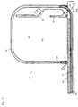
- FIG. 1 shows in cross section the device 10 according to the invention with the plate 50 serving as a working and storage surface and one of the plates arranged thereon Side parts 60.
- the side part 60 has a guide element 40 which adjoins three Sides of the side part 60 extends.
- the plate 50 has a space 502 in which a guide element 52 is arranged, which is a straight and a curved Section.
- the curved section of the guide element 52 projects through an opening 504 of the plate 50 out of this and is advantageously detachable with the Guide element 40 of the side part 60 can be connected.
- the closure-side end region 24 of the closure element 20 is closed Condition of the device 10 on the plate 50. It is also possible that the plate 50 and the closure-side end region 24 are not immediate, but communicate with each other by means of a strip or cover. Will that Closure element 20 moved from the position shown in Fig. 1 is carried out first a vertical displacement of the end portion 24 of the closure element 20 to the curved and then the horizontal area of the guide element 40 of the side part 60 is reached. During the displacement of the closure element 20 is the one not shown in FIG. 1 from the closure side End region 24 spaced second end region of the closure element accordingly on the back of the side part 60 or already included in the plate 50.
- the guide elements 40, 52 are such in Direction of movement of the closure element arranged that the closure element 20 at least partially on the side of the device formed by the plate 50 10 is receivable, the in the closed position shown in Fig. 1 Device 10 to the end portion 24 of the closure element on the closure side 20 adjacent.
- the closure element 20 is largely displaced in the guide elements 40 and 52 possible without winding up an axis is necessary.
- the space 30, which in the closed state the device 10 through the side parts 60 and through the closure element 20th and the plate 50 is limited, easily accessible.
- sockets 140 which are preferably with a line with each other and with a power supply device are connectable. There is a room just below socket 140 which can be delimited by the wall 150 and which is used to hold the cables Serves electrical appliances.
- a first extension 110 is located in the guide element 52 of the plate 50, the corresponding movement of the closure element of this or of a second extension piece arranged thereon is movable.
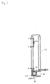
- Fig. 2 shows in longitudinal section the guide element 52, which in the plate or in the Cavity of the plate is mountable.
- the guide element 52 has a straight one and a curved section. It is designed as a rail in which the as Spring designed tension element 100 is receivable.
- the bolt 130 In one end of the spring there is the bolt 130, which in corresponding walls of the guide element 52 is arranged.
- the bolt 130 represents an end point of the tension element 100, while at the other end region the first extension piece 110 is arranged.
- the extension piece 110 is in a second groove 90, which with the first groove 80 into which the edge regions of the closure element can be received are connected.
- the edge area of the closure element accommodated in the groove 80 comes with a corresponding displacement of the closure element from a predeterminable position with that arranged on the extension piece 110 Projection 120 in contact and stretches the tension element from this position 100.
- it ensures that a closing of the closure element is facilitated in that the tension element in the corresponding tensioned state on the closure element one in the direction of movement exerts effective force.
- Those indicated in Fig. 3 along lines B-B and C-C Sectional drawings of the extension 110 and the spring end with bolt 130 are enlarged in Fig. 2 at the corresponding locations of the guide element 52 shown.
Landscapes
- Engineering & Computer Science (AREA)
- Structural Engineering (AREA)
- Architecture (AREA)
- Civil Engineering (AREA)
- Operating, Guiding And Securing Of Roll- Type Closing Members (AREA)
- External Artificial Organs (AREA)
- Lock And Its Accessories (AREA)
- Power-Operated Mechanisms For Wings (AREA)
- Casings For Electric Apparatus (AREA)
- Telephone Set Structure (AREA)
Applications Claiming Priority (2)
| Application Number | Priority Date | Filing Date | Title |
|---|---|---|---|
| DE19738933A DE19738933C1 (de) | 1997-09-05 | 1997-09-05 | Verschließbare Vorrichtung zur Geräteaufnahme |
| DE19738933 | 1997-09-05 |
Publications (3)
| Publication Number | Publication Date |
|---|---|
| EP0900908A2 true EP0900908A2 (fr) | 1999-03-10 |
| EP0900908A3 EP0900908A3 (fr) | 2000-12-06 |
| EP0900908B1 EP0900908B1 (fr) | 2004-09-29 |
Family
ID=7841355
Family Applications (1)
| Application Number | Title | Priority Date | Filing Date |
|---|---|---|---|
| EP98113427A Expired - Lifetime EP0900908B1 (fr) | 1997-09-05 | 1998-07-17 | Dispositif à fermeture pour la réception d'appareils |
Country Status (4)
| Country | Link |
|---|---|
| EP (1) | EP0900908B1 (fr) |
| AT (1) | ATE278095T1 (fr) |
| DE (2) | DE19738933C1 (fr) |
| ES (1) | ES2229426T3 (fr) |
Cited By (1)
| Publication number | Priority date | Publication date | Assignee | Title |
|---|---|---|---|---|
| US12196531B2 (en) | 2020-07-17 | 2025-01-14 | ProtectEd Solutions LLC | Protective cabinet |
Family Cites Families (6)
| Publication number | Priority date | Publication date | Assignee | Title |
|---|---|---|---|---|
| DE176753C (fr) * | ||||
| CH150999A (fr) * | 1930-11-28 | 1931-11-30 | Jahnle Firmin Antoine | Récipient à dispositif de fermeture à rideau et procédé pour sa fabrication. |
| US3351405A (en) * | 1966-04-25 | 1967-11-07 | Hirsh Mfg Co Sa | Desk top |
| DE2161391A1 (de) * | 1971-12-10 | 1973-06-14 | Toshihiko Sakow | Tisch mit in sich geschlossenen unabhaengigen deckel |
| US4108517A (en) * | 1977-05-24 | 1978-08-22 | Roth American, Inc. | Child's desk with slide-door and guideway therefor |
| DE3536948A1 (de) * | 1985-10-17 | 1987-04-23 | Pfaff Haushaltmasch | Naehschrank |
-
1997
- 1997-09-05 DE DE19738933A patent/DE19738933C1/de not_active Expired - Fee Related
-
1998
- 1998-07-17 ES ES98113427T patent/ES2229426T3/es not_active Expired - Lifetime
- 1998-07-17 AT AT98113427T patent/ATE278095T1/de not_active IP Right Cessation
- 1998-07-17 DE DE59812018T patent/DE59812018D1/de not_active Expired - Fee Related
- 1998-07-17 EP EP98113427A patent/EP0900908B1/fr not_active Expired - Lifetime
Cited By (1)
| Publication number | Priority date | Publication date | Assignee | Title |
|---|---|---|---|---|
| US12196531B2 (en) | 2020-07-17 | 2025-01-14 | ProtectEd Solutions LLC | Protective cabinet |
Also Published As
| Publication number | Publication date |
|---|---|
| EP0900908B1 (fr) | 2004-09-29 |
| ES2229426T3 (es) | 2005-04-16 |
| EP0900908A3 (fr) | 2000-12-06 |
| DE19738933C1 (de) | 1998-10-29 |
| DE59812018D1 (de) | 2004-11-04 |
| ATE278095T1 (de) | 2004-10-15 |
Similar Documents
| Publication | Publication Date | Title |
|---|---|---|
| EP3622149B1 (fr) | Rail de guidage d'un chariot d'une porte de meuble | |
| EP4077844A1 (fr) | Dispositif pour guider une porte coulissante ou une porte accordéon | |
| DE69002837T2 (de) | Vorrichtung mit zwei sich auseinanderbewegenden Läden. | |
| DE10117173A9 (de) | Tuer | |
| EP0900908B1 (fr) | Dispositif à fermeture pour la réception d'appareils | |
| DE1555632C3 (fr) | ||
| AT401405B (de) | Rolladen | |
| DE10304899B4 (de) | Rollladen | |
| DE2928118C2 (de) | Zur nebeneinander gereihten Befestigung an einer Montageschiene ausgebildetes Schalttafelelement, insbesondere Sicherungsautomat oder Trennschalter | |
| EP3483374B1 (fr) | Rail de guidage permettant le guidage d'un battant de porte entre une position d'ouverture et une position de fermeture | |
| DE102004005781A1 (de) | Jalousieeinheit | |
| DE2643698C2 (de) | Einrichtungsschrank, insbesondere für die Lagerung von Werkzeug in einer Werkstatt, Garage und dgl. | |
| EP4474610B1 (fr) | Dispositif de protection pour une ouverture de bâtiment et ouverture de bâtiment dotée d'un tel dispositif de protection | |
| DE10304898B4 (de) | Rollladen | |
| DE4403870A1 (de) | Sicherheitstür | |
| DE3215943C2 (de) | Führungsschiene für Vertikal-Jalousien | |
| EP4474611A1 (fr) | Ouverture de bâtiment dotée d'un dispositif de protection | |
| AT396001B (de) | Abschlussprofil fuer eine seitlich gefuehrte rolltuer od.dgl. | |
| DE4420537A1 (de) | Personalcomputer mit einem Gehäuse und in diesem Gehäuse angeordneten elektronischen Baueinheiten | |
| DE69301583T2 (de) | Schiebetritt eines Nutzfahrzeuges mit Verriegelungseinrichtung | |
| DE10304896B4 (de) | Vorrichtung zum Verschließen von Gebäudeöffnungen | |
| WO2022008494A1 (fr) | Panneau chauffant à ir | |
| DE29509556U1 (de) | Schaltschrank mit Montageplatte | |
| CH683816A5 (de) | Bediengehäuse. | |
| DE9309674U1 (de) | Sicherheits-schaltertheke |
Legal Events
| Date | Code | Title | Description |
|---|---|---|---|
| PUAI | Public reference made under article 153(3) epc to a published international application that has entered the european phase |
Free format text: ORIGINAL CODE: 0009012 |
|
| AK | Designated contracting states |
Kind code of ref document: A2 Designated state(s): AT BE CH DE ES FR GB IT LI LU NL |
|
| AX | Request for extension of the european patent |
Free format text: AL;LT;LV;MK;RO;SI |
|
| PUAL | Search report despatched |
Free format text: ORIGINAL CODE: 0009013 |
|
| AK | Designated contracting states |
Kind code of ref document: A3 Designated state(s): AT BE CH CY DE DK ES FI FR GB GR IE IT LI LU MC NL PT SE |
|
| AX | Request for extension of the european patent |
Free format text: AL;LT;LV;MK;RO;SI |
|
| RIC1 | Information provided on ipc code assigned before grant |
Free format text: 7E 06B 9/00 A, 7E 06B 9/11 B |
|
| 17P | Request for examination filed |
Effective date: 20010322 |
|
| AKX | Designation fees paid |
Free format text: AT BE CH DE ES FR GB IT LI LU NL |
|
| 17Q | First examination report despatched |
Effective date: 20030807 |
|
| GRAP | Despatch of communication of intention to grant a patent |
Free format text: ORIGINAL CODE: EPIDOSNIGR1 |
|
| GRAS | Grant fee paid |
Free format text: ORIGINAL CODE: EPIDOSNIGR3 |
|
| GRAA | (expected) grant |
Free format text: ORIGINAL CODE: 0009210 |
|
| RAP1 | Party data changed (applicant data changed or rights of an application transferred) |
Owner name: BULTHAUP GMBH & CO. KG |
|
| AK | Designated contracting states |
Kind code of ref document: B1 Designated state(s): AT BE CH DE ES FR GB IT LI LU NL |
|
| PG25 | Lapsed in a contracting state [announced via postgrant information from national office to epo] |
Ref country code: NL Free format text: LAPSE BECAUSE OF FAILURE TO SUBMIT A TRANSLATION OF THE DESCRIPTION OR TO PAY THE FEE WITHIN THE PRESCRIBED TIME-LIMIT Effective date: 20040929 Ref country code: GB Free format text: LAPSE BECAUSE OF FAILURE TO SUBMIT A TRANSLATION OF THE DESCRIPTION OR TO PAY THE FEE WITHIN THE PRESCRIBED TIME-LIMIT Effective date: 20040929 |
|
| REG | Reference to a national code |
Ref country code: GB Ref legal event code: FG4D Free format text: NOT ENGLISH |
|
| REG | Reference to a national code |
Ref country code: CH Ref legal event code: EP |
|
| REF | Corresponds to: |
Ref document number: 59812018 Country of ref document: DE Date of ref document: 20041104 Kind code of ref document: P |
|
| NLV1 | Nl: lapsed or annulled due to failure to fulfill the requirements of art. 29p and 29m of the patents act | ||
| REG | Reference to a national code |
Ref country code: ES Ref legal event code: FG2A Ref document number: 2229426 Country of ref document: ES Kind code of ref document: T3 |
|
| GBV | Gb: ep patent (uk) treated as always having been void in accordance with gb section 77(7)/1977 [no translation filed] |
Effective date: 20040929 |
|
| PG25 | Lapsed in a contracting state [announced via postgrant information from national office to epo] |
Ref country code: LU Free format text: LAPSE BECAUSE OF NON-PAYMENT OF DUE FEES Effective date: 20050717 |
|
| PG25 | Lapsed in a contracting state [announced via postgrant information from national office to epo] |
Ref country code: ES Free format text: LAPSE BECAUSE OF NON-PAYMENT OF DUE FEES Effective date: 20050718 |
|
| PG25 | Lapsed in a contracting state [announced via postgrant information from national office to epo] |
Ref country code: LI Free format text: LAPSE BECAUSE OF NON-PAYMENT OF DUE FEES Effective date: 20050731 Ref country code: CH Free format text: LAPSE BECAUSE OF NON-PAYMENT OF DUE FEES Effective date: 20050731 Ref country code: BE Free format text: LAPSE BECAUSE OF NON-PAYMENT OF DUE FEES Effective date: 20050731 |
|
| PLBE | No opposition filed within time limit |
Free format text: ORIGINAL CODE: 0009261 |
|
| STAA | Information on the status of an ep patent application or granted ep patent |
Free format text: STATUS: NO OPPOSITION FILED WITHIN TIME LIMIT |
|
| ET | Fr: translation filed | ||
| 26N | No opposition filed |
Effective date: 20050630 |
|
| REG | Reference to a national code |
Ref country code: CH Ref legal event code: PL |
|
| PG25 | Lapsed in a contracting state [announced via postgrant information from national office to epo] |
Ref country code: FR Free format text: LAPSE BECAUSE OF NON-PAYMENT OF DUE FEES Effective date: 20060331 |
|
| REG | Reference to a national code |
Ref country code: FR Ref legal event code: ST Effective date: 20060331 |
|
| REG | Reference to a national code |
Ref country code: ES Ref legal event code: FD2A Effective date: 20050718 |
|
| BERE | Be: lapsed |
Owner name: *BULTHAUP G.M.B.H. & CO. K.G. Effective date: 20050731 |
|
| PGFP | Annual fee paid to national office [announced via postgrant information from national office to epo] |
Ref country code: DE Payment date: 20080730 Year of fee payment: 11 |
|
| PGFP | Annual fee paid to national office [announced via postgrant information from national office to epo] |
Ref country code: IT Payment date: 20080724 Year of fee payment: 11 Ref country code: AT Payment date: 20080725 Year of fee payment: 11 |
|
| PG25 | Lapsed in a contracting state [announced via postgrant information from national office to epo] |
Ref country code: DE Free format text: LAPSE BECAUSE OF NON-PAYMENT OF DUE FEES Effective date: 20100202 Ref country code: AT Free format text: LAPSE BECAUSE OF NON-PAYMENT OF DUE FEES Effective date: 20090717 |
|
| PG25 | Lapsed in a contracting state [announced via postgrant information from national office to epo] |
Ref country code: IT Free format text: LAPSE BECAUSE OF NON-PAYMENT OF DUE FEES Effective date: 20090717 |