EP0900932A1 - Système d'injection de combustible pour un moteur à combustion interne - Google Patents
Système d'injection de combustible pour un moteur à combustion interne Download PDFInfo
- Publication number
- EP0900932A1 EP0900932A1 EP98110449A EP98110449A EP0900932A1 EP 0900932 A1 EP0900932 A1 EP 0900932A1 EP 98110449 A EP98110449 A EP 98110449A EP 98110449 A EP98110449 A EP 98110449A EP 0900932 A1 EP0900932 A1 EP 0900932A1
- Authority
- EP
- European Patent Office
- Prior art keywords
- fuel
- pressure
- valve
- additional liquid
- pressure chamber
- Prior art date
- Legal status (The legal status is an assumption and is not a legal conclusion. Google has not performed a legal analysis and makes no representation as to the accuracy of the status listed.)
- Granted
Links
- 239000000446 fuel Substances 0.000 title claims abstract description 59
- 238000002347 injection Methods 0.000 title claims abstract description 33
- 239000007924 injection Substances 0.000 title claims abstract description 33
- 238000002485 combustion reaction Methods 0.000 title claims description 15
- 239000007788 liquid Substances 0.000 claims description 45
- 239000000126 substance Substances 0.000 claims description 5
- 239000012530 fluid Substances 0.000 abstract 3
- 230000009977 dual effect Effects 0.000 abstract 2
- 239000004020 conductor Substances 0.000 abstract 1
- MWUXSHHQAYIFBG-UHFFFAOYSA-N Nitric oxide Chemical compound O=[N] MWUXSHHQAYIFBG-UHFFFAOYSA-N 0.000 description 3
- 238000011144 upstream manufacturing Methods 0.000 description 3
- XLYOFNOQVPJJNP-UHFFFAOYSA-N water Substances O XLYOFNOQVPJJNP-UHFFFAOYSA-N 0.000 description 3
- 239000002828 fuel tank Substances 0.000 description 2
- 238000012423 maintenance Methods 0.000 description 2
- 230000000149 penetrating effect Effects 0.000 description 2
- 230000015572 biosynthetic process Effects 0.000 description 1
- 239000002283 diesel fuel Substances 0.000 description 1
- 230000000694 effects Effects 0.000 description 1
- 238000000034 method Methods 0.000 description 1
- 230000008092 positive effect Effects 0.000 description 1
- 239000004071 soot Substances 0.000 description 1
Images

Classifications
-
- F—MECHANICAL ENGINEERING; LIGHTING; HEATING; WEAPONS; BLASTING
- F02—COMBUSTION ENGINES; HOT-GAS OR COMBUSTION-PRODUCT ENGINE PLANTS
- F02M—SUPPLYING COMBUSTION ENGINES IN GENERAL WITH COMBUSTIBLE MIXTURES OR CONSTITUENTS THEREOF
- F02M63/00—Other fuel-injection apparatus having pertinent characteristics not provided for in groups F02M39/00 - F02M57/00 or F02M67/00; Details, component parts, or accessories of fuel-injection apparatus, not provided for in, or of interest apart from, the apparatus of groups F02M39/00 - F02M61/00 or F02M67/00; Combination of fuel pump with other devices, e.g. lubricating oil pump
- F02M63/0003—Fuel-injection apparatus having a cyclically-operated valve for connecting a pressure source, e.g. constant pressure pump or accumulator, to an injection valve held closed mechanically, e.g. by springs, and automatically opened by fuel pressure
- F02M63/0007—Fuel-injection apparatus having a cyclically-operated valve for connecting a pressure source, e.g. constant pressure pump or accumulator, to an injection valve held closed mechanically, e.g. by springs, and automatically opened by fuel pressure using electrically actuated valves
-
- F—MECHANICAL ENGINEERING; LIGHTING; HEATING; WEAPONS; BLASTING
- F02—COMBUSTION ENGINES; HOT-GAS OR COMBUSTION-PRODUCT ENGINE PLANTS
- F02M—SUPPLYING COMBUSTION ENGINES IN GENERAL WITH COMBUSTIBLE MIXTURES OR CONSTITUENTS THEREOF
- F02M43/00—Fuel-injection apparatus operating simultaneously on two or more fuels, or on a liquid fuel and another liquid, e.g. the other liquid being an anti-knock additive
- F02M43/04—Injectors peculiar thereto
-
- F—MECHANICAL ENGINEERING; LIGHTING; HEATING; WEAPONS; BLASTING
- F02—COMBUSTION ENGINES; HOT-GAS OR COMBUSTION-PRODUCT ENGINE PLANTS
- F02M—SUPPLYING COMBUSTION ENGINES IN GENERAL WITH COMBUSTIBLE MIXTURES OR CONSTITUENTS THEREOF
- F02M47/00—Fuel-injection apparatus operated cyclically with fuel-injection valves actuated by fluid pressure
- F02M47/02—Fuel-injection apparatus operated cyclically with fuel-injection valves actuated by fluid pressure of accumulator-injector type, i.e. having fuel pressure of accumulator tending to open, and fuel pressure in other chamber tending to close, injection valves and having means for periodically releasing that closing pressure
- F02M47/027—Electrically actuated valves draining the chamber to release the closing pressure
-
- F—MECHANICAL ENGINEERING; LIGHTING; HEATING; WEAPONS; BLASTING
- F02—COMBUSTION ENGINES; HOT-GAS OR COMBUSTION-PRODUCT ENGINE PLANTS
- F02M—SUPPLYING COMBUSTION ENGINES IN GENERAL WITH COMBUSTIBLE MIXTURES OR CONSTITUENTS THEREOF
- F02M63/00—Other fuel-injection apparatus having pertinent characteristics not provided for in groups F02M39/00 - F02M57/00 or F02M67/00; Details, component parts, or accessories of fuel-injection apparatus, not provided for in, or of interest apart from, the apparatus of groups F02M39/00 - F02M61/00 or F02M67/00; Combination of fuel pump with other devices, e.g. lubricating oil pump
- F02M63/0012—Valves
- F02M63/0031—Valves characterized by the type of valves, e.g. special valve member details, valve seat details, valve housing details
- F02M63/0047—Four-way valves or valves with more than four ways
-
- F—MECHANICAL ENGINEERING; LIGHTING; HEATING; WEAPONS; BLASTING
- F02—COMBUSTION ENGINES; HOT-GAS OR COMBUSTION-PRODUCT ENGINE PLANTS
- F02M—SUPPLYING COMBUSTION ENGINES IN GENERAL WITH COMBUSTIBLE MIXTURES OR CONSTITUENTS THEREOF
- F02M63/00—Other fuel-injection apparatus having pertinent characteristics not provided for in groups F02M39/00 - F02M57/00 or F02M67/00; Details, component parts, or accessories of fuel-injection apparatus, not provided for in, or of interest apart from, the apparatus of groups F02M39/00 - F02M61/00 or F02M67/00; Combination of fuel pump with other devices, e.g. lubricating oil pump
- F02M63/0012—Valves
- F02M63/0031—Valves characterized by the type of valves, e.g. special valve member details, valve seat details, valve housing details
- F02M63/0049—Combined valve units, e.g. for controlling pumping chamber and injection valve
Definitions
- the invention relates to a fuel injection system for Internal combustion engines according to the preamble of claim 1 out.
- a high-pressure feed pump fills the fuel injection system a high pressure accumulator with fuel from a storage tank. Pressure lines run from the high-pressure accumulator (common rail) to the individual injection nozzles of the internal combustion engine.
- Fuel diesel fuel
- An additional liquid the nitrogen oxide and soot emissions of the internal combustion engine lowered. This type of injection also affects a reduction in fuel consumption. Water is generally used as the additional liquid.
- the internal combustion engine must have a dynamic water content can be quickly reduced or switched off. Otherwise increased the HC emission.
- the high injection pressure is in the injector is permanently present. Therefore, in the known Fuel injection system provided for relief the storage of additional liquid in the pressure chamber Relieve pressure within the pressure chamber for a short time. This is done by a 3/2-way valve, so that fuel from the Pressure chamber pushed out by the penetrating additional liquid can be.
- the 3/2-way valve opens during the injection break the passage to a drain line for the Pressure reduction and return of the fuel from the injection nozzle in a storage container.
- the inflow closed by the commom rail pressure accumulator Parallel to this Valve control is provided by another check valve an opening for the feed of additional liquid (water) Approved.
- the additional liquid is in the area of the nozzle tip fed to the injector.
- the check valve is held in an open position until the desired one Amount of additional liquid upstream in the pressure chamber is.
- the admixture of fuel and additional liquid in the Print room requires precise and fast control of the Valve arrangement. For example, depending on the operating state the internal combustion engine the amount of fuel or additional liquid can be varied from work cycle to work cycle can.
- the Changeover valve for fuel storage is a 3/2-way valve trained while additionally a separate check valve for the storage of additional liquid in the Pressure room becomes necessary.
- This fuel injection system has only one Switch valve to switch between the liquid lines for fuel and additional liquid or for pressure relief of the pressure chamber to be able to switch.
- a single valve as a control valve can be rapid changes in the storage of fuel or additional liquid lead into the pressure room. Through the control a single valve can be the valve assembly be switched more precisely and faster.
- a 2/2 solenoid valve can be used.
- a 2/2-way valve either the two pressure relief openings Pressure chamber or the opening to the common rail high-pressure accumulator be released.
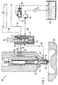
- the exemplary embodiment of a fuel injection system with an injector 10 according to FIG. 1 is in a state in which additional liquid is stored in a pressure chamber 11 of a two-component injection nozzle 12.
- a changeover valve 16 with a Valve housings 17 Due to the position of a changeover valve 16 with a Valve housings 17 are the pressure chamber 11 and a feed line 18 for fuel of the two-component injector 12 largely relieved of pressure.
- the feed line 18 is via a return line 19 connected to a fuel tank.
- a decoupling throttle 20 is installed.
- the changeover valve 16 has a first valve opening 21 and a second valve opening 22.
- the first valve opening 21 connects the feed line 18 to the fuel tank.
- the second valve opening 22 allows additional liquid from an auxiliary liquid container 23 with the help a feed pump 24 in the pressure chamber 11 of the two-substance injector 12 to be stored.
- a connecting line 25 is switched continuously with an additional liquid line 26.
- a fuel supply line 27, however, is from the fuel line 28 separated.
- the fuel line 28 can fuel from a common rail pressure accumulator 29 forward.
- Pressure regulator 30 and filter 31 ensure one controlled and defined supply of additional liquid from the additional liquid container 23.
- the fuel injection system with an injector 10 is in a state in which fuel and stored additional liquid are injected from the two-substance injection nozzle 12 from the pressure chamber 11 into a combustion chamber of the internal combustion engine 32.
- the internal combustion engine 32 is again only in FIG indicated and shown with their edge area.
- the position of the changeover valve 16 gives the first Valve opening 21 gives access to the common rail pressure accumulator 29 free.
- the return line 19 is through the valve position of the changeover valve 16 separated from the supply line 18.
- the additional liquid line 25 also has none Passage to makeup liquid line 26. Hence, no additional liquid from the additional liquid container 23 get into the pressure chamber 11.
Landscapes
- Engineering & Computer Science (AREA)
- Chemical & Material Sciences (AREA)
- Combustion & Propulsion (AREA)
- Mechanical Engineering (AREA)
- General Engineering & Computer Science (AREA)
- Physics & Mathematics (AREA)
- Fluid Mechanics (AREA)
- Fuel-Injection Apparatus (AREA)
- Output Control And Ontrol Of Special Type Engine (AREA)
Applications Claiming Priority (2)
| Application Number | Priority Date | Filing Date | Title |
|---|---|---|---|
| DE19738397A DE19738397A1 (de) | 1997-09-03 | 1997-09-03 | Kraftstoffeinspritzanlage für eine Brennkraftmaschine |
| DE19738397 | 1997-09-03 |
Publications (2)
| Publication Number | Publication Date |
|---|---|
| EP0900932A1 true EP0900932A1 (fr) | 1999-03-10 |
| EP0900932B1 EP0900932B1 (fr) | 2002-09-11 |
Family
ID=7841004
Family Applications (1)
| Application Number | Title | Priority Date | Filing Date |
|---|---|---|---|
| EP98110449A Expired - Lifetime EP0900932B1 (fr) | 1997-09-03 | 1998-06-08 | Système d'injection de combustible pour un moteur à combustion interne |
Country Status (4)
| Country | Link |
|---|---|
| US (1) | US5979410A (fr) |
| EP (1) | EP0900932B1 (fr) |
| JP (1) | JPH11148436A (fr) |
| DE (2) | DE19738397A1 (fr) |
Cited By (2)
| Publication number | Priority date | Publication date | Assignee | Title |
|---|---|---|---|---|
| CN102084117A (zh) * | 2008-06-19 | 2011-06-01 | 西港能源有限公司 | 双燃料连接器 |
| EP3483420A1 (fr) * | 2017-11-13 | 2019-05-15 | Winterthur Gas & Diesel AG | Buse d'injection de carburant et procédé d'injection de carburant pour un gros moteur diesel ainsi que gros moteur diesel |
Families Citing this family (29)
| Publication number | Priority date | Publication date | Assignee | Title |
|---|---|---|---|---|
| DE19742073A1 (de) * | 1997-09-24 | 1999-03-25 | Bosch Gmbh Robert | Kraftstoffeinspritzvorrichtung für Brennkraftmaschinen |
| DE19742320A1 (de) * | 1997-09-25 | 1999-04-01 | Bosch Gmbh Robert | Kraftstoffeinspritzventil |
| DE19746490A1 (de) * | 1997-10-22 | 1999-04-29 | Bosch Gmbh Robert | Kraftstoffeinspritzanlage für eine Brennkraftmaschine |
| DE19746492A1 (de) * | 1997-10-22 | 1999-04-29 | Bosch Gmbh Robert | Kraftstoffeinspritzanlage für eine Brennkraftmaschine |
| DE19746489A1 (de) * | 1997-10-22 | 1999-04-29 | Bosch Gmbh Robert | Kraftstoffeinspritzanlage für eine Brennkraftmaschine |
| DE19816316A1 (de) * | 1998-04-11 | 1999-10-14 | Bosch Gmbh Robert | Kraftstoffeinspritzvorrichtung für Brennkraftmaschinen |
| DE19939426A1 (de) * | 1999-08-20 | 2001-03-01 | Bosch Gmbh Robert | Kraftstoffeinspritzsystem für eine Brennkraftmaschine |
| DE19939422A1 (de) * | 1999-08-20 | 2001-03-01 | Bosch Gmbh Robert | Kraftstoffeinspritzsystem für eine Brennkraftmaschine |
| EP1081372B1 (fr) * | 1999-08-31 | 2004-10-13 | Denso Corporation | Dispositif d'injection de carburant |
| DE19954057A1 (de) * | 1999-11-10 | 2001-06-07 | Bosch Gmbh Robert | Steuerelement für die Steuerung von Einspritzsystemen |
| DE10015268A1 (de) * | 2000-03-28 | 2001-10-04 | Siemens Ag | Einspritzventil mit Bypaßdrossel |
| JP2002030937A (ja) * | 2000-04-28 | 2002-01-31 | Gureitochiren:Kk | エンジン及びシステム |
| DE10105031A1 (de) * | 2001-02-05 | 2002-08-14 | Bosch Gmbh Robert | Vorrichtung zur Dämpfung von Druckpulsationen in Hochdruckeinspritzsystemen |
| DE10113028A1 (de) * | 2001-03-17 | 2002-09-26 | Bosch Gmbh Robert | 3/2-Wegeventil |
| ITTO20010539A1 (it) * | 2001-06-05 | 2002-12-05 | Fiat Ricerche | Iniettore di combustibile per un motore a combustione interna. |
| DE10131640A1 (de) * | 2001-06-29 | 2003-01-16 | Bosch Gmbh Robert | Kraftstoffinjektor mit Einspritzverlaufsformung durch schaltbare Drosselelemente |
| DE10131953A1 (de) * | 2001-07-02 | 2003-01-23 | Siemens Ag | Steuermodul für einen Injektor eines Speichereinspritzsystems |
| DE10141111B4 (de) * | 2001-08-22 | 2005-10-13 | Robert Bosch Gmbh | Kraftstoffeinspritzvorrichtung für Brennkraftmaschinen |
| US6439202B1 (en) * | 2001-11-08 | 2002-08-27 | Cummins Inc. | Hybrid electronically controlled unit injector fuel system |
| RU2269670C2 (ru) * | 2002-09-20 | 2006-02-10 | Военный автомобильный институт | Система подачи топлива в дизель |
| RU2269662C2 (ru) * | 2002-09-20 | 2006-02-10 | Военный автомобильный институт | Система подачи топлива в дизель |
| JP2009167853A (ja) * | 2008-01-15 | 2009-07-30 | Denso Corp | 内燃機関の制御装置 |
| CA2633846C (fr) * | 2008-06-27 | 2009-12-29 | Westport Power Inc. | Soupape d'injection de carburant et methode de co-injection d'un liquide et d'un carburant gazeux dans la chambre de combustion d'un moteur a combustion interne |
| US10077748B2 (en) * | 2014-12-23 | 2018-09-18 | Cummins Inc. | Fuel injector for common rail |
| CN104806405B (zh) * | 2015-04-30 | 2017-04-12 | 哈尔滨工程大学 | 双作用常闭电控单体泵 |
| CN104806407B (zh) * | 2015-04-30 | 2017-04-12 | 哈尔滨工程大学 | 多模式电控单体泵 |
| CN104806404B (zh) * | 2015-04-30 | 2017-12-12 | 哈尔滨工程大学 | 双作用压电式常闭电控单体泵 |
| CN104806408B (zh) * | 2015-04-30 | 2017-05-24 | 哈尔滨工程大学 | 多模式常闭电控单体泵 |
| RU174438U1 (ru) * | 2016-10-18 | 2017-10-12 | Федеральное государственное казенное военное образовательное учреждение высшего образования "Рязанское высшее воздушно-десантное ордена Суворова дважды Краснознаменное командное училище имени генерала армии В.Ф. Маргелова" Министерства обороны Российской Федерации | Система топливоподачи дизеля |
Citations (3)
| Publication number | Priority date | Publication date | Assignee | Title |
|---|---|---|---|---|
| DE4341739C1 (de) * | 1993-12-08 | 1995-03-30 | Mtu Friedrichshafen Gmbh | Einspritzsystem |
| DE4337048A1 (de) * | 1993-10-29 | 1995-05-04 | Daimler Benz Ag | Kraftstoffeinspritzanlage für eine Brennkraftmaschine |
| US5651346A (en) * | 1994-12-22 | 1997-07-29 | Mtu Motoren- Und Turbinen-Union Friedrichshafen Gmbh | Accumulator-type injection system |
Family Cites Families (11)
| Publication number | Priority date | Publication date | Assignee | Title |
|---|---|---|---|---|
| US2984229A (en) * | 1956-12-05 | 1961-05-16 | Alco Products Inc | Multi-fuel supply system |
| US3807377A (en) * | 1971-06-14 | 1974-04-30 | Ethyl Corp | Fuel system |
| US3908794A (en) * | 1973-11-16 | 1975-09-30 | Richard L Stone | Detachable boat boarding device |
| US4505244A (en) * | 1982-05-06 | 1985-03-19 | Cummins Engine Company, Inc. | Fuel injection system |
| GB2126650B (en) * | 1982-08-31 | 1988-02-10 | George Stan Baranescu | I c engine injection system providing a stratified charge of two fuels |
| BR8801648A (pt) * | 1988-04-07 | 1989-11-07 | Bosch Do Brasil | Sistema de partida a frio para motores de combustao interna a alcool,processo de partida a frio e dispositivo a ser utilizado nos mesmos |
| US5194247A (en) * | 1989-08-24 | 1993-03-16 | Xina Nair | Synergistic skin depigmentation composition |
| DE4230641A1 (de) * | 1992-09-12 | 1994-03-17 | Bosch Gmbh Robert | Kraftstoff-Einspritzdüse mit Additiveinspritzung für Dieselmotoren |
| FI101168B (fi) * | 1994-12-23 | 1998-04-30 | Waertsilae Nsd Oy Ab | Ruiskutusjärjestely ja menetelmä sen käyttämiseksi polttomoottorissa |
| DE19535703C2 (de) * | 1995-09-26 | 1997-07-31 | Mtu Friedrichshafen Gmbh | Brennstoffeinspritzsystem |
| FI101739B1 (fi) * | 1996-08-16 | 1998-08-14 | Waertsila Nsd Oy Ab | Ruiskutusventtiilijärjestely |
-
1997
- 1997-09-03 DE DE19738397A patent/DE19738397A1/de not_active Withdrawn
-
1998
- 1998-06-08 DE DE59805489T patent/DE59805489D1/de not_active Expired - Fee Related
- 1998-06-08 EP EP98110449A patent/EP0900932B1/fr not_active Expired - Lifetime
- 1998-08-21 US US09/137,817 patent/US5979410A/en not_active Expired - Fee Related
- 1998-09-01 JP JP10247074A patent/JPH11148436A/ja active Pending
Patent Citations (4)
| Publication number | Priority date | Publication date | Assignee | Title |
|---|---|---|---|---|
| DE4337048A1 (de) * | 1993-10-29 | 1995-05-04 | Daimler Benz Ag | Kraftstoffeinspritzanlage für eine Brennkraftmaschine |
| DE4337048C2 (de) | 1993-10-29 | 1996-01-11 | Daimler Benz Ag | Kraftstoffeinspritzanlage für eine Brennkraftmaschine |
| DE4341739C1 (de) * | 1993-12-08 | 1995-03-30 | Mtu Friedrichshafen Gmbh | Einspritzsystem |
| US5651346A (en) * | 1994-12-22 | 1997-07-29 | Mtu Motoren- Und Turbinen-Union Friedrichshafen Gmbh | Accumulator-type injection system |
Cited By (2)
| Publication number | Priority date | Publication date | Assignee | Title |
|---|---|---|---|---|
| CN102084117A (zh) * | 2008-06-19 | 2011-06-01 | 西港能源有限公司 | 双燃料连接器 |
| EP3483420A1 (fr) * | 2017-11-13 | 2019-05-15 | Winterthur Gas & Diesel AG | Buse d'injection de carburant et procédé d'injection de carburant pour un gros moteur diesel ainsi que gros moteur diesel |
Also Published As
| Publication number | Publication date |
|---|---|
| EP0900932B1 (fr) | 2002-09-11 |
| JPH11148436A (ja) | 1999-06-02 |
| US5979410A (en) | 1999-11-09 |
| DE19738397A1 (de) | 1999-03-18 |
| DE59805489D1 (de) | 2002-10-17 |
Similar Documents
| Publication | Publication Date | Title |
|---|---|---|
| EP0900932B1 (fr) | Système d'injection de combustible pour un moteur à combustion interne | |
| EP1125049B1 (fr) | Procede et systeme d'injection de carburant combinee par levee/pression pour moteur a combustion interne | |
| EP1125046B1 (fr) | System d'injection de carburant pour un moteur à combustion interne avec un multiplicateur de pression | |
| DE3112381C2 (fr) | ||
| DE2558699C2 (de) | Pumpedüse für die Kraftstoffeinspritzung in eine Brennkraftmaschine | |
| EP1125058B1 (fr) | Systeme d'injection de carburant pour moteur a combustion interne | |
| DE69124228T2 (de) | Elektronische Hochdruckeinspritzkraftstoffleitung für Dieselmotoren | |
| DE102013012337A1 (de) | Brennstoffeinspritzvorrichtunq mit doppeltem Rückschlagelement und diese einsetzendes Brennstoffsystem | |
| DE4313852A1 (de) | Kraftstoffeinspritzeinrichtung für Brennkraftmaschinen | |
| DE4445586A1 (de) | Verfahren zur Reduzierung des Kraftstoffdruckes in einer Kraftstoffeinspritzeinrichtung | |
| DE102014005741A1 (de) | Dual-brennstoffeinspritzvorrichtung mit f-, a- und z-zumessöffnungssteuerung | |
| DE4445980C2 (de) | Einspritzsystem | |
| DE112011101053T5 (de) | Verdichtungsgezündeter Motor mit Brennstoffmischungseinspritzung | |
| EP1125045B1 (fr) | Systeme d'injection de carburant pour un moteur a combustion interne | |
| EP0760425A1 (fr) | Dispositif d'injection | |
| DE2750042A1 (de) | Kraftstoffeinspritzsystem | |
| DE112020001838T5 (de) | Kraftstoffsystem mit durchflussregelventil mit fester geometrie zur begrenzung des übersprechens des injektoren | |
| EP1121527B1 (fr) | Dispositif d'injection de carburant | |
| DE4341739C1 (de) | Einspritzsystem | |
| DE19512270A1 (de) | Kraftstoffeinspritzanlage für Brennkraftmaschine | |
| EP3483420B1 (fr) | Buse d'injection de carburant et procédé d'injection de carburant pour un gros moteur diesel ainsi que gros moteur diesel | |
| EP1354133B1 (fr) | Dispositif d'injection de carburant | |
| EP0704619A1 (fr) | Dispositif d'injection de combustible pour un moteur à combustion interne multicylindre | |
| EP0670424B1 (fr) | Système d'injection pour injecter un combustible et un liquide additionnel dans les chambres de combustion d'un moteur à combustion interne | |
| DE19923421C2 (de) | Injektor |
Legal Events
| Date | Code | Title | Description |
|---|---|---|---|
| PUAI | Public reference made under article 153(3) epc to a published international application that has entered the european phase |
Free format text: ORIGINAL CODE: 0009012 |
|
| AK | Designated contracting states |
Kind code of ref document: A1 Designated state(s): CH DE FR GB IT LI SE |
|
| AX | Request for extension of the european patent |
Free format text: AL;LT;LV;MK;RO;SI |
|
| 17P | Request for examination filed |
Effective date: 19990910 |
|
| AKX | Designation fees paid |
Free format text: CH DE FR GB IT LI SE |
|
| 17Q | First examination report despatched |
Effective date: 20010212 |
|
| GRAG | Despatch of communication of intention to grant |
Free format text: ORIGINAL CODE: EPIDOS AGRA |
|
| GRAG | Despatch of communication of intention to grant |
Free format text: ORIGINAL CODE: EPIDOS AGRA |
|
| GRAH | Despatch of communication of intention to grant a patent |
Free format text: ORIGINAL CODE: EPIDOS IGRA |
|
| GRAH | Despatch of communication of intention to grant a patent |
Free format text: ORIGINAL CODE: EPIDOS IGRA |
|
| GRAA | (expected) grant |
Free format text: ORIGINAL CODE: 0009210 |
|
| AK | Designated contracting states |
Kind code of ref document: B1 Designated state(s): CH DE FR GB IT LI SE |
|
| REG | Reference to a national code |
Ref country code: GB Ref legal event code: FG4D Free format text: NOT ENGLISH |
|
| REG | Reference to a national code |
Ref country code: CH Ref legal event code: EP |
|
| REG | Reference to a national code |
Ref country code: CH Ref legal event code: NV Representative=s name: SCINTILLA AG, DIREKTION |
|
| REF | Corresponds to: |
Ref document number: 59805489 Country of ref document: DE Date of ref document: 20021017 |
|
| GBT | Gb: translation of ep patent filed (gb section 77(6)(a)/1977) |
Effective date: 20021203 |
|
| ET | Fr: translation filed | ||
| PG25 | Lapsed in a contracting state [announced via postgrant information from national office to epo] |
Ref country code: GB Free format text: LAPSE BECAUSE OF NON-PAYMENT OF DUE FEES Effective date: 20030608 |
|
| PG25 | Lapsed in a contracting state [announced via postgrant information from national office to epo] |
Ref country code: SE Free format text: LAPSE BECAUSE OF NON-PAYMENT OF DUE FEES Effective date: 20030609 |
|
| PG25 | Lapsed in a contracting state [announced via postgrant information from national office to epo] |
Ref country code: LI Free format text: LAPSE BECAUSE OF NON-PAYMENT OF DUE FEES Effective date: 20030630 Ref country code: CH Free format text: LAPSE BECAUSE OF NON-PAYMENT OF DUE FEES Effective date: 20030630 |
|
| PLBE | No opposition filed within time limit |
Free format text: ORIGINAL CODE: 0009261 |
|
| STAA | Information on the status of an ep patent application or granted ep patent |
Free format text: STATUS: NO OPPOSITION FILED WITHIN TIME LIMIT |
|
| 26N | No opposition filed |
Effective date: 20030612 |
|
| GBPC | Gb: european patent ceased through non-payment of renewal fee |
Effective date: 20030608 |
|
| EUG | Se: european patent has lapsed | ||
| REG | Reference to a national code |
Ref country code: CH Ref legal event code: PL |
|
| PG25 | Lapsed in a contracting state [announced via postgrant information from national office to epo] |
Ref country code: FR Free format text: LAPSE BECAUSE OF NON-PAYMENT OF DUE FEES Effective date: 20040227 |
|
| REG | Reference to a national code |
Ref country code: FR Ref legal event code: ST |
|
| PG25 | Lapsed in a contracting state [announced via postgrant information from national office to epo] |
Ref country code: IT Free format text: LAPSE BECAUSE OF NON-PAYMENT OF DUE FEES Effective date: 20050608 |
|
| PGFP | Annual fee paid to national office [announced via postgrant information from national office to epo] |
Ref country code: DE Payment date: 20070828 Year of fee payment: 10 |
|
| PG25 | Lapsed in a contracting state [announced via postgrant information from national office to epo] |
Ref country code: DE Free format text: LAPSE BECAUSE OF NON-PAYMENT OF DUE FEES Effective date: 20090101 |