EP0900974A2 - Support de lampe dans une ouverture de réflecteur de phare - Google Patents
Support de lampe dans une ouverture de réflecteur de phare Download PDFInfo
- Publication number
- EP0900974A2 EP0900974A2 EP98116701A EP98116701A EP0900974A2 EP 0900974 A2 EP0900974 A2 EP 0900974A2 EP 98116701 A EP98116701 A EP 98116701A EP 98116701 A EP98116701 A EP 98116701A EP 0900974 A2 EP0900974 A2 EP 0900974A2
- Authority
- EP
- European Patent Office
- Prior art keywords
- reflector
- retaining ring
- elements
- collar
- side wall
- Prior art date
- Legal status (The legal status is an assumption and is not a legal conclusion. Google has not performed a legal analysis and makes no representation as to the accuracy of the status listed.)
- Withdrawn
Links
- 239000002184 metal Substances 0.000 claims description 6
- 230000001154 acute effect Effects 0.000 claims description 4
- 210000002105 tongue Anatomy 0.000 description 7
- 210000000078 claw Anatomy 0.000 description 4
- 230000002093 peripheral effect Effects 0.000 description 2
- 238000003780 insertion Methods 0.000 description 1
- 230000037431 insertion Effects 0.000 description 1
- 238000009434 installation Methods 0.000 description 1
- 238000000034 method Methods 0.000 description 1
- 230000008719 thickening Effects 0.000 description 1
Images
Classifications
-
- F—MECHANICAL ENGINEERING; LIGHTING; HEATING; WEAPONS; BLASTING
- F21—LIGHTING
- F21S—NON-PORTABLE LIGHTING DEVICES; SYSTEMS THEREOF; VEHICLE LIGHTING DEVICES SPECIALLY ADAPTED FOR VEHICLE EXTERIORS
- F21S41/00—Illuminating devices specially adapted for vehicle exteriors, e.g. headlamps
- F21S41/10—Illuminating devices specially adapted for vehicle exteriors, e.g. headlamps characterised by the light source
- F21S41/19—Attachment of light sources or lamp holders
- F21S41/196—Wire spring attachments
Definitions
- the invention relates to a holder of a lamp in an opening of a Reflector of a vehicle headlight with the opening of the reflector surrounding collar, with a retaining ring placed on the collar, which with barb-like ones pointing in the opposite direction Spreading elements is fixed on one side surface of the collar and to one counter to the mounting direction of the reflector runs adjacent.
- Such a holder of a lamp in an opening of a reflector Vehicle headlights are known from EP 0468 704 B1.
- the reflector is made of plastic and has an opening on the back surrounding molded collar.
- On the collar is a springy Sheet metal retaining ring placed on.
- the retaining ring has one across it Installation direction extending side wall, which to one of the end face of the collar formed adjacent surface runs adjacent.
- the side wall has on the outside a peripheral edge section pointing in the mounting direction. Fixing elements pointing in the direction of attachment protrude from the side wall, which inside the collar in corresponding recesses of the reflector intervene to the retaining ring in a certain rotational position to the reflector hold.
- Retaining springs are attached to the side wall, which hold the lamp with press their base against the reflector. From the inside of the wraparound Edge section of the retaining ring protrude barb-like expansion elements, which point against the mounting direction of the retaining ring and in the Claw the outer surface of the collar. It is disadvantageous that the Spreading elements after placing the retaining ring up against the of the End face of the collar formed stop surface more or less far can spring back, and the exact predetermined by the stop surface Position of the retaining ring is to the opening of the reflector receiving the lamp no longer exist. This ensures a secure mounting of the lamp with the Retaining springs of the retaining ring are no longer guaranteed. Besides, that can Fixing element of the retaining ring, which is in a recess in the reflector engages, disengage, and the ring is in an undesired position rotatable.
- DE 34 32 445 C2 is a holder for a lamp Vehicle headlights have become known, in which two from spring plate manufactured holding elements on opposite sides of a lamp receiving opening of the reflector are clamped. To the Holding elements are supported by a U-shaped retaining spring, which holds the lamp presses against the peripheral edge of the opening of the reflector. The assembly the two holding elements made of spring sheet metal are cumbersome and time consuming.
- the object of the invention is that described in the preamble of claim 1 Holding a lamp in an opening of a reflector To design vehicle headlights so that the retaining ring according to his Assembly, even if the spreader stars a little after putting on the retaining ring spring back, remains on the stop surface or near the stop surface runs to a precise position of the retaining ring to the lamp receiving Obtain opening of the reflector.
- This object is achieved according to the invention solved in that the stop surface by at least two Stop elements of the reflector is determined, between which at least a barb-like expansion element is arranged, which consists of a inner edge section of a side wall running transversely to the mounting direction a retaining ring made of sheet metal is cut free.
- the outside dimensions of the retaining ring can vary be when the stop elements outside the collar to the back of the reflector are formed and the retaining ring surrounds the collar on the outside.
- Stop elements are ribs formed on the back of the reflector usable, which with its wide side surface transversely to the neighboring The outer surface of the collar run. Such ribs are easy to demold and have no thickening towards the reflector, through which sink marks the reflection surface of the reflector can arise.
- the retaining ring is very securely attached to the collar of the reflector when it is by internal tension forces, which between the expansion elements and the stop elements exist, abutting the stop elements is held.
- the size of the internal tension forces depends on the Pressure forces of a mounting device with which the retaining ring between the Stop elements is pushed towards the reflector.
- the retaining ring has a high torsional stiffness when the Spreading elements on the base of a clearance in the side wall on the retaining ring are connected and the side wall from the outside to a Main extension of the side wall extending edge section is surrounded. Of the Edge section can in or against the mounting direction of the retaining ring be directed.
- the retaining ring can be manufactured inexpensively using the deep-drawing process, and the side surface of the side wall pointing counter to the mounting direction can serve as a contact surface for the mounting device.
- the force of the expansion elements with which the expansion elements in the Claw surface of the collar is large enough to secure To achieve tightness of the retaining ring on the collar when the expansion elements run at an acute angle to the surface in which the side wall of the Retaining ring lies.
- the expansion elements of the retaining ring claw very deep into the lateral surface of the Collar when it runs through her on the edge facing the collar Have free cutting existing degrees.
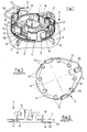
- a headlight for vehicles has a plastic one bowl-shaped reflector (2), which in its apex area for Receiving a lamp (1) has an opening.
- the lamp (1) is from the Back of the reflector (2) inserted into its opening and lies with one Base flange (18) on an outer edge region of the opening of the reflector (2).
- the collar (3) borders with its inner side surface on the outer edge of the base flange (18) of the lamp (1) and thus serves as a threading aid for the lamp (1) their insertion into the opening of the reflector (2).
- rib-like stop elements (8) on the back of the reflector (3) integrally formed, which with its wide side surfaces radially to the longitudinal axis of the Lamp (1) run.
- the stop elements (8) point to the back of the Reflector (2) pointing side each have a stop surface (7) for one Retaining ring (4).
- the stop surfaces (7) lie in an area to which the Longitudinal axis of the lamp (1) runs perpendicular.
- the rib-like stop elements (8) have a wall thickness which is not greater than the wall thickness of the cup-shaped reflector (2).
- the retaining ring (4) which is made of resilient, rests on the stop surfaces (7) Sheet is punched out.
- the retaining ring (4) is placed on the collar until he with a side wall (4) on the stop surfaces (7) of the stop elements (8) is present.
- the side wall (9) is at its outer edge from one against the Setting direction (5) of the retaining ring (4) directed edge section (10).
- the side wall (9) has clearances (15) on its inner edge the base of which is designed as tongues of barb-like expansion elements (6) are connected.
- the spreading elements (6) point counter to the direction of attachment (5) and run at an acute angle ⁇ to the surface in which the Contact surfaces (7).
- the angle ⁇ is in the relaxed state of the expansion elements (6) preferably between 20 ° and 50 °.
- the tongue-like expansion elements (6) are cut free in the mounting direction (5) from the inner edge of the retaining ring (4), thus on the edge (11) facing the collar (3) at the free end of the Spreading elements (6) remain one degree. With this degree (11) the claws barb-like expansion elements (6) in the outer surface of the collar (3).
- the retaining ring (4) in the mounting direction between the Stop elements is slightly overpressed so that the retaining ring (4) at one Spring back of the expansion elements (6) between the stop elements (8) and braced the locations of the outer surface of the collar (3) at which the Spreading elements rest with their edge (11).
- This is an accurate Arrangement of the retaining ring for the opening of the lamp (1) Reflector (2) and a secure fit of the retaining ring (4) on the reflector (2) given.
- the retaining ring (4) has diametrically opposite sides Holding elements (12), which are made in one piece with the retaining ring (4) and are directed against the mounting direction (5).
- Holding elements (12) On a holding element (12) is a U-shaped retaining spring (13) pivoted while on the other Holding element (12) the retaining spring is releasably locked.
- the retaining spring also presses a base section against the base flange (18) in the mounting direction (5) the reflector (2).
- Fixing tongue (16) which in a recess (17) of the collar (3) intervenes.
- the retaining ring (4) has a cut resilient in its side wall (9) Tongue (20), which is directed radially inward with its free end and is bent out of the side wall (9) in the mounting direction (5).
- the resilient Tongue (20) serves as a holding device for an aperture, not shown, which shields the light rays directed directly forward from the lamp. Still serves the screen for shielding light rays, which on reflector areas would hit that reflect the light in an undesired direction.
- the Aperture has a single support arm, which is used to hold the Lamp (1) serving opening of the reflector (2) passes and with a radially outward end section on the outer edge region of the Opening of the reflector (2) is present.
- the retaining ring (4) lies with the springy one Tongue (20) on the end portion of the support arm of the panel and presses End section against the outer edge region of the opening of the reflector (2).
- the end portion of the support leg of the panel is a plug part, which in Mounting direction (5) is inserted in a connector receptacle on the rear of the reflector (not shown).
- the cover is exactly to the reflector (2) aligned. Then the retaining ring (4) on the collar (3) of the reflector (2) to put on. Due to the retaining ring (4), the cover is captive on the reflector fixed.
Landscapes
- Engineering & Computer Science (AREA)
- General Engineering & Computer Science (AREA)
- Non-Portable Lighting Devices Or Systems Thereof (AREA)
Applications Claiming Priority (2)
| Application Number | Priority Date | Filing Date | Title |
|---|---|---|---|
| DE19739117A DE19739117A1 (de) | 1997-09-06 | 1997-09-06 | Halterung einer Lampe in einer Öffnung eines Reflektors eines Fahrzeugscheinwerfers |
| DE19739117 | 1997-09-06 |
Publications (2)
| Publication Number | Publication Date |
|---|---|
| EP0900974A2 true EP0900974A2 (fr) | 1999-03-10 |
| EP0900974A3 EP0900974A3 (fr) | 2001-01-17 |
Family
ID=7841473
Family Applications (1)
| Application Number | Title | Priority Date | Filing Date |
|---|---|---|---|
| EP98116701A Withdrawn EP0900974A3 (fr) | 1997-09-06 | 1998-09-03 | Support de lampe dans une ouverture de réflecteur de phare |
Country Status (2)
| Country | Link |
|---|---|
| EP (1) | EP0900974A3 (fr) |
| DE (1) | DE19739117A1 (fr) |
Cited By (4)
| Publication number | Priority date | Publication date | Assignee | Title |
|---|---|---|---|---|
| EP1043544A3 (fr) * | 1999-04-07 | 2001-12-12 | Zizala Lichtsysteme GmbH | Projecteur pour véhicule |
| DE102012109059A1 (de) | 2012-09-26 | 2014-03-27 | Hella Kgaa Hueck & Co. | Halterung eines Leuchtmittels in der Öffnung eines Reflektors |
| DE102013104187A1 (de) | 2013-04-25 | 2014-10-30 | Hella Kgaa Hueck & Co. | Verfahren zur Anordnung eines Halteringes an einem Reflektor |
| FR3033146A1 (fr) * | 2015-02-26 | 2016-09-02 | Peugeot Citroen Automobiles Sa | Dispositif de support a moyen de blocage de fil ressort d'immobilisation d'ampoule, pour un bloc optique de vehicule |
Citations (2)
| Publication number | Priority date | Publication date | Assignee | Title |
|---|---|---|---|---|
| DE3432445C2 (fr) | 1984-09-04 | 1992-06-04 | Robert Bosch Gmbh, 7000 Stuttgart, De | |
| EP0468704B1 (fr) | 1990-07-25 | 1995-03-29 | Carello Lighting Plc | Assemblage de lampe |
Family Cites Families (6)
| Publication number | Priority date | Publication date | Assignee | Title |
|---|---|---|---|---|
| FR2147471A5 (fr) * | 1971-07-28 | 1973-03-09 | Cibie Projecteurs | |
| FR2347608A1 (fr) * | 1976-04-06 | 1977-11-04 | Cibie Projecteurs | Systeme de fixation et de maintien d'une lampe sur l'ouverture arriere d'un reflecteur de projecteur |
| FR2435664A1 (fr) * | 1978-09-11 | 1980-04-04 | Seima | Porte-lampe pour projecteur automobile |
| DE3602234A1 (de) * | 1986-01-25 | 1987-07-30 | Hella Kg Hueck & Co | Fahrzeugscheinwerfer |
| US4679128A (en) * | 1986-07-24 | 1987-07-07 | General Motors Corporation | Headlamp bulb retaining arrangement |
| US4851976A (en) * | 1989-01-27 | 1989-07-25 | General Motors Corporation | Headlamp bulb retaining arrangement |
-
1997
- 1997-09-06 DE DE19739117A patent/DE19739117A1/de not_active Withdrawn
-
1998
- 1998-09-03 EP EP98116701A patent/EP0900974A3/fr not_active Withdrawn
Patent Citations (2)
| Publication number | Priority date | Publication date | Assignee | Title |
|---|---|---|---|---|
| DE3432445C2 (fr) | 1984-09-04 | 1992-06-04 | Robert Bosch Gmbh, 7000 Stuttgart, De | |
| EP0468704B1 (fr) | 1990-07-25 | 1995-03-29 | Carello Lighting Plc | Assemblage de lampe |
Cited By (6)
| Publication number | Priority date | Publication date | Assignee | Title |
|---|---|---|---|---|
| EP1043544A3 (fr) * | 1999-04-07 | 2001-12-12 | Zizala Lichtsysteme GmbH | Projecteur pour véhicule |
| DE102012109059A1 (de) | 2012-09-26 | 2014-03-27 | Hella Kgaa Hueck & Co. | Halterung eines Leuchtmittels in der Öffnung eines Reflektors |
| DE102012109059B4 (de) | 2012-09-26 | 2022-02-03 | HELLA GmbH & Co. KGaA | Halterung eines Leuchtmittels in der Öffnung eines Reflektors |
| DE102013104187A1 (de) | 2013-04-25 | 2014-10-30 | Hella Kgaa Hueck & Co. | Verfahren zur Anordnung eines Halteringes an einem Reflektor |
| US9581305B2 (en) | 2013-04-25 | 2017-02-28 | Hella Kgaa Hueck & Co. | Method for the arrangement of a retaining ring on a reflector |
| FR3033146A1 (fr) * | 2015-02-26 | 2016-09-02 | Peugeot Citroen Automobiles Sa | Dispositif de support a moyen de blocage de fil ressort d'immobilisation d'ampoule, pour un bloc optique de vehicule |
Also Published As
| Publication number | Publication date |
|---|---|
| EP0900974A3 (fr) | 2001-01-17 |
| DE19739117A1 (de) | 1999-03-11 |
Similar Documents
| Publication | Publication Date | Title |
|---|---|---|
| EP0637715B1 (fr) | Dispositif de fixation de lampe sur un réflecteur de projecteur de véhicule | |
| DE19707094C1 (de) | Befestigungseinrichtung einer Leuchte für Fahrzeuge | |
| DE3602234A1 (de) | Fahrzeugscheinwerfer | |
| DE4443682A1 (de) | Scheinwerfer für Fahrzeuge | |
| EP0733186B1 (fr) | Amenagement d'une lampe dans une ouverture d'un reflecteur de projecteur de vehicule | |
| EP0900974A2 (fr) | Support de lampe dans une ouverture de réflecteur de phare | |
| DE4228891A1 (de) | Einrichtung mit wenigstens zwei über eine Verstellschraube zueinander verstellbaren Bauteilen | |
| DE19722005B4 (de) | Beleuchtungseinrichtung für Fahrzeuge | |
| EP0838368A2 (fr) | Phare de véhicule | |
| EP1419931B1 (fr) | Projecteur pour véhicules | |
| EP0622280B1 (fr) | Dispositif de lavage pour le verre frontal d'une lampe ou d'un phare | |
| EP0548555B1 (fr) | Projecteur pour véhicule | |
| DE4011643C1 (fr) | ||
| DE3244516C2 (de) | Vorrichtung zur lösbaren Verbindung des Geräteträgers mit der Schiene einer Leuchte für Leuchtstofflampen | |
| DE3827593C2 (fr) | ||
| DE29724222U1 (de) | Halterung einer Lampe in einer Öffnung eines Reflektors eines Fahrzeugscheinwerfers | |
| DE4334719A1 (de) | Scheinwerfer für Fahrzeuge | |
| DE4438491C1 (de) | Leuchte für Fahrzeuge | |
| EP0985871A2 (fr) | Projecteur et procédé de fabrication de celui-ci | |
| EP1105691B1 (fr) | Echangeur de chaleur comportant un element de raccordement | |
| DE4428440C1 (de) | Halterung einer Lampe in einer Reflektoröffnung eines Fahrzeug-Scheinwerfers | |
| EP0636831B1 (fr) | Ecran pour un phare non éblouissant de véhicule automobile | |
| EP0855551B1 (fr) | Dispositif de fixation d'une lampe dans l'orifice d'un réflecteur de phare de véhicule | |
| EP1353116B1 (fr) | Lampe à encastrer avec un reflécteur auxiliaire | |
| DE10140267A1 (de) | Scheinwerfer für Fahrzeuge |
Legal Events
| Date | Code | Title | Description |
|---|---|---|---|
| PUAI | Public reference made under article 153(3) epc to a published international application that has entered the european phase |
Free format text: ORIGINAL CODE: 0009012 |
|
| AK | Designated contracting states |
Kind code of ref document: A2 Designated state(s): DE ES FR GB IT |
|
| AX | Request for extension of the european patent |
Free format text: AL;LT;LV;MK;RO;SI PAYMENT 980910 |
|
| PUAL | Search report despatched |
Free format text: ORIGINAL CODE: 0009013 |
|
| AK | Designated contracting states |
Kind code of ref document: A3 Designated state(s): AT BE CH CY DE DK ES FI FR GB GR IE IT LI LU MC NL PT SE |
|
| AX | Request for extension of the european patent |
Free format text: AL;LT;LV;MK;RO;SI PAYMENT 19980910 |
|
| 17P | Request for examination filed |
Effective date: 20010615 |
|
| AKX | Designation fees paid |
Free format text: DE ES FR GB IT |
|
| AXX | Extension fees paid |
Free format text: SI PAYMENT 19980910 |
|
| RAP1 | Party data changed (applicant data changed or rights of an application transferred) |
Owner name: HELLA KGAA HUECK & CO. |
|
| STAA | Information on the status of an ep patent application or granted ep patent |
Free format text: STATUS: THE APPLICATION HAS BEEN WITHDRAWN |
|
| 18W | Application withdrawn |
Effective date: 20051110 |