EP0900988A1 - Méthode pour contrÔler une installation de chauffage avec plusieurs générateurs de chaleur - Google Patents
Méthode pour contrÔler une installation de chauffage avec plusieurs générateurs de chaleur Download PDFInfo
- Publication number
- EP0900988A1 EP0900988A1 EP97115571A EP97115571A EP0900988A1 EP 0900988 A1 EP0900988 A1 EP 0900988A1 EP 97115571 A EP97115571 A EP 97115571A EP 97115571 A EP97115571 A EP 97115571A EP 0900988 A1 EP0900988 A1 EP 0900988A1
- Authority
- EP
- European Patent Office
- Prior art keywords
- heat
- power
- heat generator
- generators
- heat generators
- Prior art date
- Legal status (The legal status is an assumption and is not a legal conclusion. Google has not performed a legal analysis and makes no representation as to the accuracy of the status listed.)
- Withdrawn
Links
- 238000010438 heat treatment Methods 0.000 title claims description 33
- 238000000034 method Methods 0.000 title claims description 8
- 238000009434 installation Methods 0.000 title abstract 3
- 230000001105 regulatory effect Effects 0.000 claims description 18
- 238000010586 diagram Methods 0.000 claims description 7
- 230000001276 controlling effect Effects 0.000 description 2
- 230000002457 bidirectional effect Effects 0.000 description 1
- 230000007797 corrosion Effects 0.000 description 1
- 238000005260 corrosion Methods 0.000 description 1
- 230000001419 dependent effect Effects 0.000 description 1
- 230000007257 malfunction Effects 0.000 description 1
- XLYOFNOQVPJJNP-UHFFFAOYSA-N water Substances O XLYOFNOQVPJJNP-UHFFFAOYSA-N 0.000 description 1
Images

Classifications
-
- F—MECHANICAL ENGINEERING; LIGHTING; HEATING; WEAPONS; BLASTING
- F24—HEATING; RANGES; VENTILATING
- F24D—DOMESTIC- OR SPACE-HEATING SYSTEMS, e.g. CENTRAL HEATING SYSTEMS; DOMESTIC HOT-WATER SUPPLY SYSTEMS; ELEMENTS OR COMPONENTS THEREFOR
- F24D12/00—Other central heating systems
- F24D12/02—Other central heating systems having more than one heat source
-
- Y—GENERAL TAGGING OF NEW TECHNOLOGICAL DEVELOPMENTS; GENERAL TAGGING OF CROSS-SECTIONAL TECHNOLOGIES SPANNING OVER SEVERAL SECTIONS OF THE IPC; TECHNICAL SUBJECTS COVERED BY FORMER USPC CROSS-REFERENCE ART COLLECTIONS [XRACs] AND DIGESTS
- Y02—TECHNOLOGIES OR APPLICATIONS FOR MITIGATION OR ADAPTATION AGAINST CLIMATE CHANGE
- Y02B—CLIMATE CHANGE MITIGATION TECHNOLOGIES RELATED TO BUILDINGS, e.g. HOUSING, HOUSE APPLIANCES OR RELATED END-USER APPLICATIONS
- Y02B30/00—Energy efficient heating, ventilation or air conditioning [HVAC]
Definitions
- the invention relates to a method for controlling a heating system with several heat generators the type mentioned in the preamble of claim 1.
- Heating systems include a producer circuit and a consumer circuit. Those in the consumer circle required power is subject to large fluctuations. Around a large load range if possible to be able to cover economically, ecologically and safely even if a heat generator malfunctions, As is well known, several heat generators are connected in a cascade. The interconnection takes place according to a producer success strategy.
- a well known strategy is that at increasing heat demand, a new heat generator is always switched on when the Flow of the generator circuit required temperature has not been reached for a predetermined time becomes. An additional heat generator is only released when it already has one switched on heat generators run at full load and the required flow temperature is not reached becomes. This has the disadvantage that a required heat requirement is not covered as long as that Switch-on criteria delay the release of an additional heat generator. When the heat requirement drops on the other hand, as many heat generators as possible are switched off. It cannot be ensured that the remaining heat generators work in the optimal operating range.
- the invention has for its object methods for controlling a heating system with several To tackle heat generators in which the disadvantages mentioned are eliminated.
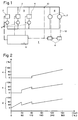
- Fig. 1 shows a heating system 1 with three heat generators 2, 3 and 4, which are arranged in parallel are arranged in a generator circuit 5.
- the generator circuit 5 is connected to a consumer circuit 6 connected to several consumers 7.
- the consumers 7 are, for example, heating circuits, hot water tanks, Heat exchangers, etc., which are regulated by consumer regulators 8.
- Each of the heat generators A separate circulation pump 9 is assigned to 2, 3 and 4. But it can also only be a single one common flow or return of the generator circuit 5 arranged circulation pump is provided be.
- a temperature sensor 10 is used to measure the actual temperature in the flow of the consumer circuit 6 available.
- the heat generators 2-4 and the circulating pumps 9 are operated by a control and regulating device 11 controlled.
- the control and regulating device 11, the heat generators 2, 3 and 4, the circulation pumps 9, the temperature sensor 10, the consumer controller 8 and other consumer components such as Valves are connected to one another via a bidirectional bus 12.
- the control and regulating device 11 is in connection with the consumer regulators 8, which indicate which Target temperature of the flow should have. From the target temperatures required by the consumer controllers The control and regulating device 11 determines the highest and controls the heat generators 2, 3 and 4 such that the difference between the highest target temperature and the measured actual temperature disappears. For this purpose, each of the heat generators 2, 3 and 4 specifies which heating output to be provided by him. The specification is made e.g. in percent of the nominal power or in absolute Performance values.
- each of the heat generators 2, 3 and 4 is defined by a performance range which specifies the performance limits within which the heat generator works optimally with regard to various parameters such as efficiency, risk of corrosion, etc.
- the optimal power range is preferably defined by the specification of the nominal power L N and a minimum and a maximum value L min or L max in percent of the nominal power.
- the control and regulating device 11 is set up to control any number of identical heat generators. It accordingly contains storage means for storing the optimum power range associated with these heat generators.
- the control and regulating device 11 In order to provide the heating power of 30 kW, the control and regulating device 11 thus specifies a heating power of 30% of the nominal power L N of 50 kW for the two condensing boilers 2 and 3. If the heat demand continues to rise and exceeds a heating output of 60 kW, ie 2 * 60% of the nominal output L N of 50 kW of the two condensing boilers 2 and 3 that are switched on, then the control and regulating device 11 switches on the third condensing boiler 4 and gives it to everyone the condensing boiler 2, 3 and 4 have a heating output of 40%. This mode of operation ensures that condensing boilers 2, 3 and 4 always work as ecologically and economically as possible. Since the connection of another heat generator does not take place only when the heat generators that are already switched on are 100% of their output, the required heat requirement can be covered at any time. The response times of the overall system to changes in heat demand are therefore equally short across the entire performance range.
- the control and regulating device 11 switches the third Condensing boiler 4 again.
- the third heat generator 4 is switched off with a total heating power that is slightly below the total heating power at which the third heat generator 4 is switched on. Such a switching difference is also for the switch-on and switch-off point of the second heat generator 3 intended.
- FIG. 2 shows in a circuit diagram which heating output each of the three heat generators 2, 3 and 4 has to provide as a function of the required total heating output.
- the circuit diagram therefore indicates the operating state - switched on or switched off - and the performance status of each of the heat generators (2, 3, 4) as a function of the total output of the heating system (1).
- the switching difference required for switching the second and third heat generators 3 and 4 on and off is not shown.
- both heat generators 2 and 3 are operated with the same power, ie started up in parallel.
- all three heat generators 2, 3 and 4 are operated with the same power. It is important that the three heat generators 2, 3 and 4 together exceed the upper limit L max of 60% of the nominal output.
- the control and regulating device 11 is set up to control any number of different heat generators.
- the control and regulating device 11 therefore maintains a table with the power bands of the heat generators 2, 3 and 4 to be controlled. From the data stored in the table, the control and regulating device 11 automatically determines which output of which or which of the heat generators 2, 3 is used and 4 must be in operation and what performance they must provide. This is explained in more detail using an example. The following table applies if the heat generator 2 and 3 is a condensing boiler and the heat generator 4 is a modulating gas burner.
- the numbers of the heat generators indicate in which order the heat generators are switched on should be.
- control and regulating device 11 could also be set up with regular ones Load changes (such as when changing from night setback to daytime operation) for the heat generators 2, 3 and 4 to directly specify the power that was used the previous day in the same load case was required.
- the data on the optimal mode of operation the heat generator 2, 3 and 4 are stored by the manufacturer of the same in the heat generator and can be queried by the control and regulating device 11 via the bus 12.
- the tax and Control unit 11 preferably automatically, how many heat generators are present, for example by counting how many bus addresses are occupied by heat generators.
- the tax and Control device 11 also set up to independently determine the order in which the heat generator to be put into operation.
Landscapes
- Engineering & Computer Science (AREA)
- Physics & Mathematics (AREA)
- Thermal Sciences (AREA)
- Chemical & Material Sciences (AREA)
- Combustion & Propulsion (AREA)
- Mechanical Engineering (AREA)
- General Engineering & Computer Science (AREA)
- Steam Or Hot-Water Central Heating Systems (AREA)
Priority Applications (1)
| Application Number | Priority Date | Filing Date | Title |
|---|---|---|---|
| EP97115571A EP0900988A1 (fr) | 1997-09-06 | 1997-09-06 | Méthode pour contrÔler une installation de chauffage avec plusieurs générateurs de chaleur |
Applications Claiming Priority (1)
| Application Number | Priority Date | Filing Date | Title |
|---|---|---|---|
| EP97115571A EP0900988A1 (fr) | 1997-09-06 | 1997-09-06 | Méthode pour contrÔler une installation de chauffage avec plusieurs générateurs de chaleur |
Publications (1)
| Publication Number | Publication Date |
|---|---|
| EP0900988A1 true EP0900988A1 (fr) | 1999-03-10 |
Family
ID=8227327
Family Applications (1)
| Application Number | Title | Priority Date | Filing Date |
|---|---|---|---|
| EP97115571A Withdrawn EP0900988A1 (fr) | 1997-09-06 | 1997-09-06 | Méthode pour contrÔler une installation de chauffage avec plusieurs générateurs de chaleur |
Country Status (1)
| Country | Link |
|---|---|
| EP (1) | EP0900988A1 (fr) |
Cited By (4)
| Publication number | Priority date | Publication date | Assignee | Title |
|---|---|---|---|---|
| DE102007063137A1 (de) * | 2007-12-24 | 2009-06-25 | Lang, Jürgen, Dipl.-Ing. | Wärmeversorgungsanlage mit mindestens zwei Wärmeerzeugern für mindestens zwei auf unterschiedlichen Temperaturebenen arbeitende Wärmeenergieversorgungskreise und Verfahren zur verbrauchsabhängigen Regelung der Wärmeerzeuger |
| EP2189729A3 (fr) * | 2008-11-25 | 2013-10-02 | Viessmann Werke GmbH & Co. KG | Procédé de fonctionnement d'une installation de chauffage |
| EP2416083A4 (fr) * | 2009-03-30 | 2015-11-04 | Mitsubishi Electric Corp | Système et procédé de chauffage de fluide, et système de commande, dispositif de commande et procédé de commande de chauffage de fluide |
| DE102018120992A1 (de) * | 2018-08-28 | 2020-03-05 | Walerij Schlagin | Brennereinheit für eine Heizungsanlage |
Citations (2)
| Publication number | Priority date | Publication date | Assignee | Title |
|---|---|---|---|---|
| DE3517902A1 (de) * | 1985-04-23 | 1986-10-23 | LGZ Landis & Gyr Zug AG, Zug | Verfahren zur leistungsmaessig gesteuerten inbetriebnahme bzw. abschaltung von heizkesseln |
| US5172654A (en) * | 1992-02-10 | 1992-12-22 | Century Controls, Inc. | Microprocessor-based boiler controller |
-
1997
- 1997-09-06 EP EP97115571A patent/EP0900988A1/fr not_active Withdrawn
Patent Citations (2)
| Publication number | Priority date | Publication date | Assignee | Title |
|---|---|---|---|---|
| DE3517902A1 (de) * | 1985-04-23 | 1986-10-23 | LGZ Landis & Gyr Zug AG, Zug | Verfahren zur leistungsmaessig gesteuerten inbetriebnahme bzw. abschaltung von heizkesseln |
| US5172654A (en) * | 1992-02-10 | 1992-12-22 | Century Controls, Inc. | Microprocessor-based boiler controller |
Cited By (4)
| Publication number | Priority date | Publication date | Assignee | Title |
|---|---|---|---|---|
| DE102007063137A1 (de) * | 2007-12-24 | 2009-06-25 | Lang, Jürgen, Dipl.-Ing. | Wärmeversorgungsanlage mit mindestens zwei Wärmeerzeugern für mindestens zwei auf unterschiedlichen Temperaturebenen arbeitende Wärmeenergieversorgungskreise und Verfahren zur verbrauchsabhängigen Regelung der Wärmeerzeuger |
| EP2189729A3 (fr) * | 2008-11-25 | 2013-10-02 | Viessmann Werke GmbH & Co. KG | Procédé de fonctionnement d'une installation de chauffage |
| EP2416083A4 (fr) * | 2009-03-30 | 2015-11-04 | Mitsubishi Electric Corp | Système et procédé de chauffage de fluide, et système de commande, dispositif de commande et procédé de commande de chauffage de fluide |
| DE102018120992A1 (de) * | 2018-08-28 | 2020-03-05 | Walerij Schlagin | Brennereinheit für eine Heizungsanlage |
Similar Documents
| Publication | Publication Date | Title |
|---|---|---|
| DE102008048258B4 (de) | Windpark und Verfahren zum Betreiben eines Windparks | |
| EP2913594B1 (fr) | Procédé de fonctionnement d'une installation de chauffage sans ballon tampon, en particulier destiné à garantir un fonctionnement fiable et correct | |
| DE3005209A1 (de) | Heizungsanlage | |
| DE102008057730A1 (de) | Verfahren zum Betreiben eines Systems zum Transport thermischer Energie über ein flüssiges Medium | |
| DE3709085A1 (de) | Verfahren zum steuern der vorlauftemperatur einer heizungsanlage | |
| DE19859364C2 (de) | Wärmeversorgungsanlage mit Spitzenlastbegrenzung | |
| DE2706852A1 (de) | Steuer- und ueberwachungseinrichtung fuer systeme zur uebergabe von waermeenergie | |
| EP0892223A2 (fr) | Dispositif de commande et de régulation pour système de chauffage | |
| DE4312808A1 (de) | Verfahren zur Steuerung einer Raumheizungsanlage und Vorrichtung | |
| EP0900988A1 (fr) | Méthode pour contrÔler une installation de chauffage avec plusieurs générateurs de chaleur | |
| DE3517902C2 (fr) | ||
| DE3311127C3 (de) | Verfahren zur Regelung von im Verbund geschalteten, mit einem Pufferspeicher verbundenen Wärmeerzeugern und Anordnung zur Durchführung des Verfahrens | |
| CH656210A5 (en) | Heat pump arrangement | |
| EP3139103B1 (fr) | Procédé de préparation de boissons chaudes | |
| CH663837A5 (de) | Verfahren zur regelung der temperatur eines waermetraegers sowie zur lastabhaengigen zu- oder abschaltung einzelner waermeerzeuger. | |
| EP3023709B1 (fr) | Procede de chauffage d'un fluide dans un reservoir dans une installation de chauffage et installation de chauffage associee | |
| DE10244256A1 (de) | Heizanlage und/oder Kühlanlage mit mindestens einer Wärmequelle | |
| WO2007036425A2 (fr) | Systeme de gestion de l'energie pour vehicule automobile | |
| CH681324A5 (fr) | ||
| EP0192228A2 (fr) | Procédé de régulation de température de locaux avec des dispositifs de chauffage et/ou de refroidissement | |
| DE3410316A1 (de) | Mehrkessel-heizungsanlage fuer fluessige waermetraegermedien | |
| EP0198222A2 (fr) | Procédé de répartition de puissance | |
| DE10348536B4 (de) | Anordnung zur Erwärmung von Brauchwasser | |
| AT391754B (de) | Verfahren zum betreiben mehrerer waerme- oder kaeltequellen mit gestufter leistung | |
| EP0916903A2 (fr) | Installation de chauffage de locaux et procédé pour son opération |
Legal Events
| Date | Code | Title | Description |
|---|---|---|---|
| PUAI | Public reference made under article 153(3) epc to a published international application that has entered the european phase |
Free format text: ORIGINAL CODE: 0009012 |
|
| AK | Designated contracting states |
Kind code of ref document: A1 Designated state(s): AT CH DE FR IT LI NL |
|
| AX | Request for extension of the european patent |
Free format text: AL;LT;LV;RO;SI |
|
| 17P | Request for examination filed |
Effective date: 19990910 |
|
| AKX | Designation fees paid |
Free format text: AT CH DE FR IT LI NL |
|
| RAP1 | Party data changed (applicant data changed or rights of an application transferred) |
Owner name: SIEMENS BUILDING TECHNOLOGIES AG |
|
| 17Q | First examination report despatched |
Effective date: 20010612 |
|
| STAA | Information on the status of an ep patent application or granted ep patent |
Free format text: STATUS: THE APPLICATION IS DEEMED TO BE WITHDRAWN |
|
| 18D | Application deemed to be withdrawn |
Effective date: 20011227 |