EP0901022B1 - Système d'imagerie de flux couleurs employant des ultrasons (CFM) et procédé de filtrage de signaux doppler pour système employant des ultrasons - Google Patents
Système d'imagerie de flux couleurs employant des ultrasons (CFM) et procédé de filtrage de signaux doppler pour système employant des ultrasons Download PDFInfo
- Publication number
- EP0901022B1 EP0901022B1 EP98116671A EP98116671A EP0901022B1 EP 0901022 B1 EP0901022 B1 EP 0901022B1 EP 98116671 A EP98116671 A EP 98116671A EP 98116671 A EP98116671 A EP 98116671A EP 0901022 B1 EP0901022 B1 EP 0901022B1
- Authority
- EP
- European Patent Office
- Prior art keywords
- auto
- outputs
- doppler signal
- ultrasonic
- processing portion
- Prior art date
- Legal status (The legal status is an assumption and is not a legal conclusion. Google has not performed a legal analysis and makes no representation as to the accuracy of the status listed.)
- Expired - Lifetime
Links
Images
Classifications
-
- A—HUMAN NECESSITIES
- A61—MEDICAL OR VETERINARY SCIENCE; HYGIENE
- A61B—DIAGNOSIS; SURGERY; IDENTIFICATION
- A61B8/00—Diagnosis using ultrasonic, sonic or infrasonic waves
- A61B8/06—Measuring blood flow
-
- G—PHYSICS
- G01—MEASURING; TESTING
- G01S—RADIO DIRECTION-FINDING; RADIO NAVIGATION; DETERMINING DISTANCE OR VELOCITY BY USE OF RADIO WAVES; LOCATING OR PRESENCE-DETECTING BY USE OF THE REFLECTION OR RERADIATION OF RADIO WAVES; ANALOGOUS ARRANGEMENTS USING OTHER WAVES
- G01S15/00—Systems using the reflection or reradiation of acoustic waves, e.g. sonar systems
- G01S15/88—Sonar systems specially adapted for specific applications
- G01S15/89—Sonar systems specially adapted for specific applications for mapping or imaging
- G01S15/8906—Short-range imaging systems; Acoustic microscope systems using pulse-echo techniques
- G01S15/8979—Combined Doppler and pulse-echo imaging systems
-
- G—PHYSICS
- G01—MEASURING; TESTING
- G01S—RADIO DIRECTION-FINDING; RADIO NAVIGATION; DETERMINING DISTANCE OR VELOCITY BY USE OF RADIO WAVES; LOCATING OR PRESENCE-DETECTING BY USE OF THE REFLECTION OR RERADIATION OF RADIO WAVES; ANALOGOUS ARRANGEMENTS USING OTHER WAVES
- G01S7/00—Details of systems according to groups G01S13/00, G01S15/00, G01S17/00
- G01S7/52—Details of systems according to groups G01S13/00, G01S15/00, G01S17/00 of systems according to group G01S15/00
- G01S7/52017—Details of systems according to groups G01S13/00, G01S15/00, G01S17/00 of systems according to group G01S15/00 particularly adapted to short-range imaging
- G01S7/52053—Display arrangements
- G01S7/52057—Cathode ray tube displays
- G01S7/52071—Multicolour displays; using colour coding; Optimising colour or information content in displays, e.g. parametric imaging
Definitions
- the present invention relates to an ultrasonic color flow mapping system and a method for filtering an ultrasonic Doppler signal.
- the ultrasonic diagnostic method uses an acousto-physical response or acousto-physical information of a living organism texture such as reflection, scattering and absorption occurring when an ultrasonic wave passes through the living organism texture.
- a Doppler method has been proposed as a method for realization of an ultrasonic scanned signal as an image.
- a diagnostic apparatus adopting the Doppler method displays a frequency shift amount together with a signal scattering intensity as images, to thereby estimate the circulation of blood in the living body.
- such a conventional diagnostic apparatus cannot but obtain only blood stream information of a constant depth according to the beam direction.
- the Doppler video system capable of displaying a color image demodulates a received signal and then digitizes the demodulation signal for processing, which can provide an excellent effect in which a blood stream flowing in the heart or a main blood vessel can be described as a two-dimensional (2D) image.
- the color Doppler video system can display both tomogram and blood stream information.
- the color Doppler video system displays the tomogram as monochrome and the blood stream information as color.
- the information of the blood stream flowing toward the direction of the scanned ultrasonic beam is displayed as the warm color and that of toward the counter-direction thereof is displayed as the cool color. Accordingly, the information of the blood stream can be displayed more accurately.
- the Doppler signal having demodulated by the above color Doppler video system contains a signal from a feeble blood stream having a relatively high frequency and a relatively small magnitude, and a signal from a soft texture having a relatively low frequency and a relatively large magnitude.
- the former is called a Doppler signal and the latter is called a clutter signal.
- a low-frequency signal that is, a clutter signal impedes an accurate detection of the blood stream information.
- the clutter signal should be properly removed.
- the clutter signal contains a very large direct-current (DC) component in general, and has several hundred times an amplitude as large as that of the Doppler signal, which has a bad influence upon an accurate image regeneration, as will be described later.
- the color Doppler video system uses a moving target indicator (MTI) filter being a kind of a high-pass filter, to remove such a clutter signal.
- MTI moving target indicator
- the MTI filter is a filter applied from the principle of an MTI radar, which is divided into an infinite impulse response (IIR) filter and a finite impulse response (FIR) filter.
- IIR infinite impulse response
- FIR finite impulse response
- the FIR filter adopts a relatively simple hardware structure and possesses a high stability with respect to a coefficient variation, with no transient phenomena, when compared with the IIR filter.
- the FIR filter has a very sluggish frequency characteristic curve, it is not so easy to determine a cut-off frequency necessary for removing the clutter signal.
- the IIR filter of the low degree can obtain a desired steep frequency characteristic curve relatively easily, which causes it to be widely used in real implementation.
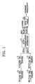
- Fig. 1 is a block diagram showing an ultrasonic color flow mapping system.
- Fig. 1 is an embodiment internal to the applicant, used as a comparative example but not representative of the prior art.
- the ultrasonic color flow mapping system includes a plurality of two-dimensional (2D) IIR filters 11 through 14, an auto-correlation estimator 15 and a look-up table 16.
- y n ⁇ 0 ⁇ x n + ⁇ 1 ⁇ x ⁇ n - 1 + ⁇ 2 ⁇ x ⁇ n - 2 - ⁇ 1 ⁇ y ⁇ n - 1 - ⁇ 2 ⁇ y ⁇ n - 2
- ⁇ 0 , ⁇ 1 , ⁇ 2 , ⁇ 1 and ⁇ 2 are filter coefficients which are variables properly set according to the characteristic of the filter.
- n 0, 1, ..., N-1
- a transient response with respect to the clutter signal which is removed by filtering it according as how x (-1), x (-2), y (-1) and y (-2) are defined, can be varied.
- the auto-correlation output of the auto-correlation estimator 15 according to the inputs I2(n) and Q2(n) in Fig. 1 is defined as the following equation (2).
- the auto-correlation R(0) from the auto-correlation estimator 15 is contributed for calculating the power of the Doppler signal and the auto-correlations Re(R(1)) and Im(R(1)) are contributed for calculating the average frequency of the Doppler signal through the look-up table 16.
- the color Doppler video system for the abdomen generally uses N of eight through 16, in order to calculate the average velocity and the power of the blood stream with respect to the pixel. Accordingly, although filtering is performed using the IIR filter, a transient response with respect to a feeble clutter signal still remains. Also, since the clutter signal is greater than the Doppler signal by 40 through 50dB, even a transient response with respect to the clutter signal can have a bad influence upon calculation of the blood stream velocity.
- n2 is equal to or greater than n1.
- D1 discloses an asymmetric FIR digital filter including a forward and a reverse section, in the forward section a group of input data samples is multiplied by a set of filter coefficients in a forward order to provide first intermediate results, which are summed to provide a first output sample. In the reverse section the same takes place in a reverse order to obtain a second output sample. The process is repeated to provide multiple first and second output samples.
- a signal estimation unit estimates the characteristics of the input data samples based on the first and second data output samples.
- D2 describes an ultrasonic color Doppler image system, particularly a filtering method for removing a clutter signal from an ultrasonic image.
- the first three signal output form the IIR filter are removed from a filter processing to improve the high IIR filter.
- D3 describes an ultrasonic diagnosis apparatus comprising an ultrasonic probe for scanning ultrasonic waves and receiving the reflected ultrasonic waves, a B-mode processor for detecting the intensity in the reflected ultrasonic waves, to obtain tomographic images, an MTI processor fro detecting a Doppler shift of the reflected waves to obtain blood flow data representing the velocity and direction of the blood in the tomographic image. Further two digital scan converters are used.
- D4 relates to a plurality of ultrasonic pulses transmitted to a living body by an ultrasonic probe, thus receiving an ultrasonic echo signal.
- An auto-correlating unit effects auto-correlation on the ultrasonic echo signal to produce a real-part component and imaginary-part component.
- a real-part component corrector adds an offset value to the real-part component so as to generate a new real-part component.
- a velocity detector detects a moving velocity of a tissue or blood from the real-part component and the imaginary-part component.
- the above method can effectively reduce the effect of the transient response with respect to the clutter signal, the number of data input to the auto-correlation estimator and used for the blood stream velocity calculation is reduced, which causes a reliable blood stream velocity and the relevant information not to be obtained.
- an object of the present invention (as defined by the claims) to provide an ultrasonic color flow mapping system and a filtering method for filtering an ultrasonic Doppler signal, in which a transient response with respect to a clutter signal included in the ultrasonic Doppler signal can be minimized, a reliable power and average frequency of the ultrasonic Doppler signal can be calculated since the number of data input to an auto-correlation estimator is not reduced, and thus an image such as a blood stream velocity can be accurately displayed on a real time basis.
- an ultrasonic color flow mapping system for regenerating an ultrasonic Doppler signal as an image
- the ultrasonic color flow mapping system comprising: a forward processing portion for excluding initial output data up to a predetermined number from outputs based on an ultrasonic Doppler signal input having a predetermined index sequence; a backward processing portion for excluding initial output data up to a predetermined number from outputs based on the ultrasonic Doppler signal input having a backward index sequence with respect to the input of the forward processing portion; and an operator for calculating a power and an average frequency of the ultrasonic Doppler signal based on the outputs of the forward and backward processing portions and providing the calculated result as an output for image regeneration.
- each of the forward processing portion and the backward processing portion comprises a filter portion having a plurality of infinite impulse response filters, for excluding the initial output data up to the predetermined number from the outputs from the upstream; and an auto-correlation estimator for auto-correlating the outputs from the filter portion and outputting the auto-correlation result to the operator.
- the operator comprises a plurality of subtracters/adders for adding the corresponding data to each other among the auto-correlation outputs from the respective auto-correlation estimators.
- a filtering method for regenerating an ultrasonic Doppler signal as an image comprising the steps of: excluding initial output data up to a predetermined number from outputs based on an ultrasonic Doppler signal input having a predetermined index sequence; excluding initial output data up to a predetermined number from outputs based on the ultrasonic Doppler signal input having a backward index sequence with respect to the input of the forward processing portion; and calculating a power and an average frequency of the ultrasonic Doppler signal based on the outputs of the forward and backward excluding steps and providing the calculated result as an output for image regeneration.
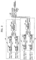
- an ultrasonic color flow mapping system includes a forward processing portion 20, a backward processing portion 30 and an operator 41 for operating outputs from respective auto-correlation estimators 27 and 37 in the forward and backward processing portions 20 and 30 and calculating a power and an average frequency of an ultrasonic Doppler signal.
- the operator 41 includes adders 43 and 45, a subtracter 47 and a look-up table 49.
- the forward processing portion 20 and the backward processing portion 30 includes filter portions 21 and 31 each having four 2'nd order IIR filters 23 through 26 and 33 through 36, and auto-correlation estimators 27 and 37, respectively.
- the forward processing portion 20 processes an ultrasonic Doppler color signal.
- If(n) and Qf(n) are same as the inputs I(n) and Q(n) of the Fig 1 .
- n2 is equal to or larger than n1, which are determined as experimental relevant values according to filter coefficients or system conditions.
- the effect of the transient response with respect to the clutter signal can be reduced in the forward processing portion 20, the number of the data input from the filter portion 21 to the auto-correlation estimator 27 and used for blood stream velocity calculation is reduced.
- the power and average frequency of the ultrasonic Doppler signal cannot be accurately detected with only the forward processing portion 20.
- the present invention includes a backward processing portion 30 having another filter portion 31 and another auto-correlation estimator 37 as shown in Fig. 2 .
- the backward processing portion 30 receives inputs I(N-n-1) and Q(N-n-1) each having a backward sequence with respect to the inputs I(n) and Q(n) of the forward processing portion 20.
- the signal processing of the backward processing portion 30 is performed using the inputs I(N-n-1) and Q(N-n-1) each having the backward sequence, in the same manner as that of the forward processing portion 20.
- the backward processing portion 30 excludes several data which can reduce the effect of the transient response with respect to the clutter signal among the inputs to the auto-correlation estimator 37, that is, the outputs filtered by second and fourth 2'nd order IIR filters 34 and 36.
- the number of the data input to the auto-correlation estimator 37 and used for calculating the blood stream velocity is reduced and as a result the power and average frequency of the ultrasonic Doppler signal cannot be accurately detected in itself.
- the outputs of the respective processing portions 20 and 30, that is, the auto-correlation outputs of the auto-correlation estimators 27 and 37 are added to each other in the operator 41 or subtracted from each other.
- the auto-correlations R(0)s from the auto-correlation estimators 27 and 37 are added to each other in a first adder 43 and then is used for calculating the power of the Doppler signal.
- the auto-correlations Re(R(1))s from the auto-correlation estimators 27 and 37 are added to each other in a second adder 45 and the auto-correlations Im(R(1))s from the auto-correlation estimators 27 and 37 are added to each other in a first subtracter 47.
- the signs of the auto-correlations Im(R(1)) output from the auto-correlation estimators 27 and 37 reverse to each other.
- the first subtracter 47 performs a subtraction operation, by which the substantially same result as an addition operation is obtained.
- the output having passed through the look-up table 49 after being added in the second adder 45 and subtracted in the first subtracter 47 is used for calculating the average frequency of the Doppler signal.
- n1 and n2 are increased to a degree, e. g., about N/2 or so, an effect of the transient response with respect to the clutter signal is gradually reduced and thus the outputs of the auto-correlation estimators 27 and 37 become more independent.
- the outputs of the auto-correlation estimators 27 and 37 are added to each other or subtracted from each other, the same effect as when no data is not excluded in the processing portions 20 and 30 can be obtained.
- the power and average frequency of the ultrasonic Doppler signal can be accurately calculated on the basis of a relatively more number of data.
- an image such as a blood stream velocity can be accurately regenerated on a real time basis.
- a signal conversion portion for converting the input signal to inputs I(N-n-1) and Q(N-n-1), and for providing them to the backward processing portion 30. Further, it is preferable to provide a synchronous portion(not shown) ahead of the forward processing portion 20 so as to synchronize the forward signal inputted to the forward processing portion 20 with the backward signal inputed to the backward processing portion 30.
Landscapes
- Engineering & Computer Science (AREA)
- Physics & Mathematics (AREA)
- Radar, Positioning & Navigation (AREA)
- Remote Sensing (AREA)
- Acoustics & Sound (AREA)
- Computer Networks & Wireless Communication (AREA)
- General Physics & Mathematics (AREA)
- Health & Medical Sciences (AREA)
- Life Sciences & Earth Sciences (AREA)
- Pathology (AREA)
- Surgery (AREA)
- Nuclear Medicine, Radiotherapy & Molecular Imaging (AREA)
- Hematology (AREA)
- Radiology & Medical Imaging (AREA)
- Biomedical Technology (AREA)
- Heart & Thoracic Surgery (AREA)
- Medical Informatics (AREA)
- Molecular Biology (AREA)
- Biophysics (AREA)
- Animal Behavior & Ethology (AREA)
- General Health & Medical Sciences (AREA)
- Public Health (AREA)
- Veterinary Medicine (AREA)
- Ultra Sonic Daignosis Equipment (AREA)
- Image Processing (AREA)
- Image Analysis (AREA)
Claims (4)
- Système de mappage de flux de couleur ultrasonore pour régénérer un signal ultrasonore Doppler en tant qu'image, le système de mappage de flux de couleur ultrasonore comprenant une partie de traitement avant (20), une partie de traitement arrière (30), un opérateur (41) pour calculer une puissance et une fréquence moyenne du signal ultrasonore Doppler sur la base des sorties de la partie de traitement avant (20) et de la partie de traitement arrière (30) et pour fournir le résultat calculé en tant que sortie pour une régénération d'image ; caractérisé en ce quela partie de traitement avant (20) exclut, des sorties, des données de sortie initiales jusqu'à un nombre prédéterminé sur la base d'une entrée de signal ultrasonore Doppler ayant une séquence d'index prédéterminée ;la partie de traitement arrière (30) exclut, des sorties, des données de sortie initiales jusqu'à un nombre prédéterminé sur la base de l'entrée de signal ultrasonore Doppler ayant une séquence d'index arrière par rapport à l'entrée de la partie de traitement avant (20) ;chacune de ladite partie de traitement avant (20) et de ladite partie de traitement arrière (30) comprend :une partie formant filtre (21, 31) comportant une pluralité de filtres à réponse impulsionnelle infinie (23 à 26, 33 à 36), chacun d'eux excluant, des sorties, des données de sortie initiales jusqu'à un nombre prédéterminé à partir de l'amont ; etun estimateur d'auto-corrélation (27, 37) pour auto-corréler les sorties des parties formant filtres (21, 31) ; If2(n), Qf2(n) étant la sortie de la partie formant filtre de la partie de traitement avant, Ib2(n), Qb2(n) étant la sortie de la partie formant filtre de la partie de traitement arrière,dans lequel l'estimateur d'auto-corrélation (27, 37) auto-corrèle les sorties I2(n), Q2(n) des parties formant filtres (21, 31) et délivre le résultat de l'auto-corrélation à l'opérateur (41) conformément aux équations suivantes :


 l'opérateur (41) comprend une pluralité de soustracteurs/additionneurs (43, 45, 47) pour additionner les données correspondantes les uns aux autres parmi les sorties d'auto-corrélation des estimateurs d'auto-corrélation (27, 37) respectifs, et une table de correspondance (49), dans lequel les sorties d'auto-corrélation R(0) des estimateurs d'auto-corrélation (27) et (37) sont additionnées dans un additionneur (43) pour calculer la puissance du signal Doppler,les sorties d'auto-corrélation Re(R(1)) des estimateurs d'auto-corrélation (27) et (37) sont additionnées dans un additionneur (45),les sorties Im(R(1)) des estimateurs d'auto-corrélation (27) et (37) sont soustraites dans un soustracteur (47),les sorties de l'additionneur (45) et du soustracteur (47) passant à travers une table de correspondance (49) pour calculer la fréquence moyenne du signal Doppler.
 - Système de mappage de flux de couleur ultrasonore selon la revendication 1, dans lequel la sortie dudit premier additionneur (43) est utilisée pour calculer la puissance du signal ultrasonore Doppler, et les sorties dudit deuxième additionneur (45) et dudit premier soustracteur (47) sont utilisées pour calculer la fréquence moyenne du signal ultrasonore Doppler.
- Système de mappage de flux de couleur ultrasonore selon les revendications 1 - 2, dans lequel ledit signal ultrasonore Doppler est un signal réfléchi par un corps vivant.
- Procédé de filtrage pour régénérer un signal ultrasonore Doppler en tant qu'image, le procédé de filtrage comprenant les étapes consistant à :exclure, des sorties, des données de sortie initiales jusqu'à un nombre prédéterminé sur la base d'une entrée de signal ultrasonore Doppler ayant une séquence d'index prédéterminée ;dans lequel l'entrée ayant un index prédéterminé passe à travers une partie formant filtre comportant une pluralité de filtres à réponse impulsionnelle infinie,chacun d'eux excluant, des sorties, des données de sortie initiales jusqu'à un nombre prédéterminé de l'amont,auto-corréler les parties des données de sortie initiales qui ne sont pas exclues If2(n), Qf2(n) pour produire des sorties d'auto-corrélation R(0), Re(R(1)) et Im(R(1)) conformément aux équations suivantes :


 exclure, des sorties, les données de sortie initiales jusqu'à un nombre prédéterminé sur la base de l'entrée de signal ultrasonore Doppler ayant une séquence d'index arrière par rapport à la séquence d'index prédéterminée ;dans lequel l'entrée ayant la séquence d'index arrière passe à travers une partie formant filtre comportant une pluralité de filtres à réponse impulsionnelle infinie,chacun d'eux excluant, des sorties, les données de sortie initiales jusqu'à un nombre prédéterminé de l'amont,auto-corréler les parties des données de sortie initiales qui ne sont pas exclues, Ib2(n), Qb2(n) pour produire des sorties d'auto-corrélation R(0), Re(R(1)) et Im(R(1)) conformément aux équations suivantes :

 calculer une puissance et une fréquence moyenne du signal ultrasonore Doppler sur la base des sorties des étapes d'exclusion et fournir le résultat calculé en tant que sortie pour une régénération d'image ;dans lequel ladite étape de calcul comprend les étapes suivantes :additionner et soustraire les sorties auto-corrélées desdites étapes d'exclusion pour déterminer la puissance et la fréquence moyenne du signal ultrasonore Doppler, dans lequel les sorties d'auto-corrélation R(0) sont additionnées dans un additionneur pour calculer la puissance du signal Doppler, les sorties d'auto-corrélation Re(R(1)) sont additionnées dans un additionneur et les sorties Im(R(1)) sont soustraites dans un soustracteur et elles passent à travers une table de correspondance pour calculer la fréquence moyenne du signal Doppler.
Applications Claiming Priority (2)
| Application Number | Priority Date | Filing Date | Title |
|---|---|---|---|
| KR1019970045844A KR100232257B1 (ko) | 1997-09-04 | 1997-09-04 | 클러터신호의 과도응답을 최소로 하는 초음파칼라도플러영상시스템 |
| KR9745844 | 1997-09-04 |
Publications (3)
| Publication Number | Publication Date |
|---|---|
| EP0901022A2 EP0901022A2 (fr) | 1999-03-10 |
| EP0901022A3 EP0901022A3 (fr) | 1999-11-03 |
| EP0901022B1 true EP0901022B1 (fr) | 2010-02-24 |
Family
ID=19520880
Family Applications (1)
| Application Number | Title | Priority Date | Filing Date |
|---|---|---|---|
| EP98116671A Expired - Lifetime EP0901022B1 (fr) | 1997-09-04 | 1998-09-03 | Système d'imagerie de flux couleurs employant des ultrasons (CFM) et procédé de filtrage de signaux doppler pour système employant des ultrasons |
Country Status (5)
| Country | Link |
|---|---|
| US (1) | US6126604A (fr) |
| EP (1) | EP0901022B1 (fr) |
| JP (1) | JP3011691B2 (fr) |
| KR (1) | KR100232257B1 (fr) |
| DE (1) | DE69841516D1 (fr) |
Families Citing this family (15)
| Publication number | Priority date | Publication date | Assignee | Title |
|---|---|---|---|---|
| US6277075B1 (en) * | 1999-11-26 | 2001-08-21 | Ge Medical Systems Global Technology Company, Llc | Method and apparatus for visualization of motion in ultrasound flow imaging using continuous data acquisition |
| JP4723712B2 (ja) * | 2000-09-22 | 2011-07-13 | 株式会社東芝 | 超音波診断装置 |
| CN100367915C (zh) * | 2004-03-15 | 2008-02-13 | 深圳迈瑞生物医疗电子股份有限公司 | 基于反向初始化iir的彩色血流成像壁滤波方法和装置 |
| US7118532B2 (en) * | 2004-05-06 | 2006-10-10 | General Electric Company | Data dependent color wall filters |
| EP2613170A1 (fr) * | 2004-12-30 | 2013-07-10 | CrystalView Medical Imaging Limited | Suppression d'échos parasites dans des systèmes d'imagerie ultrasonore |
| US9451932B2 (en) | 2004-12-30 | 2016-09-27 | Crystalview Medical Imaging Limited | Clutter suppression in ultrasonic imaging systems |
| JP4644011B2 (ja) * | 2005-03-15 | 2011-03-02 | パナソニック株式会社 | 超音波ドプラ血流計 |
| KR20090042152A (ko) * | 2007-10-25 | 2009-04-29 | 주식회사 메디슨 | 사이드 로브 레벨의 영향을 제거하는 방법 |
| EP2053420B1 (fr) | 2007-10-25 | 2012-12-05 | Samsung Medison Co., Ltd. | Procédé de suppression d'un effet de lobes latéraux dans la formation d'une image synthétique à ultrasons par estimation et compensation de l'influence de mouvement |
| EP2053419B1 (fr) * | 2007-10-25 | 2012-10-17 | Samsung Medison Co., Ltd. | Appareil et procédé d'évaluation et de compensation d'un mouvement dans la formation d'une image synthétique en utilisant une séquence particulière de lignes explorées |
| CN104272134B (zh) * | 2012-02-29 | 2017-05-31 | 克里斯塔韦尔医学影像有限公司 | 超声成像系统中的杂波抑制 |
| JP5489144B1 (ja) * | 2012-04-27 | 2014-05-14 | コニカミノルタ株式会社 | ビームフォーミング方法、及び超音波診断装置 |
| KR101622543B1 (ko) * | 2015-11-27 | 2016-05-19 | 자인테크놀로지(주) | 파이프 두께 자동 측정 기능을 구비하는 외벽 부착식 초음파 유량계 |
| CN114376606B (zh) | 2022-01-18 | 2023-05-09 | 武汉联影医疗科技有限公司 | 一种超声成像的滤波方法和系统 |
| CN114793104B (zh) * | 2022-04-28 | 2025-05-16 | 飞依诺科技股份有限公司 | 彩色血流成像的壁滤波方法 |
Citations (1)
| Publication number | Priority date | Publication date | Assignee | Title |
|---|---|---|---|---|
| US5188113A (en) * | 1990-04-04 | 1993-02-23 | Kabushiki Kaisha Toshiba | Ultrasonic diagnosis apparatus |
Family Cites Families (5)
| Publication number | Priority date | Publication date | Assignee | Title |
|---|---|---|---|---|
| JPH0613031B2 (ja) * | 1987-08-12 | 1994-02-23 | 株式会社東芝 | 超音波血流イメ−ジング装置 |
| JPH04336056A (ja) * | 1991-05-10 | 1992-11-24 | Matsushita Electric Ind Co Ltd | 超音波ドプラ映像装置 |
| US5249578A (en) * | 1992-09-15 | 1993-10-05 | Hewlett-Packard Company | Ultrasound imaging system using finite impulse response digital clutter filter with forward and reverse coefficients |
| KR0178095B1 (ko) * | 1995-05-08 | 1999-04-01 | 이민화 | 초음파 칼라 도플러 영상시스템을 위한 필터링방법 |
| US5483964A (en) * | 1995-05-15 | 1996-01-16 | Ge Yokogawa Medical Systems, Ltd. | Method of detecting moving velocity of tissue or blood and ultrasonic diagnosing apparatus |
-
1997
- 1997-09-04 KR KR1019970045844A patent/KR100232257B1/ko not_active Expired - Fee Related
-
1998
- 1998-09-03 EP EP98116671A patent/EP0901022B1/fr not_active Expired - Lifetime
- 1998-09-03 JP JP10250005A patent/JP3011691B2/ja not_active Expired - Lifetime
- 1998-09-03 DE DE69841516T patent/DE69841516D1/de not_active Expired - Lifetime
- 1998-09-03 US US09/148,036 patent/US6126604A/en not_active Expired - Lifetime
Patent Citations (1)
| Publication number | Priority date | Publication date | Assignee | Title |
|---|---|---|---|---|
| US5188113A (en) * | 1990-04-04 | 1993-02-23 | Kabushiki Kaisha Toshiba | Ultrasonic diagnosis apparatus |
Also Published As
| Publication number | Publication date |
|---|---|
| EP0901022A3 (fr) | 1999-11-03 |
| KR100232257B1 (ko) | 1999-12-01 |
| KR19990024624A (ko) | 1999-04-06 |
| EP0901022A2 (fr) | 1999-03-10 |
| US6126604A (en) | 2000-10-03 |
| JPH11155860A (ja) | 1999-06-15 |
| DE69841516D1 (de) | 2010-04-08 |
| JP3011691B2 (ja) | 2000-02-21 |
Similar Documents
| Publication | Publication Date | Title |
|---|---|---|
| US5609155A (en) | Energy weighted parameter spatial/temporal filter | |
| JP3946288B2 (ja) | 超音波カラードプラ診断装置および超音波カラードプライメージングの信号処理方法 | |
| EP1188068B1 (fr) | Procede et appareil de suppression d'eclairs dans une imagerie ultrasonore bidimensionnelle | |
| JP4722283B2 (ja) | 連続データ獲得を用いた超音波フロー・イメージングにおける運動の可視化のための方法および装置 | |
| US6689064B2 (en) | Ultrasound clutter filter | |
| US5899864A (en) | Adaptive temporal filtering to enhance fluid flow or tissue motion imaging | |
| US5653234A (en) | Method and apparatus for adaptive spatial image filtering | |
| US6126604A (en) | Ultrasonic color flow mapping(CFM) system and ultrasonic doppler signal filtering method | |
| JP4627366B2 (ja) | パケット・データ獲得を用いた超音波フロー撮像における運動の可視化のための方法および装置 | |
| Thomas et al. | An improved wall filter for flow imaging of low velocity flow | |
| JP3724846B2 (ja) | 超音波診断装置 | |
| US6773403B2 (en) | Ultrasonic apparatus and method for measuring the velocities of human tissues using the doppler effects | |
| WO2003104843A1 (fr) | Systeme d'imagerie de diagnostic a ultrasons pour des agents de contraste a faible debit | |
| US6210334B1 (en) | Medical diagnostic ultrasound method and apparatus for harmonic detection using doppler processing | |
| WO1996021196A9 (fr) | Filtrage temporel adaptatif permettant d'ameliorer la visualisation de flux de fluides ou du mouvement de tissus | |
| EP2078494B1 (fr) | Réduction sonore et compensation de repliement dans une image de mode doppler | |
| JP3486243B2 (ja) | 超音波診断装置 | |
| KR0178095B1 (ko) | 초음파 칼라 도플러 영상시스템을 위한 필터링방법 | |
| JP3281435B2 (ja) | 超音波ドプラ診断装置 | |
| JP3000823B2 (ja) | 超音波ドプラ血流計 | |
| JP3697289B2 (ja) | 超音波ドプラ診断装置 | |
| JP2723458B2 (ja) | 超音波ドプラ診断装置 | |
| EP1627602A1 (fr) | Dispositif ultrasonographique et procede de traitement de donnees dudit dispositif ultrasonographique | |
| JP3042964B2 (ja) | 超音波ドプラ診断装置 | |
| Keenan et al. | Removal of wall-motion artefacts in Doppler ultrasound signals using linear prediction filtering |
Legal Events
| Date | Code | Title | Description |
|---|---|---|---|
| PUAI | Public reference made under article 153(3) epc to a published international application that has entered the european phase |
Free format text: ORIGINAL CODE: 0009012 |
|
| AK | Designated contracting states |
Kind code of ref document: A2 Designated state(s): DE FR GB IT NL |
|
| AX | Request for extension of the european patent |
Free format text: AL;LT;LV;MK;RO;SI |
|
| PUAL | Search report despatched |
Free format text: ORIGINAL CODE: 0009013 |
|
| AK | Designated contracting states |
Kind code of ref document: A3 Designated state(s): AT BE CH CY DE DK ES FI FR GB GR IE IT LI LU MC NL PT SE |
|
| AX | Request for extension of the european patent |
Free format text: AL;LT;LV;MK;RO;SI |
|
| 17P | Request for examination filed |
Effective date: 20000407 |
|
| AKX | Designation fees paid |
Free format text: DE FR GB IT NL |
|
| 17Q | First examination report despatched |
Effective date: 20041207 |
|
| 17Q | First examination report despatched |
Effective date: 20041207 |
|
| GRAP | Despatch of communication of intention to grant a patent |
Free format text: ORIGINAL CODE: EPIDOSNIGR1 |
|
| GRAS | Grant fee paid |
Free format text: ORIGINAL CODE: EPIDOSNIGR3 |
|
| GRAA | (expected) grant |
Free format text: ORIGINAL CODE: 0009210 |
|
| AK | Designated contracting states |
Kind code of ref document: B1 Designated state(s): DE FR GB IT NL |
|
| REG | Reference to a national code |
Ref country code: GB Ref legal event code: FG4D |
|
| REF | Corresponds to: |
Ref document number: 69841516 Country of ref document: DE Date of ref document: 20100408 Kind code of ref document: P |
|
| REG | Reference to a national code |
Ref country code: NL Ref legal event code: VDEP Effective date: 20100224 |
|
| PG25 | Lapsed in a contracting state [announced via postgrant information from national office to epo] |
Ref country code: NL Free format text: LAPSE BECAUSE OF FAILURE TO SUBMIT A TRANSLATION OF THE DESCRIPTION OR TO PAY THE FEE WITHIN THE PRESCRIBED TIME-LIMIT Effective date: 20100224 |
|
| PLBE | No opposition filed within time limit |
Free format text: ORIGINAL CODE: 0009261 |
|
| STAA | Information on the status of an ep patent application or granted ep patent |
Free format text: STATUS: NO OPPOSITION FILED WITHIN TIME LIMIT |
|
| 26N | No opposition filed |
Effective date: 20101125 |
|
| GBPC | Gb: european patent ceased through non-payment of renewal fee |
Effective date: 20100903 |
|
| PG25 | Lapsed in a contracting state [announced via postgrant information from national office to epo] |
Ref country code: GB Free format text: LAPSE BECAUSE OF NON-PAYMENT OF DUE FEES Effective date: 20100903 |
|
| REG | Reference to a national code |
Ref country code: FR Ref legal event code: PLFP Year of fee payment: 19 |
|
| REG | Reference to a national code |
Ref country code: FR Ref legal event code: PLFP Year of fee payment: 20 |
|
| PGFP | Annual fee paid to national office [announced via postgrant information from national office to epo] |
Ref country code: IT Payment date: 20170918 Year of fee payment: 20 Ref country code: DE Payment date: 20170810 Year of fee payment: 20 Ref country code: FR Payment date: 20170811 Year of fee payment: 20 |
|
| REG | Reference to a national code |
Ref country code: DE Ref legal event code: R071 Ref document number: 69841516 Country of ref document: DE |