EP0901030A1 - Dispositif d'affichage d'image - Google Patents
Dispositif d'affichage d'image Download PDFInfo
- Publication number
- EP0901030A1 EP0901030A1 EP97949233A EP97949233A EP0901030A1 EP 0901030 A1 EP0901030 A1 EP 0901030A1 EP 97949233 A EP97949233 A EP 97949233A EP 97949233 A EP97949233 A EP 97949233A EP 0901030 A1 EP0901030 A1 EP 0901030A1
- Authority
- EP
- European Patent Office
- Prior art keywords
- mirror
- image display
- display apparatus
- condenser lens
- color filter
- Prior art date
- Legal status (The legal status is an assumption and is not a legal conclusion. Google has not performed a legal analysis and makes no representation as to the accuracy of the status listed.)
- Granted
Links
- 230000003287 optical effect Effects 0.000 claims abstract description 78
- 238000005286 illumination Methods 0.000 claims abstract description 28
- 239000004973 liquid crystal related substance Substances 0.000 description 18
- 238000009826 distribution Methods 0.000 description 10
- 238000010276 construction Methods 0.000 description 6
- 230000006870 function Effects 0.000 description 5
- 238000005452 bending Methods 0.000 description 3
- 238000000034 method Methods 0.000 description 3
- 238000012634 optical imaging Methods 0.000 description 3
- 230000004075 alteration Effects 0.000 description 2
- 230000008901 benefit Effects 0.000 description 2
- 239000011521 glass Substances 0.000 description 2
- 239000000463 material Substances 0.000 description 2
- 230000008569 process Effects 0.000 description 2
- XAGFODPZIPBFFR-UHFFFAOYSA-N aluminium Chemical compound [Al] XAGFODPZIPBFFR-UHFFFAOYSA-N 0.000 description 1
- 229910052782 aluminium Inorganic materials 0.000 description 1
- 230000005540 biological transmission Effects 0.000 description 1
- 230000015572 biosynthetic process Effects 0.000 description 1
- 239000003086 colorant Substances 0.000 description 1
- 238000001816 cooling Methods 0.000 description 1
- 230000000694 effects Effects 0.000 description 1
- 230000005686 electrostatic field Effects 0.000 description 1
- 230000031700 light absorption Effects 0.000 description 1
- 238000004519 manufacturing process Methods 0.000 description 1
- 230000010287 polarization Effects 0.000 description 1
- 210000001747 pupil Anatomy 0.000 description 1
- 230000004044 response Effects 0.000 description 1
- 230000007480 spreading Effects 0.000 description 1
- 238000003892 spreading Methods 0.000 description 1
- 229910052724 xenon Inorganic materials 0.000 description 1
- FHNFHKCVQCLJFQ-UHFFFAOYSA-N xenon atom Chemical compound [Xe] FHNFHKCVQCLJFQ-UHFFFAOYSA-N 0.000 description 1
Images



Classifications
-
- G—PHYSICS
- G02—OPTICS
- G02B—OPTICAL ELEMENTS, SYSTEMS OR APPARATUS
- G02B26/00—Optical devices or arrangements for the control of light using movable or deformable optical elements
- G02B26/08—Optical devices or arrangements for the control of light using movable or deformable optical elements for controlling the direction of light
-
- H—ELECTRICITY
- H04—ELECTRIC COMMUNICATION TECHNIQUE
- H04N—PICTORIAL COMMUNICATION, e.g. TELEVISION
- H04N9/00—Details of colour television systems
- H04N9/12—Picture reproducers
- H04N9/31—Projection devices for colour picture display, e.g. using electronic spatial light modulators [ESLM]
- H04N9/3102—Projection devices for colour picture display, e.g. using electronic spatial light modulators [ESLM] using two-dimensional electronic spatial light modulators
- H04N9/3111—Projection devices for colour picture display, e.g. using electronic spatial light modulators [ESLM] using two-dimensional electronic spatial light modulators for displaying the colours sequentially, e.g. by using sequentially activated light sources
- H04N9/3114—Projection devices for colour picture display, e.g. using electronic spatial light modulators [ESLM] using two-dimensional electronic spatial light modulators for displaying the colours sequentially, e.g. by using sequentially activated light sources by using a sequential colour filter producing one colour at a time
-
- G—PHYSICS
- G02—OPTICS
- G02B—OPTICAL ELEMENTS, SYSTEMS OR APPARATUS
- G02B26/00—Optical devices or arrangements for the control of light using movable or deformable optical elements
- G02B26/08—Optical devices or arrangements for the control of light using movable or deformable optical elements for controlling the direction of light
- G02B26/0816—Optical devices or arrangements for the control of light using movable or deformable optical elements for controlling the direction of light by means of one or more reflecting elements
- G02B26/0833—Optical devices or arrangements for the control of light using movable or deformable optical elements for controlling the direction of light by means of one or more reflecting elements the reflecting element being a micromechanical device, e.g. a MEMS mirror, DMD
-
- H—ELECTRICITY
- H04—ELECTRIC COMMUNICATION TECHNIQUE
- H04N—PICTORIAL COMMUNICATION, e.g. TELEVISION
- H04N5/00—Details of television systems
- H04N5/74—Projection arrangements for image reproduction, e.g. using eidophor
-
- H—ELECTRICITY
- H04—ELECTRIC COMMUNICATION TECHNIQUE
- H04N—PICTORIAL COMMUNICATION, e.g. TELEVISION
- H04N5/00—Details of television systems
- H04N5/74—Projection arrangements for image reproduction, e.g. using eidophor
- H04N5/7416—Projection arrangements for image reproduction, e.g. using eidophor involving the use of a spatial light modulator, e.g. a light valve, controlled by a video signal
- H04N5/7458—Projection arrangements for image reproduction, e.g. using eidophor involving the use of a spatial light modulator, e.g. a light valve, controlled by a video signal the modulator being an array of deformable mirrors, e.g. digital micromirror device [DMD]
Definitions
- the present invention relates to a projection-type image display apparatus for use in a projection-type high-definition television system or video projector. More particularly, the present invention relates to an image display apparatus having a unique feature in the structure of the optical system for projecting a color image.
- One of known conventional projection-type image display apparatus is a projection-type color liquid-crystal display apparatus using a liquid-crystal display panel.
- the projection-type color liquid-crystal display apparatuses are roughly divided into a three-panel color liquid-crystal display apparatus having three liquid-crystal display panels for red, green and blue primaries and a single-panel color liquid-crystal display apparatus having a single liquid-crystal display panel with a mosaic- or stripe-patterned tricolor filter.
- the three-panel color liquid-crystal display apparatus comprises an optical system for converting a white light into red, green and blue primaries, and a liquid-crystal display panel for controlling luminance of each color to form an image.
- the final color image is produced and presented by optically superimposing red, green, and blue color images.
- the single-panel color liquid-crystal display apparatus introduces a white light into a single liquid-crystal display panel with a mosaic- or stripe-patterned tricolor filter to form and present a color image.
- DMD digital micromirror device
- the liquid-crystal panel used in the three-panel or single-panel projection-type liquid-crystal display apparatus controls a number of two-dimensionally arrayed cells of liquid-crystal molecules in orientation to vary polarization of light, thereby switching on and off the transmission of light.
- the above-cited DMD having a two-dimensional array of a number of pixels each having a micromirror, controls the tilt of each mirror individually through the effect of electrostatic field caused by a memory element arranged respectively for each pixel and varies the angle of reflection of reflected light ray thereby causing on/off state.
- FIG. 9 shows the operation of the micromirror arranged for each pixel in DMD.
- Diagrammatically shown in FIG. 9 are micromirrors 101 through 105 and a projection lens 110. As shown, the pixels corresponding to micromirrors 103 and 105 are in the on state.
- Light rays reflected off the micromirrors 101, 102, and 104 of pixels in the off state are not directed to the projection lens 110.
- Light rays reflected off the micromirrors 103 and 105 of the pixels in the on state are directed to the projection lens 110 and forms an image on a screen.
- the tilt angle of the micromirror of a pixel in the on state is 10 degrees or so with respect to a horizontally aligned micromirror.
- the advantages of DMD over the liquid-crystal display panel employing a polarizer include a better utilization of light, heat resistance property, high-speed response characteristics, and the like.
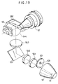
- FIG. 10 is a perspective view of an optical system for a conventional projection-type color image display apparatus using a DMD.
- a white light arc lamp (light emission point) 51 such as a xenon arc lamp is arranged at one focus of a collector ellipsoidal mirror 52.
- the light beam emitted from the arc lamp 51 is focused at the other focus of the ellipsoidal mirror 52, thereby forming a virtual secondary light source.
- a rotatable color filter 53 is placed at the position of the secondary light source (the other focus of the ellipsoidal mirror 52).
- the color filter 53 has a ring portion which is partitioned into transmission-type filters 53R, 53G and 53B correspondingly to three primaries of red, green and blue.
- Designated 531 is the axis of rotation of the color filter 53.
- the color filter 53 converts sequentially the white light into red, green and blue colors.
- a light beam passing through the color filter 53 is transmitted through condenser lenses 541, 542, reflected from a plane mirror 551, and transmitted through a condenser lens 543.
- the light beam transmitted through the condenser lens 543 is reflected from a plane mirror 552, transmitted through a condenser lens 544, and introduced into DMD 56.
- the light beam reflected from DMD 56 is admitted to a projection lens 57.
- the condenser lenses 541-544 have a function of condensing red, green or blue light beam at an entrance pupil of the projection lens 57 through the micromirrors of pixels in the on state of DMD 56. Furthermore, these condenser lenses 541-544 have a function of reducing nonuniform illumination caused by uneven illuminance on the screen.
- the plane mirrors 551 and 552 have a function of bending, in a three-dimensional space, the optical path of an optical illumination module that is complicatedly routed through the condenser lenses 541-544.
- the optical illumination module refers to an optical system constituted by components present in the optical path extending along the light beam from the arc lamp 51 to DMD 56.
- the reason the optical path of the optical illumination module is made complicated is as follows. To make DMD 56 to work correctly, the angle of incidence of a light beam to the surface of each micromirror in DMD 56 is necessarily great (80 degrees, for example), and as a result, the components constituting the optical illumination module, such as the condenser lenses, are subject to mechanical contact with or interference with the projection lens 57.
- the plane mirrors 551 and 552 are necessarily three-dimensionally placed, as shown in Fig. 10, thereby making complex the optical path of the optical illumination module.
- the central axis of DMD 56 is not colinearly aligned with the optical axis of the projection lens 57, and DMD 56 is offset (shifted) from the optical axis of the projection lens 57.
- the projection lens 57 is therefore used partially rather than in its full angle of view.
- the three-panel projection-type color image display apparatus is bulky and costly.
- the single-panel projection-type color display apparatus features a relatively simple optical structure and small component count, compact and low-cost design is easily implemented.
- the use of a color filter presents difficulty in full utilization of light beams from the light source and results in a darker image. If luminance of the light source is raised to compensate for this disadvantage, components such as the liquid-crystal panel must be provided with sufficient cooling steps.
- the conventional projection-type color image display apparatus using DMD is particularly heat-resistant, and presents a high resolution because of fine grid compared with the liquid-crystal display panel.
- the DMD color image display apparatus has the following disadvantages.
- the component count of the optical illumination module is so large that a potential high luminance image advantage of DMD cannot be fully exploited.
- optical illumination module is arranged three-dimensionally, assembly and adjustment process is time-consuming and the apparatus becomes bulky and costly.
- the image display apparatus of the present invention comprises a white-light source, a collector mirror for collecting a light beam from the white-light source to form a virtual secondary light source, a color filter, disposed at the position of the virtual secondary light source, for producing sequentially three primaries of light from the white-light beam, a condenser lens for allowing to be transmitted therethrough a light beam transmitted through the color filter, a reflecting mirror for reflecting the light beam transmitted through the condenser lens, reflection display means which receives the light beam reflected from the reflecting mirror and produces on and off states by varying the tilt of a micromirror of each of a number of two-dimensionally arrayed pixels to vary the angle of reflection of the light beam reflected therefrom, and a projection lens which receives the light beam reflected from a pixel in the on state and enlarges and projects the received light beam.
- the reflecting mirror is constituted by a single concave mirror such as a spherical or non-spherical mirror.
- a normal of the reflecting mirror at an intersection where the optical axis of the optical illumination module including the white-light source, the collector mirror and the condenser lens intersects the reflecting mirror is inclined by a predetermined angle.
- the optical components are arranged such that the optical axis of the projection lens is generally in parallel with the optical axis of the optical illumination module including the white-light source, the collector mirror, and the condenser lens.
- the optical components are arranged such that the optical axis of the projection lens lies in a plane perpendicular to the optical axis of the optical illumination module.
- the bending of the optical axis is only once performed by the reflecting mirror such as the spherical mirror or the non-spherical mirror.
- the construction of the optical illumination module is simple with a smaller component count.
- the assembly and adjustment process of the optical components is simplified, and compact and low-cost design is thus implemented.
- the reduced number of condenser lenses and reflecting mirrors lowers loss arising from light absorption and scattering, makes image luminance higher and improves color reproducibility (red color in particular).
- FIG. 1 shows the construction of the optical system of a first embodiment of the present invention.
- a white light arc lamp (light emission point) 51 is arranged at one focus of a collector ellipsoidal mirror 52.
- the light beam emitted from the arc lamp 51 is focused at the other focus of the ellipsoidal mirror 52.
- the light beam emitted from the arc lamp 51 is thus focused at the other focus of the ellipsoidal mirror 52, thereby forming a virtual secondary light source.
- a rotatable color filter 53 is placed at the position of the secondary light source (the other focus of the ellipsoidal mirror 52). As shown in FIG. 11, the color filter 53 has a ring portion which is partitioned into transmission-type filters 53R, 53G and 53B correspondingly to three primaries of red, green and blue.
- the light beam reflected from the ellipsoidal mirror 52 is introduced into the color filter 53.
- At least a condenser lens 1 (two condenser lenses, for example) having a positive refractive power and a spherical mirror 2 as a path bending mirror substitute for the four condenser lenses 541-544 and two plane mirrors 551 and 552 already described in connection with the conventional art with reference to FIG. 10.
- the spherical mirror 2 and DMD 56 are arranged such that the light beam reflected from the spherical mirror 2 enters DMD 56 at a high angle, namely a small angle of incidence.
- the condenser lens 1 a convex lens, has functions of guiding, to the spherical mirror 2, the light beam transmitted through the color filter 53 with the spreading of the light beam controlled and reducing nonuniform illumination on a screen 58.
- the condenser lens 1 may be coated with a heat-wave reflecting film or may be manufactured of a heat-resistant glass material capable of absorbing heat wave to eliminate unwanted heat wave coming in from the light source.
- a rod lens or flyeye integrator is preferably provided between the color filter 53 and the condenser lens 1 to reduce nonuniform illumination on the screen 58.
- the spherical mirror 2 has a concave surface as its reflecting surface, and is arranged to be out of alignment with the optical axis of the optical illumination module including the arc lamp 51, ellipsoidal mirror 52 and condenser lens 1.
- the phrase "out of alignment” means that the normal of the spherical mirror 2 where the optical axis of the arc lamp 51, ellipsoidal mirror 52 and condenser lens 1 intersects the reflecting surface of the spherical mirror 2 is inclined.
- the spherical mirror 2 has the functions of reflecting and converging the light beam transmitted through the condenser lens 1, and guiding the light beam to DMD 56 to introduce the light beam to DMD 56 at a high angle.
- the spherical mirror 2 is coated with aluminum film or is manufactured of a properly selected glass material to transmit the heat wave therethrough to remove it.
- the projection lens 57 includes lenses 571-574.
- Light beams (not shown) reflected from micromirrors of pixels in the off state are not introduced into the projection lens 57, thereby not contributing to image formation.
- micromirrors of the pixels in the on state are like micromirrors 103 and 105 shown in FIG. 9, and the micromirrors of the pixels in the off state are like micromirrors 101, 102, and 104 shown in FIG. 9.
- the color image is presented on the screen 58 using the color filter 53 and DMD 56 as described below.
- the micromirror of the pixel of a predetermined address in DMD 56 is turned on, and a light beam transmitted through the transmission-type filter 53R for red is reflected by the micromirror and introduced into the projection lens 57.
- the same method applies to present the image in green and in blue.
- Light beams transmitted through the transmission-type filters 53G and 53B for green and blue, respectively, are reflected by micromirrors of pixels in the on state of predetermined addresses and then introduced into the projection lens 57.
- a controller for issuing electrical signals to DMD 56 and a driver for the color filter 53 are not shown.
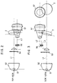
- FIG. 2 is a top view showing the actual mounted state of optical components of the first embodiment
- FIG. 3 is a side view showing the actual mounted state of the optical components of the first embodiment.
- FIG. 3 also shows on its right-hand portion a front view of the optical components.
- the optical axis L1 of the optical illumination module including the arc lamp 51, ellipsoidal mirror 52, color filter 53 and condenser lens 1, the optical axis L2 of the projection lens 57 constituting an optical imaging module, and the axis L3 perpendicular to the surface of incidence of DMD 56 as reflection display means are generally parallel in a three-dimensional space.
- the optical imaging module refers to an optical system constituted by components present in the optical path extending from DMD 56 to the projection lens 57 to the screen 58.
- the board When DMD 56 is mounted on a board, the board may block the optical axis L1 extending through the condenser lens 1.
- a second embodiment of the present invention has been developed to resolve such a problem.
- FIG. 4 shows the construction of the optical system of the second embodiment.
- the optical components of the optical illumination module and the optical imaging module are arranged such that the optical axis L4 of the projection lens 57 (including lenses 571-574) lies in a plane perpendicular to the optical axis L1 of the optical illumination module including the arc lamp 51, ellipsoidal mirror 52, color filter 53 and condenser lens 1.
- a non-spherical mirror 3 with a concave surface as a reflecting surface is used as a reflecting mirror.
- a light beam from the arc lamp 51 passes through the ellipsoidal mirror 52, color filter 53, and condenser lens 1 and is reflected by the non-spherical mirror 3, and enters DMD 56 at a high angle, namely a small angle of incidence.
- the light beam reflected from the spherical mirror may not be efficiently introduced into DMD 56 because of aberration due to the spherical mirror. Even if the light beam reflected from the spherical mirror is successfully introduced into DMD 56, it may fail to enter at a predetermined high angle. Furthermore, nonuniform illumination may be increased.
- the use of the non-spherical mirror 3 corrects aberration involved in the tilt of the mirror so that the light beam is efficiently introduced into DMD 56 at a predetermined angle.
- the surface of the non-spherical mirror 3 is preferably paraboloidal in view of ease of production.
- FIGS. 5-8 show computed results of illuminance distribution on the screen using the data of the optical systems in the above embodiments.
- FIG. 5 shows an illuminance distribution on the screen of the image display apparatus of the first embodiment when one condenser lens is used
- FIG. 6 shows an illuminance distribution on the screen of the image display apparatus of the first embodiment when two condenser lenses are used
- FIG. 7 shows an illuminance distribution on the screen of the image display apparatus of the second embodiment
- FIG. 8 shows an illuminance distribution on the screen of the conventional projection-type color image display apparatus shown in FIG. 10.
- the abscissa represents the position on a horizontal line H or a position on a vertical line V in a screen (73 inches wide, aspect ratio of 3:4, or 1:1.33). As shown on an upper side portion in each of FIGS. 5-8, the positions on the horizontal line and vertical line on the screen are graduated over a range of ⁇ 1000 with 0 positions centered.
- the ordinate represents the absolute value of illuminance within a range from 0 to 1000.
- illuminance on the screen in the image display apparatus of the preceding embodiments is about 1.5 times greater than the optical system of FIG. 10.
- illuminance on the screen in FIG. 6 is even more greater than that in FIG. 5.
- the image display apparatus of the present invention finds applications in a projection-type HDTV system, a video projector, and other apparatuses for projecting a color image.
Landscapes
- Physics & Mathematics (AREA)
- Engineering & Computer Science (AREA)
- Multimedia (AREA)
- Signal Processing (AREA)
- General Physics & Mathematics (AREA)
- Optics & Photonics (AREA)
- Projection Apparatus (AREA)
- Mechanical Light Control Or Optical Switches (AREA)
- Transforming Electric Information Into Light Information (AREA)
Applications Claiming Priority (4)
| Application Number | Priority Date | Filing Date | Title |
|---|---|---|---|
| JP34733196 | 1996-12-26 | ||
| JP34733196 | 1996-12-26 | ||
| JP347331/96 | 1996-12-26 | ||
| PCT/JP1997/004822 WO1998029773A1 (fr) | 1996-12-26 | 1997-12-25 | Dispositif d'affichage d'image |
Publications (3)
| Publication Number | Publication Date |
|---|---|
| EP0901030A1 true EP0901030A1 (fr) | 1999-03-10 |
| EP0901030A4 EP0901030A4 (fr) | 2000-04-26 |
| EP0901030B1 EP0901030B1 (fr) | 2003-03-12 |
Family
ID=18389507
Family Applications (1)
| Application Number | Title | Priority Date | Filing Date |
|---|---|---|---|
| EP97949233A Expired - Lifetime EP0901030B1 (fr) | 1996-12-26 | 1997-12-25 | Dispositif d'affichage d'image |
Country Status (8)
| Country | Link |
|---|---|
| US (1) | US6129437A (fr) |
| EP (1) | EP0901030B1 (fr) |
| JP (1) | JP3121843B2 (fr) |
| KR (1) | KR100382953B1 (fr) |
| CA (1) | CA2247884C (fr) |
| DE (1) | DE69719748T2 (fr) |
| TW (1) | TW391139B (fr) |
| WO (1) | WO1998029773A1 (fr) |
Cited By (5)
| Publication number | Priority date | Publication date | Assignee | Title |
|---|---|---|---|---|
| WO2004042450A1 (fr) * | 2002-11-05 | 2004-05-21 | Samsung Electronics Co., Ltd. | Systeme d'eclairage et systeme de projection compact |
| EP1453324A3 (fr) * | 2003-02-27 | 2007-07-11 | LG Electronics, Inc. | Système d'affichage optique du type à projection |
| EP2114077A2 (fr) * | 2004-07-23 | 2009-11-04 | Samsung Electronics Co., Ltd. | Dispositif d'affichage d'image |
| CN101533211B (zh) * | 2008-03-11 | 2011-02-16 | 精工爱普生株式会社 | 投影机 |
| EP2560393A1 (fr) * | 2011-08-16 | 2013-02-20 | Ricoh Company, Ltd. | Appareil d'affichage d'images |
Families Citing this family (51)
| Publication number | Priority date | Publication date | Assignee | Title |
|---|---|---|---|---|
| US6634755B1 (en) * | 1999-02-17 | 2003-10-21 | Canon Kabushiki Kaisha | Illuminating device and projector |
| JP3727543B2 (ja) | 2000-05-10 | 2005-12-14 | 三菱電機株式会社 | 画像表示装置 |
| KR100619002B1 (ko) * | 2000-05-18 | 2006-08-31 | 삼성전자주식회사 | 마이크로미러 가동장치를 채용한 반사형 프로젝터 |
| ATE353528T1 (de) * | 2000-12-29 | 2007-02-15 | Texas Instruments Inc | Optischer motor für slm-anzeigesysteme mit auflichtschirm oder durchlichtschirm |
| JP4126877B2 (ja) | 2001-01-30 | 2008-07-30 | コニカミノルタオプト株式会社 | 照明光学系および映像投射装置 |
| US6609798B1 (en) * | 2001-02-28 | 2003-08-26 | Tomislav F. Milinusic | Digital light projection system |
| US20050105061A1 (en) * | 2001-03-15 | 2005-05-19 | Delong James A. | Projection system with folded optical path |
| US6719429B2 (en) * | 2001-03-30 | 2004-04-13 | Infocus Corporation | Anamorphic illumination of micro-electromechanical display devices employed in multimedia projectors |
| JP2002296539A (ja) * | 2001-04-02 | 2002-10-09 | Mitsubishi Electric Corp | 投写型表示装置 |
| KR20030018740A (ko) * | 2001-08-31 | 2003-03-06 | 삼성전자주식회사 | 투사 장치 |
| US20030048391A1 (en) * | 2001-09-07 | 2003-03-13 | Myers Kenneth J. | Projection television having an improved mirror system |
| DE60239817D1 (de) | 2001-10-01 | 2011-06-01 | Panasonic Corp | Anzeigeeinheit des projektionstyps, rückprojektor und mehrfachsichtsystem |
| CN100385286C (zh) * | 2001-10-01 | 2008-04-30 | 松下电器产业株式会社 | 投影显示装置以及使用该投影显示装置的背投显示装置 |
| US6652105B1 (en) | 2001-11-30 | 2003-11-25 | Infocus Corporation | Reflective light valve-based multimedia projector employing a patterned-silvered mirror |
| US6767100B1 (en) * | 2001-12-19 | 2004-07-27 | Infocus Corporation | System and method employing reflective imaging devices for a projection display |
| US7204613B2 (en) | 2002-03-07 | 2007-04-17 | Matsushita Electric Industrial Co., Ltd. | Projection display device |
| JP3914819B2 (ja) * | 2002-05-24 | 2007-05-16 | オリンパス株式会社 | 照明装置及び画像投影装置 |
| JP4027747B2 (ja) * | 2002-08-07 | 2007-12-26 | オリンパス株式会社 | 照明装置及び投影表示装置 |
| US7150537B2 (en) * | 2002-08-16 | 2006-12-19 | Infocus Corporation | Projection television device and screen |
| JP2004093623A (ja) * | 2002-08-29 | 2004-03-25 | Olympus Corp | 照明装置及びそれを用いた表示装置 |
| JP3931127B2 (ja) * | 2002-09-03 | 2007-06-13 | オリンパス株式会社 | 照明装置及びそれを用いた表示装置 |
| JP4274766B2 (ja) * | 2002-09-12 | 2009-06-10 | オリンパス株式会社 | 照明装置及びその照明装置を使用した画像投影装置 |
| JP4046585B2 (ja) * | 2002-10-01 | 2008-02-13 | オリンパス株式会社 | 照明装置と、この照明装置を用いた投影表示装置 |
| US7066609B2 (en) * | 2002-10-15 | 2006-06-27 | Konica Minolta Opto, Inc. | Projection-type display apparatus |
| JP3989412B2 (ja) * | 2002-10-21 | 2007-10-10 | オリンパス株式会社 | 照明装置及び画像投影装置 |
| JP2004184852A (ja) * | 2002-12-05 | 2004-07-02 | Olympus Corp | 表示装置、光源装置、及び照明装置 |
| US6986591B2 (en) * | 2002-12-20 | 2006-01-17 | Hewlett-Packard Development Company, L.P. | Non-imaging photon concentrator |
| JP4223936B2 (ja) | 2003-02-06 | 2009-02-12 | 株式会社リコー | 投射光学系、拡大投射光学系、拡大投射装置及び画像投射装置 |
| JP2004311635A (ja) * | 2003-04-04 | 2004-11-04 | Olympus Corp | 駆動装置及びそれを用いた照明装置、並びに、その照明装置を用いた表示装置 |
| US6783252B1 (en) | 2003-04-21 | 2004-08-31 | Infocus Corporation | System and method for displaying projector system identification information |
| DE10325867B4 (de) * | 2003-06-06 | 2013-08-01 | Eberhard Piehler | Projektionsvorrichtung |
| RU2265964C2 (ru) * | 2003-08-05 | 2005-12-10 | Бурчак Глеб Федорович | Способ формирования светового потока на внешнем экране для полноцветной системы отображения видеоинформации и устройство для его осуществления |
| JP2005070443A (ja) * | 2003-08-25 | 2005-03-17 | Olympus Corp | 光学装置、照明装置及びプロジェクタ |
| CN100370304C (zh) | 2003-09-30 | 2008-02-20 | 松下电器产业株式会社 | 投影镜头及使用该投影镜头的投影式显示装置及背面投影式显示装置 |
| JP2005107211A (ja) | 2003-09-30 | 2005-04-21 | Olympus Corp | 画像投影装置 |
| JP4665402B2 (ja) | 2004-02-04 | 2011-04-06 | セイコーエプソン株式会社 | 投射型表示装置および投射型表示装置の制御方法、並びに投射型表示装置の制御プログラム |
| WO2005101090A1 (fr) * | 2004-04-13 | 2005-10-27 | Plus Vision Corp. | Dispositif de roue de couleur et projecteur l'utilisant |
| JP2005331705A (ja) * | 2004-05-20 | 2005-12-02 | Plus Vision Corp | 半導体発光素子を光源に含むプロジェクタ |
| KR101058008B1 (ko) * | 2004-06-15 | 2011-08-19 | 삼성전자주식회사 | 프로젝션 시스템 |
| KR100619039B1 (ko) | 2004-07-06 | 2006-09-01 | 삼성전자주식회사 | 조명 렌즈계 및 이를 채용한 프로젝션 시스템 |
| US7300164B2 (en) * | 2004-08-26 | 2007-11-27 | Hewlett-Packard Development Company, L.P. | Morphing light guide |
| KR100654766B1 (ko) * | 2004-11-20 | 2006-12-08 | 삼성전자주식회사 | 영상투사장치의 조명광학계 |
| US7503659B2 (en) * | 2005-06-02 | 2009-03-17 | 3M Innovative Properties Company | Multiple location illumination system and projection display system employing same |
| KR100657338B1 (ko) * | 2005-09-26 | 2006-12-14 | 삼성전자주식회사 | 투사형 화상표시장치 |
| RU2297658C1 (ru) * | 2005-11-29 | 2007-04-20 | Самсунг Электроникс Ко., Лтд. | Проекционный дисплей |
| JP4910386B2 (ja) * | 2005-12-21 | 2012-04-04 | セイコーエプソン株式会社 | プロジェクタ |
| DE102006008589A1 (de) * | 2006-02-24 | 2007-09-06 | Carl Zeiss Jena Gmbh | Anordnung zur Bilddarstellung in einem Rückprojektions-Fernsehgerät |
| KR20130019191A (ko) * | 2011-08-16 | 2013-02-26 | 삼성전자주식회사 | 투사 광학계와 표시 소자 사이에 오프셋을 갖는 프로젝터 |
| JP6052007B2 (ja) * | 2013-03-28 | 2016-12-27 | 株式会社ワコール | 足被覆体および足サポート部材 |
| WO2016116291A1 (fr) * | 2015-01-23 | 2016-07-28 | Bayer Cropscience Ag | Procédé et dispositif de détermination de l'effet de substances actives sur des nématodes et d'autres organismes dans des tests aqueux |
| CN115016214B (zh) * | 2022-07-14 | 2024-04-26 | 北京一数科技有限公司 | 投影仪 |
Family Cites Families (12)
| Publication number | Priority date | Publication date | Assignee | Title |
|---|---|---|---|---|
| JP2756514B2 (ja) * | 1988-12-09 | 1998-05-25 | ホシデン・フィリップス・ディスプレイ株式会社 | プロジェクション装置 |
| NL8901077A (nl) * | 1989-04-28 | 1990-11-16 | Koninkl Philips Electronics Nv | Optische belichtingsstelsel en projectie-apparaat voorzien van een dergelijk stelsel. |
| US5245369A (en) * | 1989-11-01 | 1993-09-14 | Aura Systems, Inc. | Scene projector |
| US5159485A (en) * | 1990-12-31 | 1992-10-27 | Texas Instruments Incorporated | System and method for uniformity of illumination for tungsten light |
| US5467146A (en) * | 1994-03-31 | 1995-11-14 | Texas Instruments Incorporated | Illumination control unit for display system with spatial light modulator |
| US5442414A (en) * | 1994-05-10 | 1995-08-15 | U. S. Philips Corporation | High contrast illumination system for video projector |
| JPH08129138A (ja) * | 1994-11-01 | 1996-05-21 | Matsushita Electric Ind Co Ltd | 投写型画像表示装置 |
| US5612753A (en) * | 1995-01-27 | 1997-03-18 | Texas Instruments Incorporated | Full-color projection display system using two light modulators |
| US5905545A (en) * | 1995-01-27 | 1999-05-18 | Texas Instruments Incorporated | Full-color projection display system using two light modulators |
| WO1997001787A1 (fr) * | 1995-06-26 | 1997-01-16 | Nissho Giken Kabushiki Kaisha | Appareil de projection |
| JP3541576B2 (ja) * | 1995-10-25 | 2004-07-14 | ミノルタ株式会社 | 結像光学系 |
| US5902033A (en) * | 1997-02-18 | 1999-05-11 | Torch Technologies Llc | Projector system with hollow light pipe optics |
-
1997
- 1997-12-19 TW TW086119277A patent/TW391139B/zh active
- 1997-12-25 JP JP10505072A patent/JP3121843B2/ja not_active Expired - Fee Related
- 1997-12-25 WO PCT/JP1997/004822 patent/WO1998029773A1/fr not_active Ceased
- 1997-12-25 EP EP97949233A patent/EP0901030B1/fr not_active Expired - Lifetime
- 1997-12-25 KR KR10-1998-0706398A patent/KR100382953B1/ko not_active Expired - Fee Related
- 1997-12-25 CA CA002247884A patent/CA2247884C/fr not_active Expired - Fee Related
- 1997-12-25 DE DE69719748T patent/DE69719748T2/de not_active Expired - Lifetime
- 1997-12-28 US US09/125,661 patent/US6129437A/en not_active Expired - Lifetime
Cited By (8)
| Publication number | Priority date | Publication date | Assignee | Title |
|---|---|---|---|---|
| WO2004042450A1 (fr) * | 2002-11-05 | 2004-05-21 | Samsung Electronics Co., Ltd. | Systeme d'eclairage et systeme de projection compact |
| EP1453324A3 (fr) * | 2003-02-27 | 2007-07-11 | LG Electronics, Inc. | Système d'affichage optique du type à projection |
| EP2114077A2 (fr) * | 2004-07-23 | 2009-11-04 | Samsung Electronics Co., Ltd. | Dispositif d'affichage d'image |
| CN101533211B (zh) * | 2008-03-11 | 2011-02-16 | 精工爱普生株式会社 | 投影机 |
| EP2560393A1 (fr) * | 2011-08-16 | 2013-02-20 | Ricoh Company, Ltd. | Appareil d'affichage d'images |
| CN102955344A (zh) * | 2011-08-16 | 2013-03-06 | 株式会社理光 | 图像显示装置 |
| US8901472B2 (en) | 2011-08-16 | 2014-12-02 | Ricoh Company, Ltd. | Image displaying apparatus including a projection optical system and a reflective image display element with plural micro-mirrors |
| CN102955344B (zh) * | 2011-08-16 | 2015-04-08 | 株式会社理光 | 图像显示装置 |
Also Published As
| Publication number | Publication date |
|---|---|
| US6129437A (en) | 2000-10-10 |
| WO1998029773A1 (fr) | 1998-07-09 |
| EP0901030B1 (fr) | 2003-03-12 |
| CA2247884C (fr) | 2004-04-20 |
| KR19990082653A (ko) | 1999-11-25 |
| DE69719748D1 (de) | 2003-04-17 |
| EP0901030A4 (fr) | 2000-04-26 |
| DE69719748T2 (de) | 2003-09-11 |
| KR100382953B1 (ko) | 2003-08-14 |
| TW391139B (en) | 2000-05-21 |
| JP3121843B2 (ja) | 2001-01-09 |
| CA2247884A1 (fr) | 1998-07-09 |
Similar Documents
| Publication | Publication Date | Title |
|---|---|---|
| EP0901030B1 (fr) | Dispositif d'affichage d'image | |
| JPWO1998029773A1 (ja) | 画像表示装置 | |
| US7055959B2 (en) | Projection display device and back projection display device using the display device | |
| JP2000098272A (ja) | 画像表示装置 | |
| US6859239B2 (en) | Projection system with folded optical path | |
| JP2003513323A (ja) | ビデオプロジェクタ用投射の光学システム | |
| JPH04296737A (ja) | プロジェクター用光学系 | |
| KR100441506B1 (ko) | 영상투사장치 | |
| KR100454616B1 (ko) | 프로젝터 | |
| JP3996366B2 (ja) | リアプロジェクションテレビ及びその投射方法 | |
| US20050105061A1 (en) | Projection system with folded optical path | |
| KR100476956B1 (ko) | 양방향 영상 투사 장치 | |
| KR100389024B1 (ko) | 단판식 액정패널의 광학계 | |
| JPH11271706A (ja) | 照明光学系およびこれを用いたプロジェクタ装置 | |
| JP3317944B2 (ja) | 投射型ディスプレイ装置 | |
| JP2003177352A (ja) | 投写型表示装置及びこれを用いた背面投写型表示装置 | |
| JP2768345B2 (ja) | 液晶プロジェクタ | |
| JPH0862566A (ja) | 液晶プロジェクタ装置 | |
| KR100482318B1 (ko) | 후면 투사장치의 컬러 스크롤링 장치 | |
| JPH08313864A (ja) | プロジエクタ装置 | |
| KR970008406B1 (ko) | 투사형 화상표시장치 | |
| JP2003307706A (ja) | 画像表示装置 | |
| JPH08327965A (ja) | プロジエクタ装置 | |
| JPH09258211A (ja) | 背面投写型液晶プロジェクタ装置 | |
| JP2003307708A (ja) | 画像表示装置 |
Legal Events
| Date | Code | Title | Description |
|---|---|---|---|
| PUAI | Public reference made under article 153(3) epc to a published international application that has entered the european phase |
Free format text: ORIGINAL CODE: 0009012 |
|
| 17P | Request for examination filed |
Effective date: 19990107 |
|
| AK | Designated contracting states |
Kind code of ref document: A1 Designated state(s): DE FR GB |
|
| A4 | Supplementary search report drawn up and despatched |
Effective date: 20000309 |
|
| AK | Designated contracting states |
Kind code of ref document: A4 Designated state(s): DE FR GB |
|
| RIC1 | Information provided on ipc code assigned before grant |
Free format text: 7G 02B 26/08 A, 7H 04N 5/74 B, 7H 04N 9/31 B |
|
| GRAH | Despatch of communication of intention to grant a patent |
Free format text: ORIGINAL CODE: EPIDOS IGRA |
|
| GRAH | Despatch of communication of intention to grant a patent |
Free format text: ORIGINAL CODE: EPIDOS IGRA |
|
| GRAA | (expected) grant |
Free format text: ORIGINAL CODE: 0009210 |
|
| AK | Designated contracting states |
Designated state(s): DE FR GB |
|
| REG | Reference to a national code |
Ref country code: GB Ref legal event code: FG4D |
|
| REF | Corresponds to: |
Ref document number: 69719748 Country of ref document: DE Date of ref document: 20030417 Kind code of ref document: P |
|
| ET | Fr: translation filed | ||
| PLBE | No opposition filed within time limit |
Free format text: ORIGINAL CODE: 0009261 |
|
| STAA | Information on the status of an ep patent application or granted ep patent |
Free format text: STATUS: NO OPPOSITION FILED WITHIN TIME LIMIT |
|
| 26N | No opposition filed |
Effective date: 20031215 |
|
| PGFP | Annual fee paid to national office [announced via postgrant information from national office to epo] |
Ref country code: GB Payment date: 20121221 Year of fee payment: 16 |
|
| PGFP | Annual fee paid to national office [announced via postgrant information from national office to epo] |
Ref country code: DE Payment date: 20121221 Year of fee payment: 16 Ref country code: FR Payment date: 20130117 Year of fee payment: 16 |
|
| REG | Reference to a national code |
Ref country code: DE Ref legal event code: R119 Ref document number: 69719748 Country of ref document: DE |
|
| GBPC | Gb: european patent ceased through non-payment of renewal fee |
Effective date: 20131225 |
|
| REG | Reference to a national code |
Ref country code: FR Ref legal event code: ST Effective date: 20140829 |
|
| REG | Reference to a national code |
Ref country code: DE Ref legal event code: R119 Ref document number: 69719748 Country of ref document: DE Effective date: 20140701 |
|
| PG25 | Lapsed in a contracting state [announced via postgrant information from national office to epo] |
Ref country code: DE Free format text: LAPSE BECAUSE OF NON-PAYMENT OF DUE FEES Effective date: 20140701 |
|
| PG25 | Lapsed in a contracting state [announced via postgrant information from national office to epo] |
Ref country code: FR Free format text: LAPSE BECAUSE OF NON-PAYMENT OF DUE FEES Effective date: 20131231 Ref country code: GB Free format text: LAPSE BECAUSE OF NON-PAYMENT OF DUE FEES Effective date: 20131225 |