EP0901111B1 - Procédé et dispositif pour alerter des personnes - Google Patents
Procédé et dispositif pour alerter des personnes Download PDFInfo
- Publication number
- EP0901111B1 EP0901111B1 EP98115790A EP98115790A EP0901111B1 EP 0901111 B1 EP0901111 B1 EP 0901111B1 EP 98115790 A EP98115790 A EP 98115790A EP 98115790 A EP98115790 A EP 98115790A EP 0901111 B1 EP0901111 B1 EP 0901111B1
- Authority
- EP
- European Patent Office
- Prior art keywords
- warning
- signals
- emission
- during
- measured
- Prior art date
- Legal status (The legal status is an assumption and is not a legal conclusion. Google has not performed a legal analysis and makes no representation as to the accuracy of the status listed.)
- Expired - Lifetime
Links
Images
Classifications
-
- G—PHYSICS
- G08—SIGNALLING
- G08B—SIGNALLING SYSTEMS, e.g. PERSONAL CALLING SYSTEMS; ORDER TELEGRAPHS; ALARM SYSTEMS
- G08B3/00—Audible signalling systems, e.g. audible personal calling systems
- G08B3/10—Audible signalling systems, e.g. audible personal calling systems using electric transmission; using electromagnetic transmission
-
- B—PERFORMING OPERATIONS; TRANSPORTING
- B61—RAILWAYS
- B61L—GUIDING RAILWAY TRAFFIC; ENSURING THE SAFETY OF RAILWAY TRAFFIC
- B61L23/00—Control, warning or like safety means along the route or between vehicles or trains
- B61L23/06—Control, warning or like safety means along the route or between vehicles or trains for warning men working on the route
Definitions
- the invention relates to a method and a device for warning people. especially in the track area of trains - with those in the preambles of the claims 1 or 6 specified characteristics.
- Warning devices that emit warning signals whose intensity is greater than that of the physical is equivalent environmental emissions in the absence of warning signals, the in the Immission pauses measured as a control value for the intensity of the warning signals (GB 2 084 783 A). Monitoring the proper functioning of the warning is not specified.
- An automatic warning device for warning people of approaching is known Trains using acoustic signals, the intensity of the emitted signals is selected according to the measured ambient noise level such that the Ambient noise level - measured by the sounder in function as a microphone - by one predetermined size are exceeded (DE 44 22 308 A1). Monitoring the emitted warning signals is not possible with this arrangement, since the warning signal is not can be measured.
- Warning devices that emit warning signals, whereby a fault warning is given when in the doubled safety device, the levels of compared, serving the warning Signals differ from each other (DE 36 24 099 C2). Monitoring the emitted Warning signals are not specified.
- the object of the invention is a generic method and a generic Specify facility where all means for converting and measuring the emitted Warning signals are monitored, the warning signal not being unnecessarily intense is the environmental disturbance level or is obscured by it in its perceptibility.
- the warning device is able to automatically tolerances in the Compensation and achieved conversion of the Wansignal or the measurement of the immission thus the reliability and security to be sought for such devices.
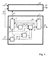
- a signal generator 5a emits predetermined signals via a line 35 during the warning by a controller 3 via a controller 5 to the converter 7, which converts and outputs the signals 37 into the warning signals 25, 55 to be emitted.
- a sensor 9 measures the immission 27, 57, which is physically equivalent to the warning signal 25, 55.
- the immission measured by the sensor 9 reaches the controller 5 and the fault value memory 11 via a line 29, the input of which is released by the control 3 through a connection 31 during the pauses in the warning - preferably only immediately before a warning - so that the fault value memory 11 only can save the warning-free fault value.
- the controller 5 is released by the controller through the connection 31 and adjusts the level of the signals 37 at its output until the measured immission 27, 57, 9, 29 of the warning signal 25, 55 is a predetermined value higher than the value of the environmental disturbance previously stored in the fault value memory 11, which value is fed to it via a line 33.
- the predetermined value can be absolute or, for example, a quotient of the two compared values, a correction value with regard to the warning signal 25, 55 for the possibly short distance between transducer 7 and sensor 9 being included.
- the controller 5 can contain the signal generator 5a or a controllable signal generator (5.5a), the connection 23 between the means 5.5a being eliminated.
- the control 3 can other, known and usual, not shown means of introduction contained in the warning and / or controlled or remotely controlled via its input 21.
- the fault value memory 11 can be, for example, a capacitor with a discharge resistor or be a digital memory.
- the means 3-11 can work analog or digital or part of a processor with its periphery.
- the sensor 9 can be a rating filter have, for example to normalize the immission value 27.57.
- the level of the warning signal must be 25.55 above that of the Environmental disturbance lie to ensure the perception of the warning signal. Nevertheless the warning signal should not be unnecessarily intense. Problems arise here in particular impermissible deviations in the transducer and sensor properties during the 7.9 Operating, for example due to pollution. In the procedure presented here however, the continuously updated emissions 27.57 of both the environmental disturbance and the Warning signal measured by the same sensor 9, so that changes in properties of the sensor 9 can be compensated. At the same time, changes in properties of the converter 7 compensated because it is included in the control loop 5,7,9.
- the level of the signals 37 at the output of the controller increases due to the compensation until it finally reaches a predetermined limit value.
- the controller 3 compares the level of the signals 37 with the predetermined limit value and, when the limit value is exceeded, causes the signal generator 5a via the line 35 to emit an interference signal.
- the warning 7,25,55 is released by the controller 3 if the interference signal is to be emitted at the output 25.55.
- the Signals 37 during the warning time via the controls 3 in the function groups 1.51 are transmitted to one another via a line 41 and compared with one another.
- Deviations in the parameters of the signals 37 such as level, duration or Frequencies beyond a predetermined level, there is a failure and the controls 3 cause a fault warning via line 35 in signal generator 5a.
- the transducers 7 can be of different physical types and for example acoustic, optical or mechanical warning signals 25.55 or a combination thereof deliver, each a pair of a transducer 7 and a sensor 9 physically are equivalent to each other.
Landscapes
- Physics & Mathematics (AREA)
- Electromagnetism (AREA)
- General Physics & Mathematics (AREA)
- Engineering & Computer Science (AREA)
- Mechanical Engineering (AREA)
- Burglar Alarm Systems (AREA)
- Train Traffic Observation, Control, And Security (AREA)
- Alarm Systems (AREA)
- Road Signs Or Road Markings (AREA)
- Measurement Of Mechanical Vibrations Or Ultrasonic Waves (AREA)
- Emergency Alarm Devices (AREA)
- Traffic Control Systems (AREA)
Claims (10)
- Procédé pour alerter des personnes - en particulier dans la zone des voies de trains - par des appareils d'alerte, qui émettent des signaux d'alerte (25, 55) dont l'intensité est supérieure à l'émission environnante physiquement équivalente en cas d'absence de génération de signaux d'alerte,caractérisé en ce quel'émission (27, 57) équivalant physiquement aux signaux d'alerte (25, 55) étant mesurée par l'appareil d'alerte pendant les pauses d'alerte et étant mémorisée comme valeur perturbatrice (11),l'émission (27, 57) des signaux d'alerte (25, 55) est mesurée par l'appareil d'alerte pendant la période d'alerte eten ce que les signaux d'alerte (37, 25, 55) sont paramétrés par l'appareil d'alerte pendant le temps d'alerte jusqu'à ce que l'émission mesurée (27, 57, 9, 29) atteigne une valeur prédéterminée supérieure à la valeur perturbatrice (27, 57, 11, 33) stockée précédemment dans les pauses d'alerte.
- Procédé selon la revendication 1, caractérisé en ce qu'une alerte de perturbation (25, 55) est déclenchée par l'appareil d'alerte si le niveau des signaux d'alerte paramétrés (37, 25, 55) dépasse une valeur limite prédéterminée.
- Procédé selon l'une des revendications précédentes, caractérisé en ce qu'une alerte de dérangement (25, 55) est déclenchée par au moins deux groupes fonctionnels similaires (1, 51) dans l'appareil d'alerte si les signaux (37) servant à donner l'alerte et comparés réciproquement divergent pendant le temps d'alerte les uns des autres au-delà d'une mesure prédéterminée.
- Procédé selon la revendication 3, caractériséen ce que les signaux (37) servant à donner l'alerte sont déclenchés par les groupes fonctionnels (1, 51) en alternative par un groupe fonctionnel respectif et sont stockés en différé eten ce que les signaux déclenchés (37) sont comparés par les groupes fonctionnels (1, 51) aux signaux mémorisés précédemment.
- Procédé selon l'une des revendications précédentes, caractérisé en ce que des signaux d'alerte (25, 55) physiquement différents sont émis par l'appareil d'alerte et leur émission (27, 57) est mesurée.
- Dispositif pour alerter des personnes - en particulier dans la zone des voies de trains - par des appareils d'alerte, qui émettent des signaux d'alerte (25, 55) dont l'intensité est supérieure à l'émission environnante physiquement équivalente en cas d'absence de génération de signaux d'alerte,caractériséun convertisseur (7) transformant des signaux, qui servent à donner l'alerte (23, 37) dans l'appareil d'alerte et qui proviennent d'un générateur de signaux (5a), en signaux d'alerte émis (25, 55)un capteur (9) mesurant l'émission (27, 57) physiquement équivalant au signal d'alerte (25, 55), et mémorisée en tant que valeur perturbatrice dans une mémoire de valeur perturbatrice (11) pendant les pauses d'alerte,en ce que l'appareil d'alerte présente une commande (3) et un régulateur (5),en ce que le capteur (9) mesure pendant le temps d'alerte (31) prédéterminé par la commande (3) l'émission (27, 57) des signaux d'alerte (25, 55) eten ce que le régulateur (5) dirige pendant le temps d'alerte (31) prédéterminé par la commande (3) les signaux issus du générateurs de signaux (5a) au convertisseur (7) et ajuste jusqu'à ce que la valeur d'émission, qui lui a été fournie par le capteur (9, 29), atteigne une valeur prédéterminée au-delà de la valeur mémorisée dans la mémoire de vapeur perturbatrice (11, 33) auparavant dans les pauses d'alerte et qui lui a été fournie par la mémoire de valeurs perturbatrices (11, 33).
- Dispositif selon la revendication 6, caractérisé en ce que la commande (3) délivre un signal de commande (35) au générateur de signaux (5a) qui génère une alerte de perturbation si le niveau des signaux fournis à la commande (3) dépasse une valeur limite prédéterminée.
- Dispositif selon l'une des revendications 6 à 7, caractériséen ce que l'appareil d'alerte présente au moins deux groupes fonctionnels similaires (1, 51) munis respectivement des moyens similaires (3-11),en ce que les commandes (3) établissent des comparaisons réciproques entre les signaux (37) pendant le temps d'alerte par l'intermédiaire d'une connexion (41) eten ce que les commandes (3) délivrent des signaux de commande (35) au générateur de signaux (5) qui génère une alerte de perturbation si les signaux comparés (37) divergent les uns des autres au-delà d'une mesure prédéterminée.
- Dispositif selon la revendication 8, caractériséen ce que lors d'une alerte, les commandes (3) libèrent les signaux (37) au convertisseur (7) en alternative dans chaque groupe fonctionnel respectif (1, 51) et les mémorisent en différé,en ce que les commandes (3) comparent les signaux libérés (37) avec les signaux mémorisés auparavant dans les commandes (3).
- Dispositif selon l'une des revendications 6 à 9, caractériséen ce que l'appareil d'alerte présente des groupes fonctionnels (1, 51) comportant des convertisseurs (7) physiquement équivalents allant par paire et des capteurs (9) eten ce que les paires (7, 9) sont de nature physiquement différente.
Applications Claiming Priority (2)
| Application Number | Priority Date | Filing Date | Title |
|---|---|---|---|
| DE19738568A DE19738568C1 (de) | 1997-09-04 | 1997-09-04 | Verfahren und Einrichtung zur Warnung von Personen |
| DE19738568 | 1997-09-04 |
Publications (3)
| Publication Number | Publication Date |
|---|---|
| EP0901111A2 EP0901111A2 (fr) | 1999-03-10 |
| EP0901111A3 EP0901111A3 (fr) | 2000-01-12 |
| EP0901111B1 true EP0901111B1 (fr) | 2003-03-26 |
Family
ID=7841103
Family Applications (1)
| Application Number | Title | Priority Date | Filing Date |
|---|---|---|---|
| EP98115790A Expired - Lifetime EP0901111B1 (fr) | 1997-09-04 | 1998-08-21 | Procédé et dispositif pour alerter des personnes |
Country Status (6)
| Country | Link |
|---|---|
| EP (1) | EP0901111B1 (fr) |
| AT (1) | ATE235728T1 (fr) |
| DE (2) | DE19738568C1 (fr) |
| DK (1) | DK0901111T3 (fr) |
| ES (1) | ES2195243T3 (fr) |
| PT (1) | PT901111E (fr) |
Families Citing this family (1)
| Publication number | Priority date | Publication date | Assignee | Title |
|---|---|---|---|---|
| GB2457307A (en) * | 2008-02-11 | 2009-08-12 | Apollo Fire Detectors Ltd | Fire alarm signalling with voice modulated HF signal multiplexed on to plateaus of existing lower frequency pulses carried on power cabling |
Family Cites Families (9)
| Publication number | Priority date | Publication date | Assignee | Title |
|---|---|---|---|---|
| US4243973A (en) * | 1979-03-27 | 1981-01-06 | Gordon B. Arnold | Home integrated signal system |
| GB2084783B (en) * | 1980-10-02 | 1985-06-19 | Production Eng Res | Audio system |
| GB2160004B (en) * | 1984-03-15 | 1988-03-30 | Patrick Joseph Lally | Improvements relating to audible warning devices |
| DE3624099A1 (de) * | 1986-07-17 | 1988-01-21 | Stein Gmbh | Einrichtung zur akustischen warnung von personen ueber einen hochfrequenten nachrichtenkanal |
| US4904992A (en) * | 1989-03-28 | 1990-02-27 | Motorola, Inc. | Radio with message reception and ambient noise level controlled indicator |
| FI90646C (fi) * | 1991-06-13 | 1994-03-10 | Kone Oy | Hissin merkinantolaitteen paikallinen automaattinen äänen voimakkuuden säätö |
| JP2972431B2 (ja) * | 1992-01-29 | 1999-11-08 | 株式会社河合楽器製作所 | 音響発生装置 |
| DE4219067A1 (de) * | 1992-06-11 | 1993-12-16 | Gerd R Dipl Ing Wetzler | Verfahren und Einrichtung zur Warnung von Personen im Gleisbereich vor herannahenden Zügen (Rottenwarnung) |
| DE4422308C2 (de) * | 1994-06-17 | 2000-01-13 | Zoellner Gmbh | Automatisches Rottenwarngerät |
-
1997
- 1997-09-04 DE DE19738568A patent/DE19738568C1/de not_active Expired - Fee Related
-
1998
- 1998-08-21 PT PT98115790T patent/PT901111E/pt unknown
- 1998-08-21 AT AT98115790T patent/ATE235728T1/de not_active IP Right Cessation
- 1998-08-21 EP EP98115790A patent/EP0901111B1/fr not_active Expired - Lifetime
- 1998-08-21 DK DK98115790T patent/DK0901111T3/da active
- 1998-08-21 ES ES98115790T patent/ES2195243T3/es not_active Expired - Lifetime
- 1998-08-21 DE DE59807622T patent/DE59807622D1/de not_active Expired - Fee Related
Also Published As
| Publication number | Publication date |
|---|---|
| ES2195243T3 (es) | 2003-12-01 |
| EP0901111A2 (fr) | 1999-03-10 |
| EP0901111A3 (fr) | 2000-01-12 |
| DE59807622D1 (de) | 2003-04-30 |
| DK0901111T3 (da) | 2003-06-16 |
| PT901111E (pt) | 2003-08-29 |
| DE19738568C1 (de) | 1999-03-11 |
| ATE235728T1 (de) | 2003-04-15 |
Similar Documents
| Publication | Publication Date | Title |
|---|---|---|
| DE3415786C3 (de) | Rechnergesteuertes Feueralarmsystem | |
| DE3142555C2 (fr) | ||
| DE2445122C2 (de) | Wächterschaltung für eine Einrichtung zur Überwachung der Wellenspannung von elektrischen Maschinen | |
| DE3137910C2 (de) | Automatikgetriebesteuereinrichtung mit Sicherheitsschaltung | |
| DE102018003744A1 (de) | Akustisches Zustandsüberwachungsverfahren und -system für elektrische Leistungskomponenten, insbesondere Transformatoren | |
| CH637597A5 (de) | Vorrichtung zum steuern der drehzahl eines wickelorgans einer fadenspeicher- und -liefervorrichtung. | |
| EP0325903A2 (fr) | Circuit amplificateur de charge | |
| DE3415766C2 (fr) | ||
| EP0955522A1 (fr) | Méthode et circuit pour vérifier l'entrefer d'un capteur tachymétrique | |
| DE2638068B2 (de) | Brandmeldeanlage mit mehreren über eine Meldeschleife betreibbaren Meldern | |
| DE3347459A1 (de) | Anordnung zur ueberwachung des betriebs von eingabeschaltungen einer zentraleinheit zum steuern und ueberwachen von in fertigungs- und/oder verpackungsfliessbaendern einsetzbaren maschinen und/oder geraeten | |
| EP0042501A1 (fr) | Dispositif pour la transmission des valeurs mesurées dans un système d'avertissement d'incendie | |
| DE2631569C2 (de) | Schaltungsanordnung zum Überprüfen der Funktionsfähigkeit von Teilen einer blockiergeschützten Fahrzeugbremsanlage | |
| DE2903809A1 (de) | Ueberwachungs- und anzeigeschaltung | |
| EP0358887B1 (fr) | Circuit de détection d'erreur dans un appareil de mesure | |
| DE3218541C1 (de) | Schienenkontakt für spurgeführte Fahrzeuge | |
| EP0545026B1 (fr) | Système de commande automatique sûre de la distance mutuelle de véhicules. | |
| DE3701714A1 (de) | Verfahren und vorrichtung zur ueberwachung rechnergesteuerter stellglieder | |
| DE4228112C1 (en) | Object detection arrangement - contains light source and receiver, comparator with comparison voltages controlled by micro-controller | |
| DE19738568C1 (de) | Verfahren und Einrichtung zur Warnung von Personen | |
| DE4244761C2 (de) | Füllstand-Grenzschalter | |
| EP1197936B1 (fr) | Système d'alarme | |
| EP0687614A1 (fr) | Dispositif d'alarme automatique pour les ouvriers au chemin de fer | |
| DE2704548C2 (de) | Sicherheitsanordnung für folgemäßig oder abschnittweise verkehrende, spurgeführte Fahrzeuge | |
| DE2834805C2 (de) | Schaltung zur Überwachung einer Gleichspannung gegenüber einer Referenzspannung innerhalb einstellbarer Toleranzgrenzen |
Legal Events
| Date | Code | Title | Description |
|---|---|---|---|
| PUAI | Public reference made under article 153(3) epc to a published international application that has entered the european phase |
Free format text: ORIGINAL CODE: 0009012 |
|
| AK | Designated contracting states |
Kind code of ref document: A2 Designated state(s): AT BE CH DE DK ES FR GB IT LI NL PT SE |
|
| AX | Request for extension of the european patent |
Free format text: AL;LT;LV;MK;RO;SI |
|
| PUAL | Search report despatched |
Free format text: ORIGINAL CODE: 0009013 |
|
| AK | Designated contracting states |
Kind code of ref document: A3 Designated state(s): AT BE CH CY DE DK ES FI FR GB GR IE IT LI LU MC NL PT SE |
|
| AX | Request for extension of the european patent |
Free format text: AL;LT;LV;MK;RO;SI |
|
| 17P | Request for examination filed |
Effective date: 20000614 |
|
| AKX | Designation fees paid |
Free format text: AT BE CH DE DK ES FR GB IT LI NL PT SE |
|
| RAP1 | Party data changed (applicant data changed or rights of an application transferred) |
Owner name: STEIN, HERMANN |
|
| RIN1 | Information on inventor provided before grant (corrected) |
Inventor name: STEIN, HERMANN |
|
| RAP1 | Party data changed (applicant data changed or rights of an application transferred) |
Owner name: SCHWEIZER ELECTRONIC M2S AG |
|
| RIN1 | Information on inventor provided before grant (corrected) |
Inventor name: SCHWEIZER ELECTRONIC M2S AG |
|
| GRAH | Despatch of communication of intention to grant a patent |
Free format text: ORIGINAL CODE: EPIDOS IGRA |
|
| GRAH | Despatch of communication of intention to grant a patent |
Free format text: ORIGINAL CODE: EPIDOS IGRA |
|
| GRAA | (expected) grant |
Free format text: ORIGINAL CODE: 0009210 |
|
| RIN1 | Information on inventor provided before grant (corrected) |
Inventor name: STEIN, HERMANN |
|
| AK | Designated contracting states |
Designated state(s): AT BE CH DE DK ES FR GB IT LI NL PT SE |
|
| REG | Reference to a national code |
Ref country code: GB Ref legal event code: FG4D Free format text: NOT ENGLISH |
|
| REG | Reference to a national code |
Ref country code: CH Ref legal event code: NV Representative=s name: BOVARD AG PATENTANWAELTE Ref country code: CH Ref legal event code: EP |
|
| REF | Corresponds to: |
Ref document number: 59807622 Country of ref document: DE Date of ref document: 20030430 Kind code of ref document: P |
|
| REG | Reference to a national code |
Ref country code: DK Ref legal event code: T3 |
|
| REG | Reference to a national code |
Ref country code: SE Ref legal event code: TRGR |
|
| GBT | Gb: translation of ep patent filed (gb section 77(6)(a)/1977) | ||
| ET | Fr: translation filed | ||
| PLBE | No opposition filed within time limit |
Free format text: ORIGINAL CODE: 0009261 |
|
| STAA | Information on the status of an ep patent application or granted ep patent |
Free format text: STATUS: NO OPPOSITION FILED WITHIN TIME LIMIT |
|
| 26N | No opposition filed |
Effective date: 20031230 |
|
| PGFP | Annual fee paid to national office [announced via postgrant information from national office to epo] |
Ref country code: AT Payment date: 20040706 Year of fee payment: 7 |
|
| PGFP | Annual fee paid to national office [announced via postgrant information from national office to epo] |
Ref country code: FR Payment date: 20040708 Year of fee payment: 7 |
|
| PGFP | Annual fee paid to national office [announced via postgrant information from national office to epo] |
Ref country code: DK Payment date: 20040709 Year of fee payment: 7 |
|
| PGFP | Annual fee paid to national office [announced via postgrant information from national office to epo] |
Ref country code: GB Payment date: 20040712 Year of fee payment: 7 |
|
| PGFP | Annual fee paid to national office [announced via postgrant information from national office to epo] |
Ref country code: NL Payment date: 20040714 Year of fee payment: 7 |
|
| PGFP | Annual fee paid to national office [announced via postgrant information from national office to epo] |
Ref country code: PT Payment date: 20040715 Year of fee payment: 7 |
|
| PGFP | Annual fee paid to national office [announced via postgrant information from national office to epo] |
Ref country code: DE Payment date: 20040716 Year of fee payment: 7 |
|
| PGFP | Annual fee paid to national office [announced via postgrant information from national office to epo] |
Ref country code: SE Payment date: 20040719 Year of fee payment: 7 |
|
| PGFP | Annual fee paid to national office [announced via postgrant information from national office to epo] |
Ref country code: ES Payment date: 20040804 Year of fee payment: 7 Ref country code: BE Payment date: 20040804 Year of fee payment: 7 |
|
| PGFP | Annual fee paid to national office [announced via postgrant information from national office to epo] |
Ref country code: CH Payment date: 20040811 Year of fee payment: 7 |
|
| PG25 | Lapsed in a contracting state [announced via postgrant information from national office to epo] |
Ref country code: IT Free format text: LAPSE BECAUSE OF NON-PAYMENT OF DUE FEES;WARNING: LAPSES OF ITALIAN PATENTS WITH EFFECTIVE DATE BEFORE 2007 MAY HAVE OCCURRED AT ANY TIME BEFORE 2007. THE CORRECT EFFECTIVE DATE MAY BE DIFFERENT FROM THE ONE RECORDED. Effective date: 20050821 Ref country code: GB Free format text: LAPSE BECAUSE OF NON-PAYMENT OF DUE FEES Effective date: 20050821 Ref country code: AT Free format text: LAPSE BECAUSE OF NON-PAYMENT OF DUE FEES Effective date: 20050821 |
|
| PG25 | Lapsed in a contracting state [announced via postgrant information from national office to epo] |
Ref country code: SE Free format text: LAPSE BECAUSE OF NON-PAYMENT OF DUE FEES Effective date: 20050822 Ref country code: ES Free format text: LAPSE BECAUSE OF NON-PAYMENT OF DUE FEES Effective date: 20050822 |
|
| PG25 | Lapsed in a contracting state [announced via postgrant information from national office to epo] |
Ref country code: LI Free format text: LAPSE BECAUSE OF NON-PAYMENT OF DUE FEES Effective date: 20050831 Ref country code: DK Free format text: LAPSE BECAUSE OF NON-PAYMENT OF DUE FEES Effective date: 20050831 Ref country code: CH Free format text: LAPSE BECAUSE OF NON-PAYMENT OF DUE FEES Effective date: 20050831 Ref country code: BE Free format text: LAPSE BECAUSE OF NON-PAYMENT OF DUE FEES Effective date: 20050831 |
|
| PG25 | Lapsed in a contracting state [announced via postgrant information from national office to epo] |
Ref country code: PT Free format text: LAPSE BECAUSE OF NON-PAYMENT OF DUE FEES Effective date: 20060221 |
|
| PG25 | Lapsed in a contracting state [announced via postgrant information from national office to epo] |
Ref country code: NL Free format text: LAPSE BECAUSE OF NON-PAYMENT OF DUE FEES Effective date: 20060301 Ref country code: DE Free format text: LAPSE BECAUSE OF NON-PAYMENT OF DUE FEES Effective date: 20060301 |
|
| REG | Reference to a national code |
Ref country code: CH Ref legal event code: PL |
|
| REG | Reference to a national code |
Ref country code: DK Ref legal event code: EBP |
|
| EUG | Se: european patent has lapsed | ||
| GBPC | Gb: european patent ceased through non-payment of renewal fee |
Effective date: 20050821 |
|
| PG25 | Lapsed in a contracting state [announced via postgrant information from national office to epo] |
Ref country code: FR Free format text: LAPSE BECAUSE OF NON-PAYMENT OF DUE FEES Effective date: 20060428 |
|
| NLV4 | Nl: lapsed or anulled due to non-payment of the annual fee |
Effective date: 20060301 |
|
| REG | Reference to a national code |
Ref country code: FR Ref legal event code: ST Effective date: 20060428 |
|
| REG | Reference to a national code |
Ref country code: ES Ref legal event code: FD2A Effective date: 20050822 |
|
| BERE | Be: lapsed |
Owner name: *SCHWEIZER ELECTRONIC M2S A.G. Effective date: 20050831 |