EP0901202A2 - Lampe électrique avec réflecteur - Google Patents
Lampe électrique avec réflecteur Download PDFInfo
- Publication number
- EP0901202A2 EP0901202A2 EP98116606A EP98116606A EP0901202A2 EP 0901202 A2 EP0901202 A2 EP 0901202A2 EP 98116606 A EP98116606 A EP 98116606A EP 98116606 A EP98116606 A EP 98116606A EP 0901202 A2 EP0901202 A2 EP 0901202A2
- Authority
- EP
- European Patent Office
- Prior art keywords
- reflector
- lamp
- lamp holder
- receptacle
- holder
- Prior art date
- Legal status (The legal status is an assumption and is not a legal conclusion. Google has not performed a legal analysis and makes no representation as to the accuracy of the status listed.)
- Granted
Links
- 238000000034 method Methods 0.000 claims abstract description 8
- 229920003023 plastic Polymers 0.000 claims abstract description 6
- 239000004033 plastic Substances 0.000 claims abstract description 6
- 230000015572 biosynthetic process Effects 0.000 claims description 4
- 238000005755 formation reaction Methods 0.000 claims description 4
- 239000000463 material Substances 0.000 claims description 3
- 238000006073 displacement reaction Methods 0.000 description 3
- 239000004697 Polyetherimide Substances 0.000 description 2
- 229920001601 polyetherimide Polymers 0.000 description 2
- 239000003292 glue Substances 0.000 description 1
- 230000005855 radiation Effects 0.000 description 1
- 239000007787 solid Substances 0.000 description 1
- 238000003466 welding Methods 0.000 description 1
Images


Classifications
-
- F—MECHANICAL ENGINEERING; LIGHTING; HEATING; WEAPONS; BLASTING
- F21—LIGHTING
- F21V—FUNCTIONAL FEATURES OR DETAILS OF LIGHTING DEVICES OR SYSTEMS THEREOF; STRUCTURAL COMBINATIONS OF LIGHTING DEVICES WITH OTHER ARTICLES, NOT OTHERWISE PROVIDED FOR
- F21V19/00—Fastening of light sources or lamp holders
- F21V19/02—Fastening of light sources or lamp holders with provision for adjustment, e.g. for focusing
Definitions
- the invention relates to a reflector lamp consisting of a reflector and a lamp holder with lamp, in which the Lamp holder fixed with one on the back of the reflector arranged recording is connected.
- the invention further relates to a method for solid Connect a lamp holder with lamp to one on the Back of a reflector arranged receptacle.
- a reflector lamp which a reflector with a receptacle for a lamp housing has its back. With a pre-focused lamp The lamp housing is provided from the rear of the reflector used in its recording and by Ultrasonic welding firmly connected to the holder. Possible tolerances of the reflector can be practical not be balanced. One is in particular Longitudinal displacement of the lamp holder in the holder of the Reflector not possible.
- the object of the present invention is therefore a fixed Connection between lamp holder and reflector or its To create recording where the lamp with your Lamp holder is focusable in the focal point of the reflector.
- the Lamp holder on one inside of the holder facing outside at least one lug has that transverse to a longitudinal axis of the lamp holder is arranged and in a groove of the receptacle is guided longitudinally and by plastic Deformation can be positively connected to the receptacle.
- the connecting block is longitudinally displaceable in the Is guided groove, the lamp or its filament can simple longitudinal displacement of the lamp holder in the focal point of the Be focused reflector.
- the lampholder is fixed to the guide bracket with the reflector or its inclusion connectable.
- the Lamp holder two opposite each other Lugs on their lamp holder opposite ends over the wall of the grooves Protruding recording.
- the grooves are on each other opposite inner surfaces with tooth-like formations provided at least partially by the material of the plastically deformed ends of the lugs can be filled are.
- Through the two opposite one another Lugs will load evenly plastic deformation achieved.
- Through the tooth-like Forming the groove becomes a positive connection achieved after the plastic deformation of the Lugs a longitudinal displacement of the lamp holder reliably prevented.
- Another object of the invention is therefore a method for to create a firm connection between lamp holder and reflector, that allows adjustment of the lamp holder in the reflector.
- the object is achieved in that the Lamp holder with lamp in the reflector is adjusted and connecting blocks arranged on the side of the lamp holder, which are guided longitudinally in the grooves of the receptacle, positively connected to the mount of the reflector become.
- the free ends facing away from the recording are moved the lugs are deformed by hot stamping.
- Hot stamping makes it particularly quick and safe Achieve connection between lamp housing and reflector.
- the Filament of the lamp with respect to the longitudinal axis of the reflector by moving the lamp holder in the longitudinal direction in Focus of the reflector using an adjustment device focused.
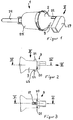
- a reflector lamp (1) consists essentially of one Reflector (2), a lamp holder (3) and a lamp (4).
- the reflector (2) can be used, for example, as an ellipsoid reflector be formed by the one in its focus (5) located filament (6) of the lamp (4) outgoing light focused a second focus, not shown.
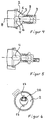
- the receptacle (9) has one Receiving opening (10) into which from the rear (7) Lamp holder (3) with lamp (4) can be inserted.
- the The receptacle (9) faces away from the reflector (2) free end of an end face (11).
- the receptacle (9) points on its wall (12) surrounding the receiving opening (10) two mutually opposite grooves (13).
- the slit-shaped formed grooves (13) are towards the end face (11) open.
- the wall (12) towards the longitudinal axis (8) an inside (14) and on the inside (14) facing away from an outer side (15).
- the groove (13) has two mutually opposite inner surfaces (16) on that in a region facing the inside (14) as plane-parallel guide surfaces (17) are formed.
- In one the area adjacent to the outside (15) is the inside surfaces (16) with tooth-like formations (18).
- the receiving opening (10) or the inside (14) of the recording (9) is flared to the end face (11) by about 3 °. This makes it possible to mount the lamp (3) Tilt the reflector (2) for adjustment purposes.
- the recording (9) has four on its inside (14) in the longitudinal direction Guide bars (19).
- the lamp holder (3) points to the holder (9) facing side an approach (20), which in the Receiving opening (10) of the reflector (2) can be inserted.
- the projection (20) On its the inside (14) facing the receptacle (9) Outside (21), the projection (20) has two against each other opposite lugs (22) in the groove (13) of the wall (12) can be moved longitudinally.
- the Lugs (22) protrude with their approach (20)
- Lamp holder (3) facing away from free ends (23) Outside (15) of the wall (12) also.
- the Lugs (22) are transverse to the longitudinal axis (8) arranged.
- the location of a not shown Socket pin holder is at a defined distance to the lugs (22) to the location of the filament (6) to be reproducible.
- the reflector lamp (1) can, for example, be used for mirroring of light can be used in a light guide (24).
- the light guide (24) is connected to the via a holder (25) Connectable reflector (2).
- Lamp socket (3) At its end facing away from the reflector (2) Lamp socket (3) has a connection (26) on the one Mains plug (27) can be plugged on.
- the lamp holder (3) is from the back (7) forth in the receiving opening (10) of the receptacle (9), so that the connecting blocks (22) from the guide surfaces (17) are performed.
- the filament (6) of the lamp (4) is with Using an adjusting device, not shown, for measuring the focusing and moving the filament with respect to the Longitudinal axis (8) in the focal point (5) of the reflector (2) through Move the lamp holder (3) and if necessary Tilting focused.
- the free ends (23) of the Connecting block (22) plastically deformed by hot stamping, so that the material of the free ends (23) at least partially fills the tooth-like formations (18) of the grooves (13) and a positive connection between the receptacle (9) and Lamp socket (3) or the connecting block (22) is created.
- the connecting blocks (22) can be made, for example Polyetherimide (PEI) can be formed.
- PEI Polyetherimide
Landscapes
- Engineering & Computer Science (AREA)
- General Engineering & Computer Science (AREA)
- Fastening Of Light Sources Or Lamp Holders (AREA)
- Non-Portable Lighting Devices Or Systems Thereof (AREA)
Applications Claiming Priority (2)
| Application Number | Priority Date | Filing Date | Title |
|---|---|---|---|
| DE19739022A DE19739022A1 (de) | 1997-09-06 | 1997-09-06 | Reflektorleuchte |
| DE19739022 | 1997-09-06 |
Publications (3)
| Publication Number | Publication Date |
|---|---|
| EP0901202A2 true EP0901202A2 (fr) | 1999-03-10 |
| EP0901202A3 EP0901202A3 (fr) | 1999-12-08 |
| EP0901202B1 EP0901202B1 (fr) | 2006-07-26 |
Family
ID=7841410
Family Applications (1)
| Application Number | Title | Priority Date | Filing Date |
|---|---|---|---|
| EP98116606A Expired - Lifetime EP0901202B1 (fr) | 1997-09-06 | 1998-09-02 | Lampe électrique avec réflecteur |
Country Status (4)
| Country | Link |
|---|---|
| US (1) | US6158880A (fr) |
| EP (1) | EP0901202B1 (fr) |
| AT (1) | ATE334491T1 (fr) |
| DE (2) | DE19739022A1 (fr) |
Cited By (1)
| Publication number | Priority date | Publication date | Assignee | Title |
|---|---|---|---|---|
| EP1892466A1 (fr) * | 2006-08-21 | 2008-02-27 | C & G Carandini, S.A. | Support pour une source lumineuse |
Family Cites Families (13)
| Publication number | Priority date | Publication date | Assignee | Title |
|---|---|---|---|---|
| US4219870A (en) * | 1978-07-07 | 1980-08-26 | Gte Sylvania Incorporated | Front loading projection unit |
| US4282565A (en) * | 1979-07-16 | 1981-08-04 | General Electric Company | Sealed, prefocused mount for plastic PAR lamp |
| US4376967A (en) * | 1980-12-03 | 1983-03-15 | Gte Products Corporation | Front loading projection unit with wireform retention member |
| DE3101640A1 (de) * | 1981-01-20 | 1982-08-26 | Patent-Treuhand-Gesellschaft für elektrische Glühlampen mbH, 8000 München | Sealed beam-scheinwerfer |
| FR2604132B1 (fr) * | 1986-09-18 | 1990-04-20 | Cibie Projecteurs | Dispositif de fixation pour lampe de vehicule automobile |
| US4820956A (en) * | 1987-10-02 | 1989-04-11 | Integrated Systems Engineering, Inc. | Light matrix display system |
| EP0367323B1 (fr) * | 1988-10-18 | 1994-07-27 | Koninklijke Philips Electronics N.V. | Unité lampe-réflecteur |
| US5010455A (en) * | 1990-05-07 | 1991-04-23 | General Motors Corporation | Headlamp assembly |
| DE4317491A1 (de) * | 1993-05-26 | 1994-12-01 | Abb Patent Gmbh | Glimmlampe zum Einstecken |
| DE4428357A1 (de) * | 1994-08-10 | 1996-02-15 | Patent Treuhand Ges Fuer Elektrische Gluehlampen Mbh | Kittlos gesockelte Halogenglühlampe |
| JP3423494B2 (ja) * | 1995-07-25 | 2003-07-07 | 株式会社ニフコ | 留め具 |
| DE19548521A1 (de) * | 1995-12-22 | 1997-06-26 | Patent Treuhand Ges Fuer Elektrische Gluehlampen Mbh | Lampen-Reflektor-Einheit |
| JPH09245503A (ja) * | 1996-03-07 | 1997-09-19 | Koito Mfg Co Ltd | 灯具のバルブ固定構造 |
-
1997
- 1997-09-06 DE DE19739022A patent/DE19739022A1/de not_active Withdrawn
-
1998
- 1998-08-28 US US09/143,532 patent/US6158880A/en not_active Expired - Fee Related
- 1998-09-02 AT AT98116606T patent/ATE334491T1/de not_active IP Right Cessation
- 1998-09-02 EP EP98116606A patent/EP0901202B1/fr not_active Expired - Lifetime
- 1998-09-02 DE DE59813657T patent/DE59813657D1/de not_active Expired - Lifetime
Cited By (1)
| Publication number | Priority date | Publication date | Assignee | Title |
|---|---|---|---|---|
| EP1892466A1 (fr) * | 2006-08-21 | 2008-02-27 | C & G Carandini, S.A. | Support pour une source lumineuse |
Also Published As
| Publication number | Publication date |
|---|---|
| ATE334491T1 (de) | 2006-08-15 |
| US6158880A (en) | 2000-12-12 |
| DE59813657D1 (de) | 2006-09-07 |
| DE19739022A1 (de) | 1999-03-11 |
| EP0901202A3 (fr) | 1999-12-08 |
| EP0901202B1 (fr) | 2006-07-26 |
Similar Documents
| Publication | Publication Date | Title |
|---|---|---|
| DE4021434C2 (fr) | ||
| EP0570652B1 (fr) | Connecteur pour fibres optiques | |
| EP0599784A1 (fr) | Douille pour un terminal de connexion à fibre optique | |
| DE19849026A1 (de) | Verfahren zum Befestigen eines Lichtleitfaserendes in einer Kunststoffkontakthülse und entsprechend hergestellter Kunststoffkontakt | |
| EP1860473A1 (fr) | Connecteur optique muni d'un élément de maintien verrouillable et longitudinalement déplacable dans un élément support | |
| EP1478959A1 (fr) | Raccord optique enfichable | |
| EP0305832A2 (fr) | Raccordement à fiches pour des guides d'ondes lumineuses | |
| EP3317581B1 (fr) | Dispositif d'éclairage pour un phare de véhicule | |
| DE19948372C2 (de) | Faseroptisches Sende-Bauelement mit präzise einstellbarer Einkopplung | |
| EP3856568A1 (fr) | Raccord de dilatation pour une ligne de contact et ligne de contact | |
| DE19950189B4 (de) | Stellantrieb, insbesondere zum Antrieb eines Kfz-Rückblickspiegels | |
| DE9214524U1 (de) | Elektrische Lampenfassung aus Kunststoff | |
| EP0901202A2 (fr) | Lampe électrique avec réflecteur | |
| WO2000014582A2 (fr) | Embout pour fibres optiques | |
| AT523583A2 (de) | Schienenleuchtensystem | |
| WO2016041637A1 (fr) | Endoscope et procédé de montage d'une optique d'un endoscope | |
| DE2838011A1 (de) | Stromschiene | |
| DE10219170B4 (de) | Fahrzeugleuchte | |
| DE10131273C1 (de) | Lichtwellenleiter-(LWL)-Steckverbinderanordnung | |
| DE10019830A1 (de) | Lichtemissions- und Lichtaufnahmevorrichtung | |
| DE19920427B4 (de) | Vorrichtung zum Verbinden von Rohren in unterschiedlichen Winkelstellungen | |
| DE19624724A1 (de) | Filtereinheit für einen Verbinder zu einer Entladungslampe, insbesondere in einem Kraftfahrzeugscheinwerfer, Baugruppe aus einem Verbinder und einer solchen Fitereinheit, und Scheinwerfer mit einer solchen Baugruppe | |
| DE3832399A1 (de) | Rohrhalter und verfahren zur rohrmontage mittels eines rohrhalters | |
| DE29512773U1 (de) | Halterung für die Befestigung eines optischen Moduls, insbesondere eines Buchsenteils für einen optischen Steckverbinder auf einer Platine | |
| DE29707632U1 (de) | Halterung |
Legal Events
| Date | Code | Title | Description |
|---|---|---|---|
| PUAI | Public reference made under article 153(3) epc to a published international application that has entered the european phase |
Free format text: ORIGINAL CODE: 0009012 |
|
| AK | Designated contracting states |
Kind code of ref document: A2 Designated state(s): AT DE ES FR GB IT |
|
| AX | Request for extension of the european patent |
Free format text: AL;LT;LV;MK;RO;SI |
|
| 17P | Request for examination filed |
Effective date: 19990707 |
|
| PUAL | Search report despatched |
Free format text: ORIGINAL CODE: 0009013 |
|
| AK | Designated contracting states |
Kind code of ref document: A3 Designated state(s): AT BE CH CY DE DK ES FI FR GB GR IE IT LI LU MC NL PT SE |
|
| AX | Request for extension of the european patent |
Free format text: AL;LT;LV;MK;RO;SI |
|
| RIC1 | Information provided on ipc code assigned before grant |
Free format text: 6H 01R 33/05 A, 6F 21M 7/00 B |
|
| D17P | Request for examination filed (deleted) | ||
| R17P | Request for examination filed (corrected) |
Effective date: 20000313 |
|
| AKX | Designation fees paid |
Free format text: AT DE ES FR GB IT |
|
| RAP1 | Party data changed (applicant data changed or rights of an application transferred) |
Owner name: HELLA KGAA HUECK & CO. |
|
| GRAP | Despatch of communication of intention to grant a patent |
Free format text: ORIGINAL CODE: EPIDOSNIGR1 |
|
| RIC1 | Information provided on ipc code assigned before grant |
Ipc: F21V 7/00 20060101ALI20060223BHEP Ipc: H01R 33/05 20060101AFI20060223BHEP |
|
| GRAS | Grant fee paid |
Free format text: ORIGINAL CODE: EPIDOSNIGR3 |
|
| GRAA | (expected) grant |
Free format text: ORIGINAL CODE: 0009210 |
|
| AK | Designated contracting states |
Kind code of ref document: B1 Designated state(s): AT DE ES FR GB IT |
|
| PG25 | Lapsed in a contracting state [announced via postgrant information from national office to epo] |
Ref country code: GB Free format text: LAPSE BECAUSE OF FAILURE TO SUBMIT A TRANSLATION OF THE DESCRIPTION OR TO PAY THE FEE WITHIN THE PRESCRIBED TIME-LIMIT Effective date: 20060726 |
|
| REG | Reference to a national code |
Ref country code: GB Ref legal event code: FG4D Free format text: NOT ENGLISH |
|
| REF | Corresponds to: |
Ref document number: 59813657 Country of ref document: DE Date of ref document: 20060907 Kind code of ref document: P |
|
| PGFP | Annual fee paid to national office [announced via postgrant information from national office to epo] |
Ref country code: IT Payment date: 20060930 Year of fee payment: 9 |
|
| PG25 | Lapsed in a contracting state [announced via postgrant information from national office to epo] |
Ref country code: ES Free format text: LAPSE BECAUSE OF FAILURE TO SUBMIT A TRANSLATION OF THE DESCRIPTION OR TO PAY THE FEE WITHIN THE PRESCRIBED TIME-LIMIT Effective date: 20061106 |
|
| GBV | Gb: ep patent (uk) treated as always having been void in accordance with gb section 77(7)/1977 [no translation filed] |
Effective date: 20060726 |
|
| ET | Fr: translation filed | ||
| PLBE | No opposition filed within time limit |
Free format text: ORIGINAL CODE: 0009261 |
|
| STAA | Information on the status of an ep patent application or granted ep patent |
Free format text: STATUS: NO OPPOSITION FILED WITHIN TIME LIMIT |
|
| 26N | No opposition filed |
Effective date: 20070427 |
|
| PG25 | Lapsed in a contracting state [announced via postgrant information from national office to epo] |
Ref country code: AT Free format text: LAPSE BECAUSE OF NON-PAYMENT OF DUE FEES Effective date: 20060902 |
|
| PG25 | Lapsed in a contracting state [announced via postgrant information from national office to epo] |
Ref country code: IT Free format text: LAPSE BECAUSE OF NON-PAYMENT OF DUE FEES Effective date: 20070902 |
|
| PGFP | Annual fee paid to national office [announced via postgrant information from national office to epo] |
Ref country code: DE Payment date: 20090827 Year of fee payment: 12 |
|
| PGFP | Annual fee paid to national office [announced via postgrant information from national office to epo] |
Ref country code: FR Payment date: 20091012 Year of fee payment: 12 |
|
| REG | Reference to a national code |
Ref country code: FR Ref legal event code: ST Effective date: 20110531 |
|
| REG | Reference to a national code |
Ref country code: DE Ref legal event code: R119 Ref document number: 59813657 Country of ref document: DE Effective date: 20110401 |
|
| PG25 | Lapsed in a contracting state [announced via postgrant information from national office to epo] |
Ref country code: FR Free format text: LAPSE BECAUSE OF NON-PAYMENT OF DUE FEES Effective date: 20100930 Ref country code: DE Free format text: LAPSE BECAUSE OF NON-PAYMENT OF DUE FEES Effective date: 20110401 |