EP0901310A2 - Dispositif pour afficher un état de chauffe - Google Patents
Dispositif pour afficher un état de chauffe Download PDFInfo
- Publication number
- EP0901310A2 EP0901310A2 EP98890213A EP98890213A EP0901310A2 EP 0901310 A2 EP0901310 A2 EP 0901310A2 EP 98890213 A EP98890213 A EP 98890213A EP 98890213 A EP98890213 A EP 98890213A EP 0901310 A2 EP0901310 A2 EP 0901310A2
- Authority
- EP
- European Patent Office
- Prior art keywords
- rod
- switch head
- tube
- head
- switch
- Prior art date
- Legal status (The legal status is an assumption and is not a legal conclusion. Google has not performed a legal analysis and makes no representation as to the accuracy of the status listed.)
- Withdrawn
Links
Images

Classifications
-
- H—ELECTRICITY
- H05—ELECTRIC TECHNIQUES NOT OTHERWISE PROVIDED FOR
- H05B—ELECTRIC HEATING; ELECTRIC LIGHT SOURCES NOT OTHERWISE PROVIDED FOR; CIRCUIT ARRANGEMENTS FOR ELECTRIC LIGHT SOURCES, IN GENERAL
- H05B1/00—Details of electric heating devices
- H05B1/02—Automatic switching arrangements specially adapted to apparatus ; Control of heating devices
- H05B1/0202—Switches
- H05B1/0216—Switches actuated by the expansion of a solid element, e.g. wire or rod
-
- G—PHYSICS
- G01—MEASURING; TESTING
- G01K—MEASURING TEMPERATURE; MEASURING QUANTITY OF HEAT; THERMALLY-SENSITIVE ELEMENTS NOT OTHERWISE PROVIDED FOR
- G01K5/00—Measuring temperature based on the expansion or contraction of a material
- G01K5/48—Measuring temperature based on the expansion or contraction of a material the material being a solid
-
- H—ELECTRICITY
- H01—ELECTRIC ELEMENTS
- H01H—ELECTRIC SWITCHES; RELAYS; SELECTORS; EMERGENCY PROTECTIVE DEVICES
- H01H37/00—Thermally-actuated switches
- H01H37/02—Details
- H01H37/32—Thermally-sensitive members
- H01H37/46—Thermally-sensitive members actuated due to expansion or contraction of a solid
- H01H37/48—Thermally-sensitive members actuated due to expansion or contraction of a solid with extensible rigid rods or tubes
-
- H—ELECTRICITY
- H05—ELECTRIC TECHNIQUES NOT OTHERWISE PROVIDED FOR
- H05B—ELECTRIC HEATING; ELECTRIC LIGHT SOURCES NOT OTHERWISE PROVIDED FOR; CIRCUIT ARRANGEMENTS FOR ELECTRIC LIGHT SOURCES, IN GENERAL
- H05B3/00—Ohmic-resistance heating
- H05B3/68—Heating arrangements specially adapted for cooking plates or analogous hot-plates
- H05B3/74—Non-metallic plates, e.g. vitroceramic, ceramic or glassceramic hobs, also including power or control circuits
- H05B3/746—Protection, e.g. overheat cutoff, hot plate indicator
Definitions
- the invention relates to a device for hot display in a temperature controller comprising a temperature sensor with a rod guided in a tube, the Coefficient of thermal expansion is different from that of the pipe and one at the first End of the temperature sensor arranged switch head, the tube with its switch head side End held immobile in relation to the switch head and the rod with his switch head end protruding into the switch head and movable relative to this is held and the tube and rod at their ends facing away from the switch head immovable are held to each other.
- Electric cooking appliances with radiant or contact radiators have the disadvantage that that the cooking surface after switching off the heating current until it cools down completely takes a relatively long time, so that there is a risk of touching the Burn the hob.
- This danger occurs especially in those cooking appliances where one or more radiators through a metal plate covering all radiators, one Glass ceramic plate with a very low coefficient of thermal expansion or the like. are covered, through which a cooktop is created that has a continuous level Represents surface of the hob.
- This cooking surface appears like the surface of a table top Appearance without it being apparent whether a touch without risk of burns is possible.
- the radiators arranged below the cooking surface can be contact radiators or radiant heaters, the latter radiators without a metallic protective layer represent the heat conductor, in which the heat is predominantly radiated to the cooking zone is delivered.
- step on the cooking surface Depending on the heating of the individual radiators, zones at different temperatures. Becomes If a radiator is heated, the cooking zone assigned to it has a high temperature on, whereas the cooking zones of the unheated radiators have a low temperature own, can be touched without risk of burn, what for the cooking zone of the heated radiator is not the case. But this is generally not the case with the hob recognizable.
- the temperature in the radiation area of the radiator is 700 ° C. A however, safe contact is only possible at temperatures below 60 ° C.
- a temperature sensor between the same and the cooking surface, which consists of a There is a tube with an internal rod, the tube and rod being different from one another Have coefficients of thermal expansion.
- a switch head with contact system is provided at the first end of the temperature sensor.
- the tube is with its switch head facing end fixed on this switch head, the end of the rod is in the switch head protruding and kept free relative to this switch head. Because of that comes it when the temperature sensor is heated to an axial relative movement of the end of the rod on the switch head side relative to the tube or relative to the switch head, which is used to operate a contact system, via which contact system the Radiator is supplied with voltage.
- Hot display To warn against touching a hot area of the cooking surface
- Devices for so-called hot display become known, which in the switch head of a temperature controller just explained are arranged. They include a switch contact that is connected to a signal device and also with temperature-related shift the switch head end of the rod is actuated.
- This hot display is like this designed that the switching contact at temperatures of the cooking surface, for example above of 60 ° C, is operated so that the signaling device indicates that a touch the cooking surface carries the risk of burns.
- This display can be visual or acoustically.
- Optical signaling devices, e.g. Bulbs can be below the cooking surface can be arranged so that it can be made clear which Areas of the cooking surface can be touched safely and which not.
- a hot display comprising only one switching contact has the disadvantage that the temperature of the hotplate only with two values, namely "too hot for safe Touch "and” sufficiently cool for safe touch "is described This information provides a precise statement about the current hob temperature not possible.
- a measuring device arranged in the switch head, which is a the relative movement of the end of the rod on the switch head relative to the switch head proportional, analog, electrically processable output signal. So that is anyway to control the influencing the heating power Contact system existing temperature sensors used at the same time as a thermometer, whereby a corresponding separate component is saved. Knowing the current Hob temperature is especially important to be able to estimate how long the hob will still be too hot and is therefore unsuitable for storing objects that are not may be heated, e.g. Plastic dishes, tea towels or the like, or on the other hand to estimate whether and to what extent the residual energy still contained in the hob can be used to heat cookware.
- the measuring device is formed by an inductive displacement sensor, the coil held immovably in the switch head and its iron core slidable in the switch head stored and movable from the switch head end of the rod.
- Such measuring devices have a simple mechanical structure and are therefore relatively easy to manufacture and install in the switch head. Furthermore, that's from them supplied signal, the change in the iron core proportional to the displacement of the Coil inductance, through simple and known electrical circuits in control signals convertible for corresponding signal devices.
- a determination of the iron core on the transmission element is thus achieved, so that related separate components or corresponding connection methods such as gluing, Soldering or the like can be saved in the manufacture of the controller.
- the iron core in the form of a one-sided closed with a bottom preferably has cylindrical tube, which with the free surface of its bottom on Transmission member abuts and that the spring is formed by a coil spring, which extends into the pipe and with its second end on the pipe side Supporting surface of the floor.
- the iron core thus has a relatively large magnetically effective length at the same time less geometric length lying between the transmission element and the spring, whereby an excessive extension of the switch head in the direction of the longitudinal axis of the transmission member can be omitted.
- the arrangement of the spring inside the tubular iron core the same as an axial guide for the iron core.
- Transmission link connects which by a U-shaped spring, which is with its first Legs supported on the switch head and with its second leg on the transmission link, in Is biased towards the rod
- the measuring device by at least one on the U-shaped Spring-established strain gauge is formed.
- Strain gauges have particularly small dimensions so that they can be attached without problems the U-shaped spring can be set. They also have particularly high marks Sensitivities, so that the measurement result obtained is particularly accurate allow to the hob temperature.
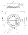
- a radiant heater 1 which consists of a pot 2, in which there is a spirally placed heating coil 3, which is embedded in an investment 4.
- the radiant heater 1 is below the plate 5 made of metal, glass ceramic or the like. arranged, which forms the cooking surface 6. Is between the cooking surface 6 and the heating coil 3 a temperature sensor 7 is arranged which is connected to a switch head 8, wherein the temperature sensor 7 in a simple manner through two holes in the radiant heater 1 is passed.
- the temperature sensor 7 is thus exposed to the temperature below the cooking surface 6 in the radiation space between the cooking surface 6 and the heating coil 3.
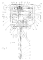
- the unit consisting of temperature sensor 7 and the switching head 8 is separate shown.
- the temperature sensor 7 has a rod 9 made of a high temperature resistant Material with a high coefficient of thermal expansion, for example a nickel-chromium alloy, on in a tube 10 made of a high temperature resistant material with a low coefficient of thermal expansion, for example quartz glass or Ceramic is guided, which forms a shell for the rod 9.
- the switching head 8 is arranged, which with the Temperature sensor 7 is connected as follows.
- the rod 9 projects into the switch head 8 and has at this switch head end a head 52, on which a cylindrical Plate 53 a compression spring 11 is supported. This is also supported on a means of the screws 12, which are provided with threaded holes and held in the switch head 8 Abutment 13 engage, held and a recess 14 of the switch head covering plate 15.
- a sleeve-shaped receptacle 16 is supported, which surrounds the switch end of the tube 10.
- a transmission element 20 is connected to this end of the rod 9 on the switch head side arranged, which is taken along when the rod end 9 is extended. Since no connection is provided between rod 9 and transmission member 20 is to reset the Transmission member 20 when the rod 9 contracts, a spring 21 is provided with its first end on the switching head 8 and with its second end on the transmission element 20 supports and thus biases the transmission member 20 in the direction of the rod 9.
- the primary task of this transmission link 20 is to control the relative movement of the switch end on the rod end towards the contact system connected to the heating circuit transfer. This includes a fixed in the switch head 8 contact 22, which via a Contact carrier 24 is connected to a terminal lug 23.
- This fixed contact 22 acts together with a movable contact 25 which is held on a contact spring 26, which in turn is held on a contact carrier 27 and electrically with another Terminal lug 28 is connected.
- the contact spring 26 has a punched-out tab 29 on, on a support connected to the contact carrier 27 and the contact spring 26 30 is supported.
- the transmission member 20 is located on the contact spring 26, approximately in the central region where it has a transverse rib 31. Temperature-related shifts in the Transmission member 20 thus result in an opening or closing of the contact system. According to the invention, one is already provided in the details described so far known temperature controller to a measuring device arranged in the switch head 8 expand the one relative to the relative movement of the switch head end of the rod 9 the switching head 8 proportional, analog, electrically processable output signal delivers.
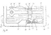
- a particularly preferred embodiment of such a measuring device is a inductive displacement transducer, which in Fig. 3 in the form of a simple plunger anchor transducer is shown.
- This plunger anchor sensor is made of a coil 32 into which a slidable Immersed iron core 33, formed.
- the coil 32 is over its winding body 34 held immovably in the switch head 8, the iron core 33 is slidably mounted and from switch head end of the rod 9 movable.
- the movement caused by the rod 9 Iron core 33 is achieved in that the transmission member 20 over the contact spring 26 extends outward and extends into the area of the coil 32.
- To both the support 30 and the contact spring 26 have openings through which the transmission link 20 is passed through.
- the transmission member 20 In the region of the transverse rib 31 Contact spring 26, the transmission member 20 has a shoulder 54 with which it Contact spring 26 can continue to move.
- the iron core 33 of the Submersible anchor transducer immovably set so that it extends both when extended taken along when pulling the rod 9 and moved relative to the coil 32 becomes.
- This definition is achieved in the embodiment of Figure 3 in that the Iron core 33 is arranged between the transmission member 20 and spring 21.
- the iron core 33 has the shape of a bottom 35 closed on one side, preferably cylindrical tube 36, which with the free surface of its bottom 35th abuts the transmission member 20.
- the spring 21 is formed by a coil spring, which extends into the tube 36 and with its second end on the supports the tube-side surface of the bottom 35.
- the rod 9 is expanded at high temperatures and thus extends far into the switch head 8.
- the iron core 33 is deep in here immersed the coil 32, which state is shown in Figure 3. With dashed lines the position of the iron core 33 at low temperatures is indicated: The rod 9 is contracted, the transmission member 20 is displaced in the direction of the tube 10, whereby the iron core 33 runs only in sections inside the coil.
- Moving the iron core 33 has a change in the properties of the Coil 32 built magnetic circuit result: Is the iron core 33 far into the coil immersed, the magnetic field lines run a further distance inside the coil 32 Iron than in air; If the iron core 33 is pulled out of the coil 32, the run Magnetic field lines a longer distance in air than in iron. Because air and iron are very different Have permeabilities, the iron core shift leads to a change in magnetic resistance and thus to change the inductance of the coil 32. This The change in inductance is (non-linear) proportional to the displacement of the iron core 33, thus proportional to the expansion of the rod 9 and thus ultimately a measure of the Temperature sensor 7 surrounding temperature.
- the two winding ends of the coil 32 are on via electrical lines 55, 56 Connection lugs 37, 38 guided, via which the plunger anchor transducer no longer shown, because circuitry no longer belonging to the actual invention Processing of the measurement signal for a corresponding display is connectable.
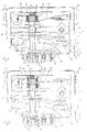
- the embodiment detailed so far is not as the invention thereon to understand restrictively. 4 to 10, to which in the following reference is taken and in which, for the sake of clarity, only the one according to the invention Measuring device-containing section of the switch head 8 is shown, is intended to clarify be that there are a variety of ways of realizing the invention Measuring device there.
- the execution of the iron core 33 as a tube 36 with Floor 35 can be replaced very simply by a cylindrical iron core 33 (cf. Fig. 4).
- the axial guidance of the iron core 33 can, for example, by the Inner circumferential surface of the winding body 34 can be reached.
- here from the Helical form of the spring 21 can be removed and instead e.g. a U-shaped spring, as shown in Fig.10.
- the Measuring device is formed here by a differential plunger sensor, which is analog 3 and 4 again an iron core 33 but has two separate coils 32, 32 '.
- the iron core 33 plunges equally deep into both coils 32, 32 ', it becomes shifted, the inductance of one coil is increased and that of the other is reduced.
- the difference in the inductance changes, which in turn is a measure of the Temperature is to be tapped.
- the inductive transducer of Fig. 6 is a transverse armature transducer.
- the magnetic circuit is a spaced from the core 39 and reconnected to the transmission member 20 Cross anchor 40 closed.
- the movement of the Transverse anchor 40 changes its distance from the core 39, which changes again in the Inductance of the coil 32 expresses.
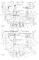
- the measuring device is by a differential transformer educated. It consists of a primary coil 41 and two secondary coils 42, 42 '. Coupled are these coils 42, 42 'over the core 43 which is displaceable in the sleeve 44 and which again has the the transmission link 20 is connected. Those induced in the secondary coils 42,42 ' Voltages are switched against each other.
- the core 43 is in the middle of the two Secondary coils 42, 42 ', the two secondary voltages are the same and the Output voltage of the measuring device is zero. If the core is moved, the output voltage increases one coil, the other one and the difference grows strictly linear with the shift.
- FIG. 8 shows the possibility of using capacitive instead of Inductive displacement transducers shown so far:
- the capacitive transducer comprises a 45 fixed in the switch head 8 and a plate 46 movable by the transmission member 20. By shifting the two plates 45, 46 against each other, the between changes effective area and thus the capacity of the measuring device.
- both capacitor plates 45, 46 are fixed in the switch head 9.
- the Transmission element 20 carries a dielectric lying between the two plates 45, 46 47, which varies in the gap between the plates when the temperature changes is inserted, which also changes the capacity of the measuring arrangement results.
- a temperature controller in which to bias the Transmission member 20 in the direction of the rod 9, a U-shaped spring 48, which is with her first leg 49 on the switching head 8 and with its second leg 50 on the transmission member 20 supports, is provided.
- the measuring device is formed here by at least one strain gauge 51 which is on the U-shaped spring 48 is fixed.
- the U-shaped spring 48 becomes slightly along its outer surface and inversely proportional to Distance between their two legs 49, 50 from each other and thus depending on the temperature of the cooktop.
- This strain is from the strain gauge 51 in a Change in its ohmic resistance implemented on the with the strain gauge 51 connecting lugs connected via the electrical lines 55, 56 37, 38 can be tapped.
- those between the respective Measuring device and the associated terminal lugs 37, 38 extending electrical Lines 55, 56 preferably through conductor tracks applied directly to a thin ceramic plate educated.
- the so-called is used to define these conductor tracks on the ceramic "Direct Copper Bonding" (DCB) process, a particularly good connection from Joining process providing copper and ceramic.
- DCB Direct Copper Bonding
- the measuring device according to the invention can, for example, Wheatstone bridges with which changes in resistance in Changes in their output voltage are implemented.
- those Realizations of the measuring device according to the invention in which an inductor or Capacitance and thus a complex resistance is changed (Fig. 3 to 9), these are To operate Wheatstone measuring bridges with AC voltage.
- the display downstream of the evaluation circuit can e.g. the shape of several in series arranged lamps, the number of illuminated lamps depending is changed by the output signal of the measuring device.
- a Luminous device are used, the color of which is changed by the measurement signal or a pointer instrument connected to the measuring device can be used.
Landscapes
- Physics & Mathematics (AREA)
- General Physics & Mathematics (AREA)
- Chemical & Material Sciences (AREA)
- Engineering & Computer Science (AREA)
- Ceramic Engineering (AREA)
- Thermal Sciences (AREA)
- Thermally Actuated Switches (AREA)
- Measurement Of Length, Angles, Or The Like Using Electric Or Magnetic Means (AREA)
Applications Claiming Priority (3)
| Application Number | Priority Date | Filing Date | Title |
|---|---|---|---|
| AT147597 | 1997-09-03 | ||
| AT147597A AT404776B (de) | 1997-09-03 | 1997-09-03 | Vorrichtung zur heissanzeige |
| AT1475/97 | 1997-09-03 |
Publications (2)
| Publication Number | Publication Date |
|---|---|
| EP0901310A2 true EP0901310A2 (fr) | 1999-03-10 |
| EP0901310A3 EP0901310A3 (fr) | 1999-10-20 |
Family
ID=3514712
Family Applications (1)
| Application Number | Title | Priority Date | Filing Date |
|---|---|---|---|
| EP98890213A Withdrawn EP0901310A3 (fr) | 1997-09-03 | 1998-07-17 | Dispositif pour afficher un état de chauffe |
Country Status (2)
| Country | Link |
|---|---|
| EP (1) | EP0901310A3 (fr) |
| AT (1) | AT404776B (fr) |
Cited By (4)
| Publication number | Priority date | Publication date | Assignee | Title |
|---|---|---|---|---|
| EP1223597A1 (fr) * | 2001-01-10 | 2002-07-17 | Electrovac, Fabrikation Elektrotechnischer Spezialartikel Gesellschaft M.B.H. | Limiteur de température |
| US6646538B2 (en) * | 2001-04-17 | 2003-11-11 | Electrovac, Fabrikation Elektrotechnischer Spezialartikel Gesellschft M.B.H. | Temperature limiter, and calibration method for operating a switching contact of a temperature limiter |
| EP1569257A1 (fr) * | 2004-02-24 | 2005-08-31 | Electrovac Fabrikation Elektrotechnischer Spezialartikel Gesellschaft M.B.H. | Capteur de température |
| WO2010006590A1 (fr) * | 2008-07-18 | 2010-01-21 | Micro-Epsilon Messtechnik Gmbh & Co. Kg | Dispositif de mesure de température et procédé de mesure de la température |
Family Cites Families (2)
| Publication number | Priority date | Publication date | Assignee | Title |
|---|---|---|---|---|
| DD101012A1 (fr) * | 1972-12-01 | 1973-10-12 | ||
| DE4325515A1 (de) * | 1993-07-29 | 1995-02-02 | Bosch Siemens Hausgeraete | Kochfeldtemperaturanzeige |
-
1997
- 1997-09-03 AT AT147597A patent/AT404776B/de not_active IP Right Cessation
-
1998
- 1998-07-17 EP EP98890213A patent/EP0901310A3/fr not_active Withdrawn
Cited By (6)
| Publication number | Priority date | Publication date | Assignee | Title |
|---|---|---|---|---|
| EP1223597A1 (fr) * | 2001-01-10 | 2002-07-17 | Electrovac, Fabrikation Elektrotechnischer Spezialartikel Gesellschaft M.B.H. | Limiteur de température |
| US6724294B2 (en) | 2001-01-10 | 2004-04-20 | Electrovac, Fabrikation Elektrotechnischer Spezialartikel Gesellschaft M.B.H. | Temperature limiter |
| US6646538B2 (en) * | 2001-04-17 | 2003-11-11 | Electrovac, Fabrikation Elektrotechnischer Spezialartikel Gesellschft M.B.H. | Temperature limiter, and calibration method for operating a switching contact of a temperature limiter |
| EP1569257A1 (fr) * | 2004-02-24 | 2005-08-31 | Electrovac Fabrikation Elektrotechnischer Spezialartikel Gesellschaft M.B.H. | Capteur de température |
| US7345572B2 (en) | 2004-02-24 | 2008-03-18 | Electrovac, Fabrikation Elektrotechnischer Spezialartikel Ges.M.B.H. | Temperature sensor |
| WO2010006590A1 (fr) * | 2008-07-18 | 2010-01-21 | Micro-Epsilon Messtechnik Gmbh & Co. Kg | Dispositif de mesure de température et procédé de mesure de la température |
Also Published As
| Publication number | Publication date |
|---|---|
| AT404776B (de) | 1999-02-25 |
| ATA147597A (de) | 1998-06-15 |
| EP0901310A3 (fr) | 1999-10-20 |
Similar Documents
| Publication | Publication Date | Title |
|---|---|---|
| DE3229380C2 (fr) | ||
| DE4022845C2 (fr) | ||
| DE69317453T2 (de) | Vorrichtung zur Steuerung oder Begrenzung der Temperatur in einem elektrischen Kochgerät | |
| DE3346582C2 (de) | Vorrichtung zur Steuerung von wenigstens zwei Heizzonen aufweisenden Heizkörpern für Kochgeräte | |
| DE10035745B4 (de) | Temperaturerfassungseinrichtung für einen elektrischen Strahlungsheizkörper | |
| EP1154675B1 (fr) | Dispositif et méthode de régulation de chauffage d'une plaque céramique | |
| EP1223597B1 (fr) | Limiteur de température | |
| DE2839161A1 (de) | Temperaturbegrenzer fuer eine glaskeramik-kocheinheit | |
| WO1997016943A2 (fr) | Dispositif de cuisson | |
| DE3623473A1 (de) | Anordnung und verfahren zum eichen einer temperaturmessvorrichtung | |
| AT404776B (de) | Vorrichtung zur heissanzeige | |
| EP1709837B1 (fr) | Dispositif pour rechauffer des plats par couplage inductif et dispositif de transfert d'energie | |
| EP0498386A1 (fr) | Capteur de température et procédé pour sa fabrication | |
| EP0416335A1 (fr) | Interrupteur thermique | |
| DE3423085A1 (de) | Vorrichtung zur regelung bzw. begrenzung wenigstens eines temperaturwertes bzw. eines temperaturbereiches von strahlungs- bzw. kontaktheizkoerpern | |
| DE19925367A1 (de) | Temperatursensor | |
| EP1458003B1 (fr) | Capteur de température | |
| DE3623130A1 (de) | Strahlungsbeheizung | |
| AT409680B (de) | Temperaturbegrenzer | |
| EP0114307B1 (fr) | Dispositif de régulation de la température d'un appareil de chauffage | |
| DE4313273A1 (de) | Auswerteverfahren und -schaltung für einen induktiven Sensor | |
| EP1339260B1 (fr) | Capteur de température | |
| DE102004058473B4 (de) | Heizeinrichtung, insbesondere Strahlungsheizkörper | |
| DE9201797U1 (de) | Kunststoff-Spritzdüse mit Rohrheizkörper und integriertem Thermoelement | |
| AT406911B (de) | Temperatursensor |
Legal Events
| Date | Code | Title | Description |
|---|---|---|---|
| PUAI | Public reference made under article 153(3) epc to a published international application that has entered the european phase |
Free format text: ORIGINAL CODE: 0009012 |
|
| AK | Designated contracting states |
Kind code of ref document: A2 Designated state(s): AT BE CH CY DE DK ES FI FR GB GR IE IT LI LU MC NL PT SE |
|
| AX | Request for extension of the european patent |
Free format text: AL;LT;LV;MK;RO;SI |
|
| PUAL | Search report despatched |
Free format text: ORIGINAL CODE: 0009013 |
|
| AK | Designated contracting states |
Kind code of ref document: A3 Designated state(s): AT BE CH CY DE DK ES FI FR GB GR IE IT LI LU MC NL PT SE |
|
| AX | Request for extension of the european patent |
Free format text: AL;LT;LV;MK;RO;SI |
|
| AKX | Designation fees paid | ||
| REG | Reference to a national code |
Ref country code: DE Ref legal event code: 8566 |
|
| STAA | Information on the status of an ep patent application or granted ep patent |
Free format text: STATUS: THE APPLICATION IS DEEMED TO BE WITHDRAWN |
|
| 18D | Application deemed to be withdrawn |
Effective date: 20000421 |