EP0901335B1 - Badvorrichtung, wannenträger und montierverfahren - Google Patents
Badvorrichtung, wannenträger und montierverfahren Download PDFInfo
- Publication number
- EP0901335B1 EP0901335B1 EP97919861A EP97919861A EP0901335B1 EP 0901335 B1 EP0901335 B1 EP 0901335B1 EP 97919861 A EP97919861 A EP 97919861A EP 97919861 A EP97919861 A EP 97919861A EP 0901335 B1 EP0901335 B1 EP 0901335B1
- Authority
- EP
- European Patent Office
- Prior art keywords
- front panel
- stand
- mounting
- legs
- bath
- Prior art date
- Legal status (The legal status is an assumption and is not a legal conclusion. Google has not performed a legal analysis and makes no representation as to the accuracy of the status listed.)
- Expired - Lifetime
Links
Images


Classifications
-
- A—HUMAN NECESSITIES
- A47—FURNITURE; DOMESTIC ARTICLES OR APPLIANCES; COFFEE MILLS; SPICE MILLS; SUCTION CLEANERS IN GENERAL
- A47K—SANITARY EQUIPMENT; ACCESSORIES THEREFOR, e.g. TOILET ACCESSORIES
- A47K3/00—Baths; Showers; Appurtenances therefor
- A47K3/16—Devices for fastening baths to floors or walls; Adjustable bath feet ; Lining panels or attachments therefor
Definitions
- the present invention relates to a bath arrangement comprising a bath, a stand and at least one detachable front panel as well as a method of mounting such a bath arrangement.
- the invention also concerns a stand for a bath and a method of mounting such a stand.
- front panel for such sides of a bath.
- shower tubs the sides of which may be coated with fronts correspondingly.
- fronts are also called front panels, and by the term bath is also meant such a shower tub.
- the bath is standing on legs which are mounted at the bottom of the bath and the front panels are detachably fixed to the edge of the bath by means of clamps or hooks.
- the front panels on the side wall and the end wall of the bath are then fixed to each other or to the corner legs by means of some sort of hook or clip.
- the drawback of such an arrangement is that the front panel is often unwieldy and heavy to handle, and in such an arrangement, the front panel must be raised and its upper edge must be aligned with the bath during a relatively long period of time so as to fit the front panel into receiving means at the edge of the bath. This movement requires accuracy and is often carried out in an inconvenient working position.
- a further drawback of such a construction is that mounting and dismounting of the bath arrangement are time-consuming and require tools. It is also disadvantageous that the vertical position of the front panels is not quite stable which may give an unsatisfactory aesthetic impression.
- SE-364,864 discloses an arrangement in baths for suspension of an end plate and/or a front plate.
- the plates are suspended by means of special corner mountings which are arranged at the edge bead located at the top of the bath.
- the corner mountings are made of plastic, for instance propylene, and both right-hand and left-hand corner mountings are necessary.
- the plates are detachable, and a special tool for this purpose is also described.
- SE-B-446,369 discloses a bath front panel which is divided into a number of front panel parts. These front panel parts are attached in recesses in fixing irons, which are suspended vertically from the edge bead of the bath and the lower portions of which are fixed in a supporting bracket. In fact, this construction makes it possible to remove the front panel without any great effort, but the removal of the entire front panel is a complicated operation. The installation and mounting of new bath arrangements of this kind are very time-consuming and require equipment and experience.
- a further known bath arrangement is disclosed in FR-B-1,357,499, in which a bath having a pivotable front panel is described.
- This construction implies that corner parts are screwed onto the edge of the bath.
- Each corner part is in its upper portion provided with pins which are adapted to form, in coaction with holes in the upper portion of the front panel, a pivot, which permits pivoting of the front panel so as to facilitate cleaning.
- the front panels and the corner parts are attached to each other by means of screws.
- the construction is difficult and time-consuming to assemble and is impractical in cleaning since the front panel must be held with one hand and cleaned with the other.
- a further variant of a bath arrangement is disclosed in SE-B-470,004.
- two fixed front panels are attached to the stand of the arrangement or to the frame of the bath.
- the front panels are provided with bushes for the supporting of pins on an intermediate front panel, which are adapted to form a pivot.
- the intermediate front panel is secured in its inwardly pivoted position by means of e.g. Velcro fasteners and in its vertical position by means of catches or Velcro fasteners.
- This variant allows cleaning under the bath, but the front panel is difficult to remove completely for e.g. repairs or inspection. Besides, the time it takes to mount and install new baths is found to be unnecessarily long.
- GB-659,239 discloses a bath with front panels that are attached by means of male and female members. However, the front panels are not detachable after mounting.
- a bath arrangement according to the preamble of claim 1 and a stand for baths according to the preamble of claim 11 are known from the document EP 0 197 183 A.
- One object of the present invention thus is to provide a bath arrangement which allows mounting without loose mounting components, the front panel still being detachable.
- a further object of the invention is to provide a bath arrangement which is quick and easy to install.
- a further object is to provide a stand for a bath and a quick and easy method of mounting a stand.
- One more object of the invention is to provide a rational method of mounting bath arrangements.
- the invention bath arrangement has the characteristic features as stated in the characterising clause of claim 1.
- the stand according to the invention has the characteristic features stated in the characterising clause of claim 11.
- An advantage of the invention is that difficult lifting operations are avoided when removing the front panels and that such removal can be carried out without tools and special previous training.
- a further advantage of the invention is that the front panels are stable in their vertical position.
- One more advantage of the invention is that packing, storing and transporting will be both less expensive and easier since the stand needs less space and can be mounted where the bath is to be located.
- the stand requires no loose mounting components.
- the legs of the bath arrangement are provided at their one end with suspension means intended for the front panel and at their other end with clamping means.
- the suspension means allow pivoting of the front panel in relation to the stand and the suspension means.
- the front panel is formed with holes corresponding to the suspension means and pins corresponding to the clamping means.
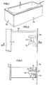
- Fig. 1 shows a mounted and installed bath arrangement 1 which comprises a bath 2 and two so-called front panels 3a and 3b.
- Fig. 2 shows the bath arrangement 1 in Fig. 1 in its unmounted state without the actual bath 2 and illustrates a stand 4 which in this embodiment consists of four legs 5, two elongate parts 6, two transverse parts 7 and four essentially triangular corner parts 8 for supporting the bath 2.
- the stand may also be of another design, for instance the number of legs may vary.
- the legs also need not be interconnected but can be fixed to, for instance, the floor or the bath.
- the corner parts may have any form that fits the bath involved.
- the elongate parts 6 and the transverse parts 7 consist of essentially C-shaped sectional elements, the end portions of which are flat, as shown in Fig. 2.
- the elongate parts 6 and the transverse parts 6 have mounting means coacting with corresponding mounting means of the legs 5.
- the mounting means of the parts consist of at least one hook 24 at each end of the parts, said hooks being integrally formed with the respective parts 6, 7.
- the mounting means of the legs 5 consist of corresponding slots 25 having a pressed-in portion 26 in the legs.
- the mounting means consist of two hooks 24 at each end portion and two corresponding slots 25.
- the stability increases when using two mounting means instead of one at each end portion.
- the hooks 24 of the elongate parts and the transverse parts are inserted into corresponding pressed-in portions 26 in the legs 5 and are hooked into corresponding slots 25.
- the hooks have at their upper end a projection 27, as shown in Fig. 7.
- the C-type sectional elements are. locked to the legs when this projection 27 has passed the lower edge of the pressed-in portion 26.
- the parts 6, 7 are preferably made of metal.
- the sectional element is bent to a suitable shape, and the hooks 24 are bent out of the material of the sectional element.
- the leg 5 will be produced as described below.
- each leg At the bottom of each leg there is an adjusting means which allows adjustment of the stand to make it balanced. The stand is now ready for insertion of the bath.
- the stand may also be used for other types of suspension means and coupling means for the front panel than those appearing from the application.
- Each of the legs 5 is at its lower part provided with suspension means 9 which comprise a portion 10 extending transversely of the leg 5 and an upwardly directed flap 11 which extends essentially in parallel with the leg 5.
- the suspension means 9 can be attached to the leg 5 in various ways, for instance by welding, gluing or with the aid of a screw (not shown).
- the suspension means 9 is made of the material of the leg 5, see Figs 2, 5 and 6, which simplifies the manufacture to a considerable extent. Welding requiring semiskilled workers and being expensive and dangerous in connection with sparking will not be necessary either.
- the suspension means can also be designed and located in other positions, for instance in the form of a ball in the centre of the leg for supporting a front panel that just extends over part of the length of the leg.
- the front panels 3a and 3b are formed with holes 12, for instance in the form of rectangular punchings.
- the holes 12 may have any contour that fits the corresponding suspension means 9, and alternatively, the holes 12 are formed in the respective legs 5 and the suspension means 9 are arranged on the respective front panels 3a, 3b.
- Each of the legs 5 is also provided with a clamping means 13, which constitutes the female member of a coupling means adapted to fix the front panels 3a, 3b to the stand 4.
- the clamping means 13 comprises a mounting 14 arranged on the leg 5 and being in the form of an angular mounting with a hole 15 (see Fig. 2), into which a clamp 16 is inserted (see Figs 3 and 4). The fits are preferably such as to let the clamp 16 remain in the hole 15 once it is inserted.
- the clamp 16 comprises a bent body 17 with fixing flaps 18 grasping the edge of the hole 15.
- the body 17 has two opposing, spaced-apart clamping flaps 19, each having a bent edge portion 20.
- the front panels 3a and 3b are provided with a corresponding male member in the form of a pin 21 with a thickened pointed portion 22 and a waist portion 23.
- the pin 21 is adapted to be pressed against the clamping flaps 19, thereby moving them apart and making them spring back so as to clamp the waist portion 23 of the pin 21.
- the bent edge portions 20 of the clamping flaps 19 prevent the pointed portion 22 of the pin 21 from sliding back.
- the mounting 14 can be arranged on the leg 5 in various ways, for instance by welding, gluing or with the aid of a screw (not shown).
- the mounting 14 is made of the material of the leg 5, see Figs 2, 5 and 6, which simplifies the manufacture to a considerable extent. Welding, which requires semiskilled workers and is expensive and dangerous in connection with sparking, will not be necessary either.
- the mounting may also have a form other than an angular mounting, for instance it may be formed as a hollow semi-sphere of a rectangular mounting (not shown).
- the clamp 16 is so designed as to have two horizontally arranged clamping flaps, and according to another embodiment, it has a number of clamping flaps (not shown) arranged radially from the space.
- the space may also be rectangular, circular or of any other shape, and consequently the pin may be of any shape whatever that corresponds to the shape of the space, thereby forming an efficient clamping device.
- the clamp 16 may also be arranged on the front panel 3 and the pin 21 on the leg 5.
- mounting means 25, 26, coupling means 13 and suspension means 9 are formed integrally with the leg 5.
- the appearance of the leg is shown in Fig. 6.
- the entire leg 5 and all these means can thus be made in one piece.
- a blank for such a leg is illustrated in Fig. 5.
- all three types of means are formed integrally with the leg.
- the leg 5 is preferably made of metal and is produced from the blank shown in Fig. 5.
- the slots 25 and the holes 15 are punched, the mountings 14 and the portions 10 and the flaps 11 are bent outwards, the portions 26 are pressed inwards, and the blank is bent along the dash-dot line in Fig. 5. After such machining, the leg has the appearance as shown in Fig. 6.
- Either the mountings 14 or the portions 10 or both may have reinforcements in the form of semicircular pressed-in portions extending along the mountings 14 and/or the portions 10 and a distance onto the material of the leg 5.
- the front panel 3a When dismounting, one grasps the edge of the front panel 3a, preferably in the vicinity of the snap-acting coupling means 13, 21 and pulls the front panel 3a towards oneself.
- the pin 21 releases the clamp 16 and the front panel 3a can either be pivoted outwards or easily be lifted off from the suspension means 9.
- the front panel 3b is mounted and dismounted correspondingly.
- the bath arrangement according to the invention thus has a detachable front panel and is mountable without any loose mounting components.
Landscapes
- Health & Medical Sciences (AREA)
- Public Health (AREA)
- Epidemiology (AREA)
- General Health & Medical Sciences (AREA)
- Residential Or Office Buildings (AREA)
- Devices For Medical Bathing And Washing (AREA)
- Percussion Or Vibration Massage (AREA)
- Polarising Elements (AREA)
Claims (13)
- Wannenvorrichtung, die eine Wanne (2), ein Gestell (4) mit Füßen (5) und wenigstens eine abnehmbare Außenverkleidung (3a, 3b) umfasst, wobei die Außenverkleidung (3a, 3b) mit Hilfe wenigstens einer Einschnappverbindungseinrichtung, die ein Einführelement (21), das an der Außenverkleidung (3a, 3b) angeordnet ist, und ein Aufnahmeelement (13), das an dem Gestell (4) angeordnet ist, umfasst, abnehmbar an dem Gestell (4) befestigt ist, dadurch gekennzeichnet, dass das Aufnahmeelement (13) eine Anbringung (14), die aus dem Material des Fußes (5) besteht, integral mit dem Fuß umfasst, wobei die Außenverkleidung (3a, 3b) ohne jegliche lose Anbringungsbauteile lösbar befestigt.
- Wannenvorrichtung nach Anspruch 1, wobei die Außenverkleidung (3a, 3b) oder das Gestell (4) mit Aufhängungseinrichtungen (9) versehen ist, die mit Löchern (12) in dem Gestell (4) bzw. der Außenverkleidung (3a, 3b) zusammenwirken, um eine Schwenkverbindung zwischen der Außenverkleidung (3a, 3b) und dem Gestell (4) zu bilden.
- Wannenvorrichtung nach Anspruch 2, wobei die Aufhängungseinrichtungen (3) aus dem Material der Füße (5) bestehen.
- Wannenvorrichtung nach einem der vorangehenden Ansprüche, wobei es sich bei dem Einführelement um einen Zapfen (21) handelt, der einen Spitzenabschnitt (22) und einen Einschnürungsabschnitt (23) aufweist und der in das Aufnahmeelement (13) eingeführt wird, das einander gegenüberliegende Zungen (19) mit einem minimalen Abstand zueinander umfasst, der kleiner ist als die Dicke des Spitzenabschnitts (22) des Zapfens (21).
- Wannenvorrichtung nach einem der Ansprüche 2-4, wobei die Aufhängungseinrichtung (9) einen Abschnitt (10), der sich quer zu dem Fuß (5) erstreckt, und eine Zunge, die sich im Wesentlichen parallel zu dem Fuß (5) erstreckt, umfasst.
- Wannenvorrichtung nach einem der vorangehenden Ansprüche, wobei die Anbringung (14) des Aufnahmeelementes ein Loch (15) aufweist, in das eine Klemme (16) eingeführt ist, die wenigstens eine Klemmzunge (19) aufweist, die mit dem Einführelement (21) in Eingriff kommt.
- Wannenvorrichtung nach Anspruch 6, wobei die Klemme (16) einen gebogenen Körper (17) mit Befestigungszungen (18), die um den Rand des Lochs (15) herumgreifen, und zwei einander gegenüberliegende Klemmzungen (19) umfasst.
- Wannenvorrichtung nach Anspruch 7, wobei die Klemmzungen (9) gebogene Kanten (20) zum Halten des Einführelementes (21) aufweisen.
- Wannenvorrichtung nach einem der vorangehenden Ansprüche, wobei die Füße (5) des Gestells (4) durch Längsteile (6) und Querteile (7) miteinander verbunden sind und die Teile (6, 7) Anbringungseinrichtungen aufweisen, die mit entsprechenden Anbringungseinrichtungen der Füße (5) zusammenwirken.
- Wannenvorrichtung nach Anspruch 9, wobei die Anbringungseinrichtungen der Teile (6, 7) aus wenigstens einem Haken (24) an jedem Ende der Teile bestehen, wobei die Haken (24) integral mit den entsprechenden Teilen (6, 7) ausgebildet sind, und die Anbringungseinrichtungen der Füße (5) aus entsprechenden Schlitzen (25) mit einem eingedrückten Abschnitt (26) in den Füßen (5) bestehen.
- Gestell für Wannen mit einer Einrichtung zum Anbringen einer Außenverkleidung (3a, 3b), wobei das Gestell Füße (5) umfasst und die Außenverkleidung (3a, 3b) mit Hilfe wenigstens einer Einschnapp-Verbindungseinrichtung, die ein Einführelement (21), das an der Außenverkleidung (3a, 3b) angeordnet ist, und ein Aufnahmeelement (13), das an dem Gestell (4) angeordnet ist, umfasst, lösbar an dem Gestell (4) befestigt werden kann, dadurch gekennzeichnet, dass die Außenverkleidung (3a, 3b) ohne jegliche lose Anbringungsbauteile lösbar befestigt werden kann, dass das Aufnahmeelement (13) eine Anbringung (14) umfasst, die aus dem Material eines der Füße (5) besteht und eine Einheit damit bildet, wobei die Füße (5) durch Längsteile (6) und Querteile (7) miteinander verbunden sind und die Teile (6, 7) Anbringungseinrichtungen aufweisen, die mit entsprechenden Anbringungseinrichtungen der Füße (5) zusammenwirken, dass die Anbringungseinrichtungen der Teile (6, 7) aus wenigstens einem Haken an jedem Ende der Teile bestehen, wobei die Haken (24) integral mit den entsprechenden Teilen (6, 7) ausgebildet sind, und dass die Anbringungseinrichtungen der Füße (5) aus entsprechenden Schlitzen (25) mit einem eingedrückten Abschnitt (26) in den Füßen (5) bestehen.
- Verfahren zum Montieren eines Gestells (4) nach Anspruch 11, dadurch gekennzeichnet, dass die Haken (24) der Längsteile (6) und die Haken (24) der Querteile (7) in die eingedrückten Abschnitte (26) in den Füßen (5) eingeführt werden und in entsprechenden Schlitzen (25) eingehängt werden, wobei das Gestell ohne jegliche lose Anbringungsbauteile montiert werden kann.
- Verfahren zum Montieren einer Wannenvorrichtung nach Anspruch 1, gekennzeichnet durch die folgenden Schritte:a) schwenkbares Verbinden der Außenverkleidung (3a, 3b) an ihrer oberen oder unteren Längskante mit dem Gestell (4) an zwei beabstandeten Verbindungspunkten (9), undb) Schwenken der Außenverkleidung (3a, 3b) in eine im Wesentlichen vertikale Position, in der Eingriffseinrichtungen (21), die sich an der gegenüberliegenden Längskante der Außenverkleidung (3a, 3b) befinden, mit entsprechenden Eingriffseinrichtungen (13) an dem Gestell (4) in Eingriff gebracht werden, um die Außenverkleidung (3a, 3b) zu halten, wobei die Wannenvorrichtung ohne jegliche lose Anbringungsbauteile montiert werden kann.
Applications Claiming Priority (3)
| Application Number | Priority Date | Filing Date | Title |
|---|---|---|---|
| SE9602097A SE9602097D0 (sv) | 1996-05-29 | 1996-05-29 | Badkarsanordning |
| SE9602097 | 1996-05-29 | ||
| PCT/SE1997/000617 WO1997045047A1 (en) | 1996-05-29 | 1997-04-11 | Bath arrangement, stand and method of mounting |
Publications (2)
| Publication Number | Publication Date |
|---|---|
| EP0901335A1 EP0901335A1 (de) | 1999-03-17 |
| EP0901335B1 true EP0901335B1 (de) | 2002-07-24 |
Family
ID=20402777
Family Applications (1)
| Application Number | Title | Priority Date | Filing Date |
|---|---|---|---|
| EP97919861A Expired - Lifetime EP0901335B1 (de) | 1996-05-29 | 1997-04-11 | Badvorrichtung, wannenträger und montierverfahren |
Country Status (6)
| Country | Link |
|---|---|
| EP (1) | EP0901335B1 (de) |
| AT (1) | ATE220874T1 (de) |
| AU (1) | AU2419597A (de) |
| DE (1) | DE69714250T2 (de) |
| SE (1) | SE9602097D0 (de) |
| WO (1) | WO1997045047A1 (de) |
Families Citing this family (3)
| Publication number | Priority date | Publication date | Assignee | Title |
|---|---|---|---|---|
| GB2348600A (en) * | 1999-02-16 | 2000-10-11 | Bendz Limited | A height adjustable bath support |
| CH713682A1 (de) * | 2017-04-10 | 2018-10-15 | Sanipat Gmbh | Bausatz für einen Wannenträger. |
| EP3387971B1 (de) * | 2017-04-10 | 2021-03-17 | Sanipat GmbH | Bausatz für einen wannenträger |
Family Cites Families (7)
| Publication number | Priority date | Publication date | Assignee | Title |
|---|---|---|---|---|
| GB659239A (en) * | 1949-06-16 | 1951-10-17 | Allied Ironfounders Ltd | Improvements in or relating to baths |
| US3028603A (en) * | 1960-07-14 | 1962-04-10 | Clarence J Rodman | Detachable bathtub apron |
| SE364864B (de) * | 1972-11-03 | 1974-03-11 | Ifoe Ab | |
| SE455366B (sv) * | 1983-11-04 | 1988-07-11 | Ifoe Sanitaer Ab | Gavelplatsupphengning for badkar |
| DE3509703A1 (de) * | 1985-03-18 | 1986-09-18 | Gebr. Bamberger GmbH & Co KG, 3563 Dautphetal | Segmentfoermige wanne |
| IT212010Z2 (it) * | 1987-10-19 | 1989-05-25 | Jacuzzi Europ | Base attrezzata per vasche dabagno, specialmente vasche munite di impianto di idromassaggio. |
| DE9404956U1 (de) * | 1994-03-23 | 1994-05-26 | Altura Leiden Holding B.V., Maastricht | Montagerahmen |
-
1996
- 1996-05-29 SE SE9602097A patent/SE9602097D0/xx unknown
-
1997
- 1997-04-11 WO PCT/SE1997/000617 patent/WO1997045047A1/en not_active Ceased
- 1997-04-11 AU AU24195/97A patent/AU2419597A/en not_active Abandoned
- 1997-04-11 EP EP97919861A patent/EP0901335B1/de not_active Expired - Lifetime
- 1997-04-11 AT AT97919861T patent/ATE220874T1/de not_active IP Right Cessation
- 1997-04-11 DE DE69714250T patent/DE69714250T2/de not_active Expired - Fee Related
Also Published As
| Publication number | Publication date |
|---|---|
| WO1997045047A1 (en) | 1997-12-04 |
| EP0901335A1 (de) | 1999-03-17 |
| SE9602097D0 (sv) | 1996-05-29 |
| DE69714250T2 (de) | 2003-02-27 |
| ATE220874T1 (de) | 2002-08-15 |
| AU2419597A (en) | 1998-01-05 |
| DE69714250D1 (de) | 2002-08-29 |
Similar Documents
| Publication | Publication Date | Title |
|---|---|---|
| US5624168A (en) | Cabinet mounting apparatus | |
| US6449917B1 (en) | Suspended acoustical ceiling system | |
| US4696113A (en) | Apparatus for locating the outline of an accessory in dry wall or a decorative panel | |
| EP0901335B1 (de) | Badvorrichtung, wannenträger und montierverfahren | |
| JPH04258433A (ja) | 壁付属品係止用固定具 | |
| JP2961502B2 (ja) | 点検口の蓋の取付方法とその方法に使用される取付具 | |
| FI89668C (fi) | Arrangemang foer att faesta en bordsskiva vid bordets fotdel | |
| KR100419526B1 (ko) | 간이착탈형 2축경첩구조 | |
| JP2975236B2 (ja) | 浴室のカウンター取付構造 | |
| JP4090360B2 (ja) | 天井板取付具 | |
| CN101668471B (zh) | 抽屉式洗碗机成套装配组件 | |
| JP2639210B2 (ja) | 天板付家具 | |
| JPS6217613Y2 (de) | ||
| JPH0819486A (ja) | 棚及び棚取付け具 | |
| CN219535410U (zh) | 一种电控箱接线安装用支架 | |
| JPH10295573A (ja) | エプロン付き浴槽 | |
| JPH09228543A (ja) | 吹抜部の天井構造 | |
| KR0132395Y1 (ko) | 주방용 선반 | |
| JPH047788Y2 (de) | ||
| JPH0312313Y2 (de) | ||
| JP6797474B2 (ja) | 浴室用カウンター | |
| JPS5914548Y2 (ja) | 設備ユニツト | |
| JPH08135135A (ja) | 配管ユニットの前板取付構造および取付け方法 | |
| KR920004008Y1 (ko) | 선반 고정구 | |
| JPH02256729A (ja) | はめ込形洗面器の取付方法 |
Legal Events
| Date | Code | Title | Description |
|---|---|---|---|
| PUAI | Public reference made under article 153(3) epc to a published international application that has entered the european phase |
Free format text: ORIGINAL CODE: 0009012 |
|
| 17P | Request for examination filed |
Effective date: 19981201 |
|
| AK | Designated contracting states |
Kind code of ref document: A1 Designated state(s): AT BE CH DE DK ES FI FR GB GR IE IT LI LU MC NL PT SE |
|
| 17Q | First examination report despatched |
Effective date: 20010417 |
|
| GRAG | Despatch of communication of intention to grant |
Free format text: ORIGINAL CODE: EPIDOS AGRA |
|
| GRAG | Despatch of communication of intention to grant |
Free format text: ORIGINAL CODE: EPIDOS AGRA |
|
| GRAH | Despatch of communication of intention to grant a patent |
Free format text: ORIGINAL CODE: EPIDOS IGRA |
|
| GRAH | Despatch of communication of intention to grant a patent |
Free format text: ORIGINAL CODE: EPIDOS IGRA |
|
| GRAA | (expected) grant |
Free format text: ORIGINAL CODE: 0009210 |
|
| AK | Designated contracting states |
Kind code of ref document: B1 Designated state(s): AT BE CH DE DK ES FI FR GB GR IE IT LI LU MC NL PT SE |
|
| PG25 | Lapsed in a contracting state [announced via postgrant information from national office to epo] |
Ref country code: NL Free format text: LAPSE BECAUSE OF FAILURE TO SUBMIT A TRANSLATION OF THE DESCRIPTION OR TO PAY THE FEE WITHIN THE PRESCRIBED TIME-LIMIT Effective date: 20020724 Ref country code: IT Free format text: LAPSE BECAUSE OF FAILURE TO SUBMIT A TRANSLATION OF THE DESCRIPTION OR TO PAY THE FEE WITHIN THE PRESCRIBED TIME-LIMIT;WARNING: LAPSES OF ITALIAN PATENTS WITH EFFECTIVE DATE BEFORE 2007 MAY HAVE OCCURRED AT ANY TIME BEFORE 2007. THE CORRECT EFFECTIVE DATE MAY BE DIFFERENT FROM THE ONE RECORDED. Effective date: 20020724 Ref country code: GR Free format text: LAPSE BECAUSE OF FAILURE TO SUBMIT A TRANSLATION OF THE DESCRIPTION OR TO PAY THE FEE WITHIN THE PRESCRIBED TIME-LIMIT Effective date: 20020724 Ref country code: FR Free format text: LAPSE BECAUSE OF NON-PAYMENT OF DUE FEES Effective date: 20020724 Ref country code: BE Free format text: LAPSE BECAUSE OF FAILURE TO SUBMIT A TRANSLATION OF THE DESCRIPTION OR TO PAY THE FEE WITHIN THE PRESCRIBED TIME-LIMIT Effective date: 20020724 |
|
| REF | Corresponds to: |
Ref document number: 220874 Country of ref document: AT Date of ref document: 20020815 Kind code of ref document: T |
|
| REG | Reference to a national code |
Ref country code: GB Ref legal event code: FG4D |
|
| REG | Reference to a national code |
Ref country code: CH Ref legal event code: EP |
|
| REG | Reference to a national code |
Ref country code: IE Ref legal event code: FG4D |
|
| REF | Corresponds to: |
Ref document number: 69714250 Country of ref document: DE Date of ref document: 20020829 |
|
| PG25 | Lapsed in a contracting state [announced via postgrant information from national office to epo] |
Ref country code: PT Free format text: LAPSE BECAUSE OF FAILURE TO SUBMIT A TRANSLATION OF THE DESCRIPTION OR TO PAY THE FEE WITHIN THE PRESCRIBED TIME-LIMIT Effective date: 20021024 Ref country code: DK Free format text: LAPSE BECAUSE OF FAILURE TO SUBMIT A TRANSLATION OF THE DESCRIPTION OR TO PAY THE FEE WITHIN THE PRESCRIBED TIME-LIMIT Effective date: 20021024 |
|
| REG | Reference to a national code |
Ref country code: CH Ref legal event code: NV Representative=s name: PATENTANWAELTE FELDMANN & PARTNER AG |
|
| NLV1 | Nl: lapsed or annulled due to failure to fulfill the requirements of art. 29p and 29m of the patents act | ||
| PG25 | Lapsed in a contracting state [announced via postgrant information from national office to epo] |
Ref country code: ES Free format text: LAPSE BECAUSE OF FAILURE TO SUBMIT A TRANSLATION OF THE DESCRIPTION OR TO PAY THE FEE WITHIN THE PRESCRIBED TIME-LIMIT Effective date: 20030130 |
|
| EN | Fr: translation not filed | ||
| PGFP | Annual fee paid to national office [announced via postgrant information from national office to epo] |
Ref country code: GB Payment date: 20030404 Year of fee payment: 7 |
|
| PG25 | Lapsed in a contracting state [announced via postgrant information from national office to epo] |
Ref country code: LU Free format text: LAPSE BECAUSE OF NON-PAYMENT OF DUE FEES Effective date: 20030411 Ref country code: IE Free format text: LAPSE BECAUSE OF NON-PAYMENT OF DUE FEES Effective date: 20030411 |
|
| PGFP | Annual fee paid to national office [announced via postgrant information from national office to epo] |
Ref country code: SE Payment date: 20030416 Year of fee payment: 7 |
|
| PGFP | Annual fee paid to national office [announced via postgrant information from national office to epo] |
Ref country code: FI Payment date: 20030417 Year of fee payment: 7 Ref country code: DE Payment date: 20030417 Year of fee payment: 7 |
|
| PGFP | Annual fee paid to national office [announced via postgrant information from national office to epo] |
Ref country code: AT Payment date: 20030418 Year of fee payment: 7 |
|
| PGFP | Annual fee paid to national office [announced via postgrant information from national office to epo] |
Ref country code: CH Payment date: 20030424 Year of fee payment: 7 |
|
| PG25 | Lapsed in a contracting state [announced via postgrant information from national office to epo] |
Ref country code: MC Free format text: LAPSE BECAUSE OF NON-PAYMENT OF DUE FEES Effective date: 20030430 |
|
| PLBE | No opposition filed within time limit |
Free format text: ORIGINAL CODE: 0009261 |
|
| STAA | Information on the status of an ep patent application or granted ep patent |
Free format text: STATUS: NO OPPOSITION FILED WITHIN TIME LIMIT |
|
| 26N | No opposition filed |
Effective date: 20030425 |
|
| REG | Reference to a national code |
Ref country code: IE Ref legal event code: MM4A |
|
| PG25 | Lapsed in a contracting state [announced via postgrant information from national office to epo] |
Ref country code: GB Free format text: LAPSE BECAUSE OF NON-PAYMENT OF DUE FEES Effective date: 20040411 Ref country code: FI Free format text: LAPSE BECAUSE OF NON-PAYMENT OF DUE FEES Effective date: 20040411 Ref country code: AT Free format text: LAPSE BECAUSE OF NON-PAYMENT OF DUE FEES Effective date: 20040411 |
|
| PG25 | Lapsed in a contracting state [announced via postgrant information from national office to epo] |
Ref country code: SE Free format text: LAPSE BECAUSE OF NON-PAYMENT OF DUE FEES Effective date: 20040412 |
|
| PG25 | Lapsed in a contracting state [announced via postgrant information from national office to epo] |
Ref country code: LI Free format text: LAPSE BECAUSE OF NON-PAYMENT OF DUE FEES Effective date: 20040430 Ref country code: CH Free format text: LAPSE BECAUSE OF NON-PAYMENT OF DUE FEES Effective date: 20040430 |
|
| PG25 | Lapsed in a contracting state [announced via postgrant information from national office to epo] |
Ref country code: DE Free format text: LAPSE BECAUSE OF NON-PAYMENT OF DUE FEES Effective date: 20041103 |
|
| EUG | Se: european patent has lapsed | ||
| GBPC | Gb: european patent ceased through non-payment of renewal fee |
Effective date: 20040411 |
|
| REG | Reference to a national code |
Ref country code: CH Ref legal event code: PL |