EP0901560B1 - Vorrichtung und verfahren zum bohren - Google Patents
Vorrichtung und verfahren zum bohren Download PDFInfo
- Publication number
- EP0901560B1 EP0901560B1 EP98912587A EP98912587A EP0901560B1 EP 0901560 B1 EP0901560 B1 EP 0901560B1 EP 98912587 A EP98912587 A EP 98912587A EP 98912587 A EP98912587 A EP 98912587A EP 0901560 B1 EP0901560 B1 EP 0901560B1
- Authority
- EP
- European Patent Office
- Prior art keywords
- cavity
- string
- tubular member
- cross
- section
- Prior art date
- Legal status (The legal status is an assumption and is not a legal conclusion. Google has not performed a legal analysis and makes no representation as to the accuracy of the status listed.)
- Expired - Lifetime
Links
- 238000000034 method Methods 0.000 title claims abstract description 21
- 238000005553 drilling Methods 0.000 title description 11
- 239000000463 material Substances 0.000 claims description 27
- 238000009826 distribution Methods 0.000 claims description 4
- 238000004891 communication Methods 0.000 claims description 3
- 238000003466 welding Methods 0.000 claims description 2
- 230000001419 dependent effect Effects 0.000 claims 8
- 239000003381 stabilizer Substances 0.000 description 5
- 229910000831 Steel Inorganic materials 0.000 description 4
- 239000012530 fluid Substances 0.000 description 4
- 239000010959 steel Substances 0.000 description 4
- 238000007796 conventional method Methods 0.000 description 2
- 239000004215 Carbon black (E152) Substances 0.000 description 1
- 238000013459 approach Methods 0.000 description 1
- 230000015572 biosynthetic process Effects 0.000 description 1
- 238000010586 diagram Methods 0.000 description 1
- 229930195733 hydrocarbon Natural products 0.000 description 1
- 150000002430 hydrocarbons Chemical class 0.000 description 1
- 238000004519 manufacturing process Methods 0.000 description 1
- 238000012986 modification Methods 0.000 description 1
- 230000004048 modification Effects 0.000 description 1
- 230000000717 retained effect Effects 0.000 description 1
Images


Classifications
-
- E—FIXED CONSTRUCTIONS
- E21—EARTH OR ROCK DRILLING; MINING
- E21B—EARTH OR ROCK DRILLING; OBTAINING OIL, GAS, WATER, SOLUBLE OR MELTABLE MATERIALS OR A SLURRY OF MINERALS FROM WELLS
- E21B17/00—Drilling rods or pipes; Flexible drill strings; Kellies; Drill collars; Sucker rods; Cables; Casings; Tubings
-
- E—FIXED CONSTRUCTIONS
- E21—EARTH OR ROCK DRILLING; MINING
- E21B—EARTH OR ROCK DRILLING; OBTAINING OIL, GAS, WATER, SOLUBLE OR MELTABLE MATERIALS OR A SLURRY OF MINERALS FROM WELLS
- E21B7/00—Special methods or apparatus for drilling
- E21B7/04—Directional drilling
-
- E—FIXED CONSTRUCTIONS
- E21—EARTH OR ROCK DRILLING; MINING
- E21B—EARTH OR ROCK DRILLING; OBTAINING OIL, GAS, WATER, SOLUBLE OR MELTABLE MATERIALS OR A SLURRY OF MINERALS FROM WELLS
- E21B7/00—Special methods or apparatus for drilling
- E21B7/04—Directional drilling
- E21B7/10—Correction of deflected boreholes
Definitions
- the invention relates to apparatus and a method for use downhole and particularly relates to apparatus for inclusion in a drill string which is used to drill a borehole, and to a method of reducing the variation of a drill bit from an intended path in a borehole.
- the first method is to rotate the drill string from a drilling rig located at the surface.
- the drill string can be likened to a rotating shaft, where the drill string may be many thousands of feet long.
- the second method includes use of a downhole motor which is located in the drill string just above the drill bit, and which provides power to rotate the drill bit.
- the intended path is vertically downwards, such as path 1 shown in Fig. 1, it is usual for the actual path of the drill bit to be in the form of a helix around the intended path, akin to a corkscrew path.
- the helix or corkscrew path can be seen in Fig. 1 as path 2 drilled by the drilling rig B. This helix or corkscrew path will mean that the drill bit and drill string must take a longer path than that intended.
- a method and apparatus for preventing a well from deviating from a vertical line is described in US3,391,749, and a method and apparatus for controlling the direction of advance of a rotary drill is described in US5,439,064.
- the present invention provides an apparatus for inclusion in a string having a longitudinal axis and having a drill bit located at one end, the apparatus comprising a body having a longitudinal axis which is substantially coaxial with the longitudinal axis of the string, a portion of the body having a cross-section where the centre of mass of the body on that cross-section is offset from the longitudinal axis of the string, wherein rotation of the portion of the body about its longitudinal axis produces a vibratory motion by the portion of the body to counteract vibration or deviation of the string from its intended path, characterised in that the vibratory motion is capable of being tuned by altering the distribution and/or location and/or amount of mass in the portion of the body by moving, inserting or removing one or more filling material elements from the body, said filling material elements being releasably secured to the body.
- the invention thus provides a string having an eccentric weight e.g. offset from the axis.
- the present invention provides a method of reducing the variation of a drill bit from an intended path in a borehole, where the drill bit is coupled to one end of a string having a longitudinal axis, the method comprising including a body in the string, where a portion of the body has a cross-section where the centre of mass of the body on that cross-section is offset from the longitudinal axis of the string; inserting the string into a borehole; wherein rotation of the portion of the body about its longitudinal axis produces a vibratory motion by the portion of the body to counteract vibration or deviation of the string from its intended path, characterised by tuning the vibratory motion by altering the distribution and/or location and/or amount of mass in the portion of the body by moving, inserting or removing one or more filling material elements from the body, said filling material elements being releasably secured to the body.
- the invention has the advantage that rotation of the portion of the body about its longitudinal axis produces a vibratory action by the portion of the body.
- the intended path is preferably straight.
- the mass of the body on that cross-section is distributed such that one half of the cross-section has a lower mass than the other half of the cross-section.
- the body is a tubular member, which typically comprises a throughbore which is in communication with a throughbore of the string.
- the portion of the tubular member comprises a non-uniform tubular cross-section, and preferably comprises a cavity which is typically formed along a length of the longitudinal axis of the tubular member.
- the invention has the advantage that the cavity can be left empty, partially filled, or wholly filled with a filling material, in order to vary the centre of mass of the tubular member.
- the filling material is substantially secured within the cavity, and more preferably, the filling material is substantially secured (or its position in the cavity influenced) by a magnetic force.
- the cavity is formed by removing a cover portion from the tubular member, and removing material from either, or both of, the tubular member or the cover portion.
- the cover portion is replaced on the tubular member such that the cavity is formed in the space between the tubular member and the cover portion.
- the cover portion includes an aperture to permit access to the cavity, and more preferably to permit the filling material to be inserted into, or removed from, the cavity.
- the apparatus further comprises a closure device to permit the aperture to be obturated.
- the cover portion is replaced on the tubular member by securing it to the tubular member. More preferably, the cover portion is secured to the tubular member by welding it thereto.
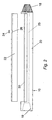
- a downhole tool 10 is shown in Fig. 2, and which is intended for inclusion in a string (not shown), such as a drill string made up of a number of drill pipes, where the string is inserted into a borehole 3 (see Fig. 1) to be drilled by a drilling rig/platform A.
- a string such as a drill string made up of a number of drill pipes, where the string is inserted into a borehole 3 (see Fig. 1) to be drilled by a drilling rig/platform A.
- the tool 10 comprises a body 20, which has a tapered screw thread pin connection 18 at one end and a tapered screw thread box connection 19 at the other end, for inclusion in a drill string in a conventional manner.
- the body 20 also comprises a throughbore 25, which is shown in dotted phantom lines, and which is in fluid communication with the pin 18 and box 19 connections, thus allowing fluid, such as conventional drilling fluid, to flow through the body 20.
- the lower half of the body 20 as shown in Fig. 2 is in the form of a standard tubular member, such as a drill pipe, and thus has a semi-circular outer circumference which is of the same diameter as the circular outer circumference of the box connection 19.
- the outer surface diameter of the box connection 19, and the semi-circular outer surface diameter of the lower half of the body 20, is 203.2mm (8 inches) and the inner diameter of the throughbore 25 is 73mm (27 ⁇ 8 inches), which provides a side wall thickness of the lower half of the body 20 of 65.1mm (2 9 / 16 inches).
- a length, which is semi-circular in cross-section, of the upper half of the body 20 shown in Fig. 2 has been removed, although a semi-circular side wall portion 30 of the body 20 remains, thus ensuring that there is no fluid leak path from the throughbore 25 through the sidewall portion 30.
- the sidewall portion 30 has a thickness of 12.7mm (1 ⁇ 2 inch).
- a cover 22 is shown in Fig. 2 and has a semi-circular cross-section of the same outer diameter as that of the lower half of the body 20 (that is 203.2mm (8 inches)).
- the sidewall thickness of the cover 22 is 12.7mm (1 ⁇ 2 inch).
- the cover 22 is fitted onto the upper half of the body 20 as shown in Fig. 2, such that the outer circumference of the cover 22 is in line with the outer circumference of the pin connection 19. Therefore, there is a cavity formed between the inner circumference of the cover 22 and the outer circumference of the upper half of the body 20 as shown in Fig. 2.
- the cross-sectional radius of the cavity 32 is 41.3mm (15 ⁇ 8 inch).
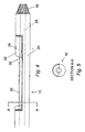
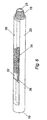
- the cover 22 is secured to the upper half of the body 20, as shown in Figs. 4, 5 and 6, and preferably the cover 22 is welded to the body 20.
- the cover 22 is formed from same the material removed from the body 20 to form the upper half of the body 20.
- An aperture 26 having a 38.1mm (11 ⁇ 2 inch) diameter is formed through the sidewall of the cover 22, and in use, the aperture 26 is obturated by a plug 24.
- the centre of mass of the body 20 through the cross-section shown in Fig. 5 does not coincide with the longitudinal axis of the downhole tool 10, since the lower half of the body 20 will have a greater collective mass than the upper half of the body 20.
- the collective mass of the upper half of the body 20 can be increased by inserting a filling material 34 into the cavity 30 through the aperture 26.
- a suitable filling material is shown in Fig. 6 as a number of 1 inch diameter steel balls, collectively designated as 34.
- the centre of mass of the body 20 can be altered.
- the steel balls 34 can optionally be secured within the cavity 32 by attaching a permanent magnet 36 to the outer surface of the side wall portion 30.
- the length, depth and width of the material removed from the upper half of the body 20 to form the side wall portion 30, the cover 22, and the resulting cavity 32 can be varied. Further, the number of one inch diameter steel balls 34 inserted into the cavity 32 can be varied, as can the location at which the downhole tool 10 is included in the string, depending on the formation through which it is required to be drilled.
- the body 20 when the body 20 is rotated, within the drill string, a vibratory action will be produced, since the downhole tool 10 will be rotating out of balance. Depending on the aforementioned variables, this vibratory action will tend to counterbalance the out of balance rotation of the drill bit, and thus reduce or preferably eliminate the variation of the drill bit from its intended path.
- the vibratory motion produced by the body 20 can be tuned to values chosen to counteract vibration or deviation of the string from its intended path. Accordingly, by reducing the vibration imparted to the end of the drill string by the out of balance rotation of the drill bit, the spiralling or helical action of the drill bit is reduced or optimally eliminated.
- the invention has the advantage that by providing a cavity 32 so that the centre of mass of a cross-section of the body 20 does not coincide with that of the downhole tool 10, or that of the string, the outer circumference of the body 20 has no upsets, and thus is flush with the outer circumference of the drill string.
- the cavity can be filled with filling material with a different density than the material forming the tool 10.
- the filling material can be a denser material such as lead.
- more than one cavity can be formed in the same portion of the tool 10, so as to allow increased control of variation of the string's path.
Landscapes
- Engineering & Computer Science (AREA)
- Geology (AREA)
- Life Sciences & Earth Sciences (AREA)
- Mining & Mineral Resources (AREA)
- Environmental & Geological Engineering (AREA)
- Fluid Mechanics (AREA)
- Physics & Mathematics (AREA)
- General Life Sciences & Earth Sciences (AREA)
- Geochemistry & Mineralogy (AREA)
- Mechanical Engineering (AREA)
- Earth Drilling (AREA)
- Perforating, Stamping-Out Or Severing By Means Other Than Cutting (AREA)
- Drilling And Exploitation, And Mining Machines And Methods (AREA)
- Drilling And Boring (AREA)
Claims (24)
- Eine Vorrichtung (10) zum Einschluss in einem Strang, der eine Längsachse und einen an einem Ende befindlichen Bohrmeißel aufweist, wobei die Vorrichtung (10) einen Körper (20) mit einer Längsachse, die mit der Längsachse des Strangs im Wesentlichen koaxial ist, beinhaltet, wobei ein Abschnitt (30) des Körpers (20) einen Querschnitt aufweist, wobei der Massenschwerpunkt des Körpers (20) auf diesen Querschnitt von der Längsachse des Strangs versetzt ist, wobei die Drehung des Abschnitts (30) des Körpers (20) um seine Längsachse eine Schwingungsbewegung durch den Abschnitt (30) des Körpers (20) erzeugt, um der Schwingung oder Ablenkung des Strangs von seiner geplanten Bahn entgegenzuwirken, dadurch gekennzeichnet, dass die Schwingungsbewegung durch das Ändern der Verteilung und/oder der Position und/oder der Größe der Masse in dem Abschnitt (30) des Körpers (20) abgestimmt werden kann, indem ein oder mehrere Stützmaterialelement(e) (34) aus dem Körper (20) bewegt, eingeführt oder entfernt wird/werden, wobei die Stützmaterialelemente (34) an dem Körper (20) lösbar befestigt sind.
- Vorrichtung (10) gemäß Anspruch 1, wobei die Versetzung des Massenschwerpunkts des Körpers (20) dadurch bereitgestellt ist, dass der Körper (20) ferner einen Hohlraum (32), der einen Durchlass aufweist, beinhaltet.
- Vorrichtung (10) gemäß Anspruch 2, wobei der Körper ferner einen Abdeckungsabschnitt (22), der zum Verschließen des Durchlasses des Hohlraums (32) angepasst ist, beinhaltet.
- Vorrichtung (10) gemäß einem der vorhergehenden Ansprüche, wobei die Masse des Körpers (20) auf diesem Querschnitt so verteilt ist, dass eine Hälfte des Querschnitts eine niedrigere Masse als die andere Hälfte des Querschnitts aufweist.
- Vorrichtung (10) gemäß einem der vorhergehenden Ansprüche, wobei der Körper (20) eine röhrenförmige Komponente (20) ist.
- Vorrichtung (10) gemäß Anspruch 5, wobei die röhrenförmige Komponente (20) eine Durchgangsbohrung (25) beinhaltet, die mit einer Durchgangsbohrung des Strangs in Verbindung steht.
- Vorrichtung (10) gemäß einem der Ansprüche 5 oder 6, wobei der Abschnitt (30) der röhrenförmigen Komponente (20) einen nicht einheitlichen röhrenförmigen Querschnitt beinhaltet.
- Vorrichtung (10) gemäß Anspruch 2 oder gemäß einem der Ansprüche 3 bis 7, wenn von Anspruch 2 abhängig, wobei der Hohlraum (32) entlang einer Länge der Längsachse der röhrenförmigen Komponente (20) gebildet ist.
- Vorrichtung (10) gemäß Anspruch 2 oder gemäß einem der Ansprüche 3 bis 8, wenn von Anspruch 2 abhängig, wobei die Stützmaterialelemente (34) in den Hohlraum (32) eingeführt oder aus dem Hohlraum entfernt werden, so dass der Massenschwerpunkt der röhrenförmigen Komponente (20) variiert wird.
- Vorrichtung (10) gemäß Anspruch 9, wobei eine Bewegung der Stützmaterialelemente (34) innerhalb des Hohlraums (32) verhindert wird.
- Vorrichtung (10) gemäß Anspruch 10, wobei die Bewegung der Stützmaterialelemente (34) in dem Hohlraum (32) durch eine Magnetkraft verhindert wird.
- Vorrichtung (10) gemäß Anspruch 3 oder gemäß einem der Ansprüche 4 bis 11, wenn von Anspruch 3 abhängig, wobei der Hohlraum (32) durch das Entfernen des Abdeckungsabschnitts (22) aus der röhrenförmigen Komponente (20) und das Entfernen von Material aus mindestens entweder der röhrenförmigen Komponente (20) oder dem Abdeckungsabschnitt (22) gebildet wird.
- Vorrichtung (10) gemäß Anspruch 3 oder gemäß einem der Ansprüche 4 bis 12, wenn von Anspruch 3 abhängig, wobei der Abdeckungsabschnitt (22) auf der röhrenförmigen Komponente (20) wieder platziert wird, so dass der Hohlraum (32) in dem Zwischenraum zwischen der röhrenförmigen Komponente (20) und dem Abdeckungsabschnitt (22) gebildet wird.
- Vorrichtung (10) gemäß Anspruch 3 oder gemäß einem der Ansprüche 4 bis 12, wenn von Anspruch 3 abhängig, wobei der Abdeckungsabschnitt (22) eine Öffnung (26) umfasst, um Zugang zu dem Hohlraum (32) zu ermöglichen.
- Vorrichtung (10) gemäß Anspruch 14, wobei es die Öffnung (26) ermöglicht, die Stützmaterialelemente (34) in den Hohlraum (32) einzuführen oder aus diesem zu entfernen.
- Vorrichtung (10) gemäß einem der Ansprüche 14 oder 15, wobei die Vorrichtung (10) ferner eine Verschlusseinrichtung (24) beinhaltet, um das Abdichten der Öffnung (26) zu ermöglichen.
- Vorrichtung (10) gemäß einem der Ansprüche 10 oder 14, wobei der Abdeckungsabschnitt (22) auf der röhrenförmigen Komponente (20) wieder plaziert wird und an der röhrenförmigen Komponente (20) befestigt werden kann.
- Vorrichtung (10) gemäß Anspruch 13 oder gemäß einem der Ansprüche 14 bis 17, wenn von Anspruch 13 abhängig, wobei der Abdeckungsabschnitt (22) dadurch an der röhrenförmigen Komponente (20) befestigt ist, dass er daran angeschweißt ist.
- Ein Verfahren zum Vermindern der Abweichung eines Bohrmeißels von seiner geplanten Bahn (1) in einem Bohrloch, bei dem der Bohrmeißel mit einem Ende eines Strangs, der eine Längsachse aufweist, gekoppelt ist, wobei das Verfahren Folgendes beinhaltet: das Einschließen eines Körpers (20) in dem Strang, wobei ein Abschnitt (30) des Körpers (20) einen Querschnitt aufweist, wobei der Massenschwerpunkt des Körpers (20) auf diesem Querschnitt von der Längsachse des Strangs versetzt ist; das Einführen des Strangs in ein Bohrloch; wobei eine Drehung des Abschnitts (30) des Körpers (20) um seine Längsachse eine Schwingungsbewegung des Abschnitts (30) des Körpers (20) erzeugt, um der Schwingung oder Ablenkung des Strangs von seiner geplanten Bahn entgegenzuwirken, gekennzeichnet durch das Abstimmen der Schwingungsbewegung, indem die Verteilung und/oder die Position und/oder die Größe der Masse in dem Abschnitt (30) des Körpers (20) geändert wird, indem ein oder mehrere Stützmaterialelement(e) (34) aus dem Körper (20) bewegt, eingeführt oder entfernt wird/werden, wobei die Stützmaterialelemente (34) an dem Körper (20) lösbar befestigt sind.
- Verfahren gemäß Anspruch 19, wobei der Abschnitt des Körpers einen Hohlraum (32) beinhaltet.
- Verfahren gemäß Anspruch 20, wobei der Hohlraum (32) mit einem Abdeckungsabschnitt (22) abgedeckt ist.
- Verfahren gemäß einem der Ansprüche 19 bis 21, wobei die Masse des Körpers (20) auf diesem Querschnitt so verteilt ist, dass eine Hälfte des Querschnitts eine niedrigere Masse als die andere Hälfte des Querschnitts aufweist.
- Verfahren gemäß einem der Ansprüche 20 oder 21 oder gemäß Anspruch 22, wenn von einem der Ansprüche 20 oder 21 abhängig, wobei der Körper (20) eine röhrenförmigen Komponente (20) ist und der Hohlraum (32) entlang einer Länge der Längsachse der röhrenförmigen Komponente (20) gebildet ist.
- Verfahren gemäß Anspruch 20 oder gemäß einem der Ansprüche 21 bis 23, wenn von Anspruch 20 abhängig, wobei das eine oder die mehreren Stützmaterialelement(e) (34) in den Hohlraum (32) eingeführt werden, so dass der Massenschwerpunkt der röhrenförmigen Komponente (20) variiert wird.
Applications Claiming Priority (7)
| Application Number | Priority Date | Filing Date | Title |
|---|---|---|---|
| US82875397A | 1997-03-24 | 1997-03-24 | |
| US828753 | 1997-03-24 | ||
| US6914697 | 1997-03-24 | ||
| US69146 | 1997-03-24 | ||
| GBGB9725740.6A GB9725740D0 (en) | 1997-03-24 | 1997-12-05 | Apparatus and a method for use downhole |
| GB9725740 | 1997-12-05 | ||
| PCT/GB1998/000739 WO1998042944A1 (en) | 1997-03-24 | 1998-03-24 | Apparatus and a method for drilling boreholes |
Publications (2)
| Publication Number | Publication Date |
|---|---|
| EP0901560A1 EP0901560A1 (de) | 1999-03-17 |
| EP0901560B1 true EP0901560B1 (de) | 2005-10-26 |
Family
ID=27269125
Family Applications (1)
| Application Number | Title | Priority Date | Filing Date |
|---|---|---|---|
| EP98912587A Expired - Lifetime EP0901560B1 (de) | 1997-03-24 | 1998-03-24 | Vorrichtung und verfahren zum bohren |
Country Status (9)
| Country | Link |
|---|---|
| EP (1) | EP0901560B1 (de) |
| AT (1) | ATE307954T1 (de) |
| AU (1) | AU6737198A (de) |
| CA (1) | CA2255750A1 (de) |
| DE (1) | DE69832018D1 (de) |
| DK (1) | DK0901560T3 (de) |
| GB (1) | GB9725740D0 (de) |
| NO (1) | NO985452L (de) |
| WO (1) | WO1998042944A1 (de) |
Families Citing this family (1)
| Publication number | Priority date | Publication date | Assignee | Title |
|---|---|---|---|---|
| US7066284B2 (en) | 2001-11-14 | 2006-06-27 | Halliburton Energy Services, Inc. | Method and apparatus for a monodiameter wellbore, monodiameter casing, monobore, and/or monowell |
Family Cites Families (17)
| Publication number | Priority date | Publication date | Assignee | Title |
|---|---|---|---|---|
| US2316409A (en) * | 1941-12-05 | 1943-04-13 | Lloyd R Downing | Oil well straightener |
| US3391749A (en) * | 1966-06-06 | 1968-07-09 | Land And Marine Rental Company | Method and apparatus for drilling straight wells |
| FR2083938A5 (de) * | 1970-03-26 | 1971-12-17 | Werkzeugbau Gmbh | |
| GB1483789A (en) * | 1974-11-07 | 1977-08-24 | Amoco Prod Co | Drilling tool for the directional drilling of boreholes in the earth |
| US4190122A (en) * | 1978-03-22 | 1980-02-26 | Arnold James F | Spaced weight relieved drill collar string |
| GB2052609A (en) * | 1979-06-15 | 1981-01-28 | Nl Industries Inc | Well deviation control tool and method of manufacture thereof |
| US4438810A (en) * | 1981-10-26 | 1984-03-27 | Dresser Industries, Inc. | Apparatus for decentralizing and orienting a well logging or perforating instrument |
| US4623026A (en) * | 1982-06-03 | 1986-11-18 | Kemp Billy W | Method and apparatus of a self-aligning sleeve for the correction of the direction of deviated boreholes |
| US4493380A (en) * | 1982-09-29 | 1985-01-15 | Kenneth A. Freeman | Hydraulic straight hole drill collar |
| US4770258A (en) * | 1987-04-27 | 1988-09-13 | Falgout Sr Thomas E | Well deviation control tool |
| US4771830A (en) * | 1987-05-01 | 1988-09-20 | Schlumberger Technology Corp. | Apparatus for positioning well tools in deviated well bores |
| US4982802A (en) * | 1989-11-22 | 1991-01-08 | Amoco Corporation | Method for stabilizing a rotary drill string and drill bit |
| US5220963A (en) * | 1989-12-22 | 1993-06-22 | Patton Consulting, Inc. | System for controlled drilling of boreholes along planned profile |
| US4995466A (en) * | 1989-12-22 | 1991-02-26 | Snow Jr Roy W | Method and device for stabilizing the path of a drilling tool |
| US5040619A (en) * | 1990-04-12 | 1991-08-20 | Halliburton Logging Services, Inc. | Wireline supported perforating gun enabling oriented perforations |
| DE4225009C2 (de) * | 1992-07-29 | 1996-09-05 | Tanke Oil Field Dev Gmbh | Verfahren zum Beseitigen einer Bohrlochneigung gegenüber der Vertikalen bei Erdbohrungen |
| CA2159886A1 (en) * | 1995-10-04 | 1997-04-05 | Ken Poffenroth | Drill stabilizer |
-
1997
- 1997-12-05 GB GBGB9725740.6A patent/GB9725740D0/en not_active Ceased
-
1998
- 1998-03-24 DK DK98912587T patent/DK0901560T3/da active
- 1998-03-24 AT AT98912587T patent/ATE307954T1/de not_active IP Right Cessation
- 1998-03-24 EP EP98912587A patent/EP0901560B1/de not_active Expired - Lifetime
- 1998-03-24 AU AU67371/98A patent/AU6737198A/en not_active Abandoned
- 1998-03-24 CA CA002255750A patent/CA2255750A1/en not_active Abandoned
- 1998-03-24 WO PCT/GB1998/000739 patent/WO1998042944A1/en not_active Ceased
- 1998-03-24 DE DE69832018T patent/DE69832018D1/de not_active Expired - Lifetime
- 1998-11-23 NO NO985452A patent/NO985452L/no not_active Application Discontinuation
Also Published As
| Publication number | Publication date |
|---|---|
| CA2255750A1 (en) | 1998-10-01 |
| AU6737198A (en) | 1998-10-20 |
| NO985452L (no) | 1999-01-22 |
| DK0901560T3 (da) | 2006-03-13 |
| EP0901560A1 (de) | 1999-03-17 |
| GB9725740D0 (en) | 1998-02-04 |
| NO985452D0 (no) | 1998-11-23 |
| WO1998042944A1 (en) | 1998-10-01 |
| ATE307954T1 (de) | 2005-11-15 |
| DE69832018D1 (de) | 2005-12-01 |
Similar Documents
| Publication | Publication Date | Title |
|---|---|---|
| US20030141112A1 (en) | Method and apparatus for drilling wells | |
| US4635738A (en) | Drill bit | |
| US4739843A (en) | Apparatus for lateral drilling in oil and gas wells | |
| US4552232A (en) | Drill-bit with full offset cutter bodies | |
| CN1633542B (zh) | 探测器壳体 | |
| US5220964A (en) | Downhole compaction and stabilization back reamer and drill bit | |
| EP0395572A1 (de) | Zweirollenmeissel mit nicht gegenüberliegenden Kegelrollen | |
| CA1166629A (en) | Rock drill | |
| DK157212B (da) | Underjordisk motor til boring af borehuller | |
| CA2159873A1 (en) | Drill Bit with Protruding Insert Stabilizers | |
| CA2307627C (en) | Mill for use in a wellbore and method of milling | |
| CA2081806A1 (en) | Apparatus for drilling a curved subterranean borehole | |
| EP1402144A1 (de) | Richtbohrwerkzeug | |
| BRPI1008480B1 (pt) | broca de perfuração, aparelho para uso em um furo de poço, método de fazer uma broca de perfuração e método de perfuração de um furo de poço | |
| US5099931A (en) | Method and apparatus for optional straight hole drilling or directional drilling in earth formations | |
| US7806204B2 (en) | Sonic drill rod with external surface features | |
| CA2255288C (en) | Apparatus and method for stabilized downhole drilling motor | |
| CA1086295A (en) | Arrangement for guiding a bore-crown or bit along a given path | |
| US4793740A (en) | Drilling system | |
| CA2387568C (en) | Drill bit with eccentric body | |
| EP0901560B1 (de) | Vorrichtung und verfahren zum bohren | |
| US5423388A (en) | Direction controllable subsurface borehole tool | |
| EP1811125B1 (de) | Bohrlochräumer | |
| US2309791A (en) | Method and apparatus for cementing wells | |
| EP1811126A1 (de) | Konischer Bohrlochräumer |
Legal Events
| Date | Code | Title | Description |
|---|---|---|---|
| PUAI | Public reference made under article 153(3) epc to a published international application that has entered the european phase |
Free format text: ORIGINAL CODE: 0009012 |
|
| 17P | Request for examination filed |
Effective date: 19981120 |
|
| AK | Designated contracting states |
Kind code of ref document: A1 Designated state(s): AT BE DE DK ES FR GB GR IE IT NL PT |
|
| 17Q | First examination report despatched |
Effective date: 20021018 |
|
| GRAP | Despatch of communication of intention to grant a patent |
Free format text: ORIGINAL CODE: EPIDOSNIGR1 |
|
| GRAS | Grant fee paid |
Free format text: ORIGINAL CODE: EPIDOSNIGR3 |
|
| GRAA | (expected) grant |
Free format text: ORIGINAL CODE: 0009210 |
|
| AK | Designated contracting states |
Kind code of ref document: B1 Designated state(s): AT BE DE DK ES FR GB GR IE IT NL PT |
|
| PG25 | Lapsed in a contracting state [announced via postgrant information from national office to epo] |
Ref country code: BE Free format text: LAPSE BECAUSE OF FAILURE TO SUBMIT A TRANSLATION OF THE DESCRIPTION OR TO PAY THE FEE WITHIN THE PRESCRIBED TIME-LIMIT Effective date: 20051026 Ref country code: AT Free format text: LAPSE BECAUSE OF FAILURE TO SUBMIT A TRANSLATION OF THE DESCRIPTION OR TO PAY THE FEE WITHIN THE PRESCRIBED TIME-LIMIT Effective date: 20051026 |
|
| REG | Reference to a national code |
Ref country code: GB Ref legal event code: FG4D |
|
| REG | Reference to a national code |
Ref country code: IE Ref legal event code: FG4D |
|
| REF | Corresponds to: |
Ref document number: 69832018 Country of ref document: DE Date of ref document: 20051201 Kind code of ref document: P |
|
| PG25 | Lapsed in a contracting state [announced via postgrant information from national office to epo] |
Ref country code: GR Free format text: LAPSE BECAUSE OF FAILURE TO SUBMIT A TRANSLATION OF THE DESCRIPTION OR TO PAY THE FEE WITHIN THE PRESCRIBED TIME-LIMIT Effective date: 20060126 |
|
| PG25 | Lapsed in a contracting state [announced via postgrant information from national office to epo] |
Ref country code: DE Free format text: LAPSE BECAUSE OF FAILURE TO SUBMIT A TRANSLATION OF THE DESCRIPTION OR TO PAY THE FEE WITHIN THE PRESCRIBED TIME-LIMIT Effective date: 20060127 |
|
| PG25 | Lapsed in a contracting state [announced via postgrant information from national office to epo] |
Ref country code: ES Free format text: LAPSE BECAUSE OF FAILURE TO SUBMIT A TRANSLATION OF THE DESCRIPTION OR TO PAY THE FEE WITHIN THE PRESCRIBED TIME-LIMIT Effective date: 20060206 |
|
| REG | Reference to a national code |
Ref country code: DK Ref legal event code: T3 |
|
| PG25 | Lapsed in a contracting state [announced via postgrant information from national office to epo] |
Ref country code: IE Free format text: LAPSE BECAUSE OF NON-PAYMENT OF DUE FEES Effective date: 20060324 |
|
| PG25 | Lapsed in a contracting state [announced via postgrant information from national office to epo] |
Ref country code: PT Free format text: LAPSE BECAUSE OF FAILURE TO SUBMIT A TRANSLATION OF THE DESCRIPTION OR TO PAY THE FEE WITHIN THE PRESCRIBED TIME-LIMIT Effective date: 20060327 |
|
| PLBE | No opposition filed within time limit |
Free format text: ORIGINAL CODE: 0009261 |
|
| STAA | Information on the status of an ep patent application or granted ep patent |
Free format text: STATUS: NO OPPOSITION FILED WITHIN TIME LIMIT |
|
| 26N | No opposition filed |
Effective date: 20060727 |
|
| EN | Fr: translation not filed | ||
| PG25 | Lapsed in a contracting state [announced via postgrant information from national office to epo] |
Ref country code: FR Free format text: LAPSE BECAUSE OF FAILURE TO SUBMIT A TRANSLATION OF THE DESCRIPTION OR TO PAY THE FEE WITHIN THE PRESCRIBED TIME-LIMIT Effective date: 20061215 |
|
| REG | Reference to a national code |
Ref country code: IE Ref legal event code: MM4A |
|
| PG25 | Lapsed in a contracting state [announced via postgrant information from national office to epo] |
Ref country code: FR Free format text: LAPSE BECAUSE OF FAILURE TO SUBMIT A TRANSLATION OF THE DESCRIPTION OR TO PAY THE FEE WITHIN THE PRESCRIBED TIME-LIMIT Effective date: 20051026 |
|
| PG25 | Lapsed in a contracting state [announced via postgrant information from national office to epo] |
Ref country code: IT Free format text: LAPSE BECAUSE OF NON-PAYMENT OF DUE FEES Effective date: 20090324 |
|
| PGRI | Patent reinstated in contracting state [announced from national office to epo] |
Ref country code: IT Effective date: 20110616 |
|
| PGFP | Annual fee paid to national office [announced via postgrant information from national office to epo] |
Ref country code: DK Payment date: 20160317 Year of fee payment: 19 Ref country code: NL Payment date: 20160316 Year of fee payment: 19 |
|
| PGFP | Annual fee paid to national office [announced via postgrant information from national office to epo] |
Ref country code: GB Payment date: 20160318 Year of fee payment: 19 |
|
| PGFP | Annual fee paid to national office [announced via postgrant information from national office to epo] |
Ref country code: IT Payment date: 20160329 Year of fee payment: 19 |
|
| REG | Reference to a national code |
Ref country code: DK Ref legal event code: EBP Effective date: 20170331 |
|
| REG | Reference to a national code |
Ref country code: NL Ref legal event code: MM Effective date: 20170401 |
|
| GBPC | Gb: european patent ceased through non-payment of renewal fee |
Effective date: 20170324 |
|
| PG25 | Lapsed in a contracting state [announced via postgrant information from national office to epo] |
Ref country code: NL Free format text: LAPSE BECAUSE OF NON-PAYMENT OF DUE FEES Effective date: 20170401 |
|
| PG25 | Lapsed in a contracting state [announced via postgrant information from national office to epo] |
Ref country code: IT Free format text: LAPSE BECAUSE OF NON-PAYMENT OF DUE FEES Effective date: 20170324 Ref country code: GB Free format text: LAPSE BECAUSE OF NON-PAYMENT OF DUE FEES Effective date: 20170324 |
|
| PG25 | Lapsed in a contracting state [announced via postgrant information from national office to epo] |
Ref country code: DK Free format text: LAPSE BECAUSE OF NON-PAYMENT OF DUE FEES Effective date: 20170331 |