EP0901569B1 - Steuersystem für einen abgasturbolader mit veränderbarer geometrie - Google Patents
Steuersystem für einen abgasturbolader mit veränderbarer geometrie Download PDFInfo
- Publication number
- EP0901569B1 EP0901569B1 EP97925138A EP97925138A EP0901569B1 EP 0901569 B1 EP0901569 B1 EP 0901569B1 EP 97925138 A EP97925138 A EP 97925138A EP 97925138 A EP97925138 A EP 97925138A EP 0901569 B1 EP0901569 B1 EP 0901569B1
- Authority
- EP
- European Patent Office
- Prior art keywords
- engine
- variable geometry
- turbocharger
- control
- pressure
- Prior art date
- Legal status (The legal status is an assumption and is not a legal conclusion. Google has not performed a legal analysis and makes no representation as to the accuracy of the status listed.)
- Expired - Lifetime
Links
Images
Classifications
-
- F—MECHANICAL ENGINEERING; LIGHTING; HEATING; WEAPONS; BLASTING
- F02—COMBUSTION ENGINES; HOT-GAS OR COMBUSTION-PRODUCT ENGINE PLANTS
- F02D—CONTROLLING COMBUSTION ENGINES
- F02D41/00—Electrical control of supply of combustible mixture or its constituents
- F02D41/02—Circuit arrangements for generating control signals
- F02D41/14—Introducing closed-loop corrections
- F02D41/1438—Introducing closed-loop corrections using means for determining characteristics of the combustion gases; Sensors therefor
- F02D41/1444—Introducing closed-loop corrections using means for determining characteristics of the combustion gases; Sensors therefor characterised by the characteristics of the combustion gases
- F02D41/1448—Introducing closed-loop corrections using means for determining characteristics of the combustion gases; Sensors therefor characterised by the characteristics of the combustion gases the characteristics being an exhaust gas pressure
-
- F—MECHANICAL ENGINEERING; LIGHTING; HEATING; WEAPONS; BLASTING
- F02—COMBUSTION ENGINES; HOT-GAS OR COMBUSTION-PRODUCT ENGINE PLANTS
- F02B—INTERNAL-COMBUSTION PISTON ENGINES; COMBUSTION ENGINES IN GENERAL
- F02B37/00—Engines characterised by provision of pumps driven at least for part of the time by exhaust
- F02B37/12—Control of the pumps
- F02B37/24—Control of the pumps by using pumps or turbines with adjustable guide vanes
-
- F—MECHANICAL ENGINEERING; LIGHTING; HEATING; WEAPONS; BLASTING
- F02—COMBUSTION ENGINES; HOT-GAS OR COMBUSTION-PRODUCT ENGINE PLANTS
- F02D—CONTROLLING COMBUSTION ENGINES
- F02D41/00—Electrical control of supply of combustible mixture or its constituents
- F02D41/0002—Controlling intake air
- F02D41/0007—Controlling intake air for control of turbo-charged or super-charged engines
-
- F—MECHANICAL ENGINEERING; LIGHTING; HEATING; WEAPONS; BLASTING
- F02—COMBUSTION ENGINES; HOT-GAS OR COMBUSTION-PRODUCT ENGINE PLANTS
- F02D—CONTROLLING COMBUSTION ENGINES
- F02D41/00—Electrical control of supply of combustible mixture or its constituents
- F02D41/02—Circuit arrangements for generating control signals
- F02D41/14—Introducing closed-loop corrections
- F02D41/1401—Introducing closed-loop corrections characterised by the control or regulation method
- F02D2041/1409—Introducing closed-loop corrections characterised by the control or regulation method using at least a proportional, integral or derivative controller
-
- F—MECHANICAL ENGINEERING; LIGHTING; HEATING; WEAPONS; BLASTING
- F02—COMBUSTION ENGINES; HOT-GAS OR COMBUSTION-PRODUCT ENGINE PLANTS
- F02D—CONTROLLING COMBUSTION ENGINES
- F02D41/00—Electrical control of supply of combustible mixture or its constituents
- F02D41/02—Circuit arrangements for generating control signals
- F02D41/14—Introducing closed-loop corrections
- F02D41/1401—Introducing closed-loop corrections characterised by the control or regulation method
- F02D2041/1413—Controller structures or design
- F02D2041/1418—Several control loops, either as alternatives or simultaneous
-
- F—MECHANICAL ENGINEERING; LIGHTING; HEATING; WEAPONS; BLASTING
- F02—COMBUSTION ENGINES; HOT-GAS OR COMBUSTION-PRODUCT ENGINE PLANTS
- F02D—CONTROLLING COMBUSTION ENGINES
- F02D41/00—Electrical control of supply of combustible mixture or its constituents
- F02D41/02—Circuit arrangements for generating control signals
- F02D41/14—Introducing closed-loop corrections
- F02D41/1401—Introducing closed-loop corrections characterised by the control or regulation method
- F02D2041/1413—Controller structures or design
- F02D2041/1422—Variable gain or coefficients
-
- Y—GENERAL TAGGING OF NEW TECHNOLOGICAL DEVELOPMENTS; GENERAL TAGGING OF CROSS-SECTIONAL TECHNOLOGIES SPANNING OVER SEVERAL SECTIONS OF THE IPC; TECHNICAL SUBJECTS COVERED BY FORMER USPC CROSS-REFERENCE ART COLLECTIONS [XRACs] AND DIGESTS
- Y02—TECHNOLOGIES OR APPLICATIONS FOR MITIGATION OR ADAPTATION AGAINST CLIMATE CHANGE
- Y02T—CLIMATE CHANGE MITIGATION TECHNOLOGIES RELATED TO TRANSPORTATION
- Y02T10/00—Road transport of goods or passengers
- Y02T10/10—Internal combustion engine [ICE] based vehicles
- Y02T10/12—Improving ICE efficiencies
Definitions
- the present invention relates to a control system for a variable geometry turbocharger.
- Turbochargers comprise a turbine driven by exhaust gas delivered to an exhaust gas inlet of the turbocharger from an engine exhaust manifold.
- the turbine drives a compressor which delivers air to an engine intake manifold via an air outlet of the turbocharger.
- physically displaceable components are located in the exhaust gas inlet of the turbocharger so that the geometry of the inlet can be adjusted to control the exhaust gas pressure upstream of the turbine and the speed at which the exhaust gas flows through the turbine. This in turn affects the speed of rotation of the turbine, and hence the speed of rotation of the associated compressor.
- Generally variable geometry mechanisms in turbochargers are displaced in order to appropriately modulate the intake manifold pressure of the engine to optimise engine running conditions.
- Electronic variable geometry turbocharger control devices which receive input signals representing different engine operation parameters and generate a control signal which is used to control an actuator which in turn controls the geometry of the variable mechanism so as to achieve desired running conditions.
- Most of the known control devices are designed to maintain a desired engine intake manifold pressure or density as a function of engine speed and fuel rate.
- the control signal may also be modified to take into account for example ambient temperature and pressure, charge air temperature, turbocharger rotational speed and throttle demand.
- the known devices may define closed loop control systems in which a control signal is generated by comparing a direct measurement of the intake manifold pressure with a desired value of this parameter, or by comparing a calculated actual inlet manifold density with a desired value of this parameter. The magnitude of the difference revealed by the comparison is used to derive a control signal which determines the displacement of the variable geometry mechanism.
- Such devices are satisfactory for steady or quasi-steady state operation, but do not operate well in rapidly changing transient conditions. For example, if there is a sudden increase in the demanded intake manifold pressure, perhaps as a result of a large change in power demand, the natural action of the control device is to drive the control signal in such a way as to reduce the turbine inlet area in order to increase intake manifold pressure and density.
- variable geometry mechanism will probably reduce the turbine area to a minimum value very rapidly in order to increase the intake manifold pressure and density as rapidly as possibly, before increasing the turbine area again to some new quasi-steady state area as the new desired intake manifold pressure and density is approached.
- the exhaust manifold pressure rises much more rapidly than the intake manifold pressure as a result of the different time constants of the exhaust and intake systems. If this effect is not properly regulated, the end result is a large negative pressure differential across the engine, that is between the engine intake manifold and the engine exhaust manifold, and this causes a large reduction in engine volumetric efficiency.
- variable geometry turbochargers It is also known in variable geometry turbochargers to modulate the engine braking power by acting on the exhaust flow, for example by restricting the exhaust flow.
- the known engine braking control systems monitor several input signals representative of engine operating parameters and generate a control signal which is applied to an actuator of the variable geometry mechanism so as to achieve the desired braking power.
- the known systems are open loop however as no direct measurement of braking power is fed back to the controller. It is possible to cause damage to the engine if the variable geometry mechanism restricts the turbine inlet area too much so that an excessive exhaust manifold pressure is generated. Therefore current braking control devices using open loop control are always designed with wide safety margins to account for production variations, ambient pressure and temperature variations, and lifetime variations in the performance of the engine and turbocharger. The result of all these constraints is that engine braking power is significantly reduced as compared with what is potentially available.
- a closed loop control system for a variable geometry turbocharger having the features of the pre-characterizing portion of claim 1 is disclosed in German patent application NO. DE-A-3731320.
- a control system for a variable geometry turbocharger having a turbine driven by exhaust gas delivered to an exhaust gas inlet of the turbocharger from an engine exhaust manifold and a compressor driven by the turbine to deliver air to an engine intake manifold via an air outlet of the turbocharger, comprising means for monitoring a parameter which is a function of the pressure within the engine exhaust manifold, and closed loop control means for controlling the displacement of a variable geometry mechanism located upstream of the turbine to maintain the monitored parameter within predetermined limits, characterised in that the monitored parameter is a function of the difference between the pressures within the engine exhaust manifold and the engine intake manifold divided by either the pressure within the engine exhaust manifold or the pressure within the engine intake manifold.
- a control system for a variable geometry turbocharger having a turbine driven by exhaust gas delivered to an exhaust gas inlet of the turbocharger from an engine exhaust manifold and a compressor driven by the turbine to deliver air to an engine intake manifold via an air outlet of the turbocharger, comprising means for monitoring a parameter which is a function of the pressure within the engine exhaust manifold, and closed loop control means for controlling the displacement of a variable geometry mechanism located upstream of the turbine to maintain the monitored parameter within predetermined limits, characterised in that the monitored parameter is a function of the density of the gas within the exhaust gas manifold.
- the predetermined limit may be fixed, or may be derived from the engine operation conditions, for example engine speed and fuel rate.
- a switch may be provided to select either a first control signal intended to control the variable geometry mechanism to maintain a desired engine intake manifold pressure or density, or a second control signal intended to control a variable geometry mechanism to maintain the monitored parameter within the predetermined limits.
- the switch may be controlled in dependence upon whether or not the second signal exceeds the predetermined limits.
- the selection of either the first or second control signals may be overridden by a third control signal intended to reduce turbocharger speed if the turbocharger speed exceeds a predetermined limit, or by a fourth control signal intended to control the variable geometry mechanism to provide a desired exhaust manifold pressure during engine braking when the engine is in braking mode.
- the invention provides closed loop control of engine volumetric efficiency which enables the optimisation of engine performance through transient operating conditions and an appropriate response to transient conditions.
- the exhaust pressure can be used as a feedback signal to achieve optimised braking performance. Adverse effects on the engine can be avoided under all conditions. Thus the transient response of the engine and the engine braking power may be maximised without exceeding safety limits.
- the system also compensates for production variations, ambient pressure and temperature variations, and lifetime variations in the performance of the engine and turbocharger.
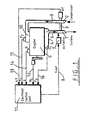
- variable geometry mechanism (not shown) is mounted adjacent the turbine 1.
- the invention is applicable to many different types of variable geometry turbocharger mechanisms, for example that described in published European patent specification No. 0342889. Whatever sort of variable geometry mechanism is used, in essence it is a displaceable mechanism located upstream of the turbine 1 to vary the flow area and thus velocity of a flow of exhaust gas which flows from an exhaust manifold 4 of an engine 5 via an exhaust gas inlet 6 of the turbocharger.
- variable geometry mechanism is displaceable by an actuator 7 controlled by a control signal S out on line 8, the displacement of the variable geometry mechanism determining the pressure within the inlet 6, and hence within the exhaust manifold 4, and the speed of the exhaust gas which impinges upon the turbine 1.
- the compressor wheel 2 drives ambient air through an air outlet 9 of the turbocharger to an engine intake manifold 10.
- the control signal S out is generated by an electronic control unit 11 which receives an input N E on line 12 which is representative of engine rpm, an input N T on line 13 which is indicative of the rpm of the compressor wheel 2, an input Q on line 14 which is indicative of the rate at which fuel is being delivered to the engine, an input P 2 on line 15 which is indicative of the pressure within the engine intake manifold, and an input P 3 on line 16 which is indicative of the pressure in the engine exhaust manifold.
- the signal S out is dependant upon the five input signals as described in greater detail with reference to Figure 2.
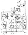
- the electronic control unit comprises four subcircuits 17, 18, 19 and 20.
- the subcircuit 17 as a conventional circuit which produces a first control signal output S P2 which is related to the intake manifold pressure P 2 .
- Circuit 18 produces a second control signal S ⁇ P which acts to limit the pressure differential across the engine when negative, that is the pressure differential between the intake manifold pressure P 2 and the exhaust manifold pressure P 3 .
- the circuit 19 produces a third control signal S NT which acts to limit the maximum rpm of the turbocharger.
- Circuit 20 produces a forth control signal S P3 which controls the actuator 7 when the system is in braking mode.
- Circuit 17 receives as inputs the engine speed signal N E and the fuel rate signal Q. These inputs address a look-up table schematically represented by box 21 to produce an output P 2DEM representative of the desired intake manifold pressure. This signal is compared in a comparator 22 with the intake manifold pressure P 2 , and the comparator 22 produces the difference output P 2DIFF . That difference output is applied to a signal conditioning circuit 23 the output of which is the first control signal S P2 .
- the first subcircuit 17 is of conventional form and in a conventional system the output S P2 would be directly applied to the actuator 7 so as to control the variable geometry mechanism.
- the circuit 18 receives as inputs the engine rpm signal N E , the fuelling quantity input Q, the intake manifold pressure signal P 2 and the exhaust manifold pressure signal P 3 .
- the engine rpm and fuel rate signals address a look-up table represented by box 24 the output ⁇ P MAX of which represents the maximum pressure differential which can be allowed without the volumetric efficiency of the engine being unduly reduced, that is reduced to an extent which would result in an unacceptable transient performance response.
- a comparator 25 produces an output ⁇ P representing the difference between the intake manifold pressure P 2 and the exhaust manifold pressure P 3 .
- the signals ⁇ P MAX and ⁇ P are applied to a comparator 26 which produces an output ⁇ P DIFF that is applied to a conventional PID circuit 27 and to a switch control circuit 28.
- the circuit 27 processes the difference value ⁇ P DIFF in a proportional term subcircuit 29, an integral term subcircuit 30, and a differential term subcircuit 31.
- the outputs of these three subcircuits are summed to produce the second control signal S ⁇ P .
- the circuit 28 controls a switch 32 and a switch 33.
- the switch 32 selects either the output of the subcircuit 17 or the output of the subcircuit 18 to form a signal S P on line 34.
- the switch 33 is provided in parallel with the integrator subcircuit 30 to prevent integrator saturation when the switch 32 selects the output of the subcircuit 17.
- the controller 28 connects the output of the subcircuit 17 to the line 34 except when the signal ⁇ P is greater than the signal ⁇ P MAX , that is except when ⁇ P DIFF is negative. Accordingly the output signal S P corresponds to the output S P2 of subcircuit 17 during normal steady state operation but is switched to the output S ⁇ P in the event of the pressure differential across the engine exceeding the predetermined limit represented by ⁇ P MAX .
- the subcircuit 19 is a conventional turbocharger rpm governor and receives the inputs N E and N T .
- a look-up table represented by box 35 is addressed by the engine rpm signal N E to produce an output N TMAX which is applied to a comparator 36.
- the other input to the comparator 36 is the signal N T such that the output N TDIFF of the comparator 36 represents the difference between the actual turbocharger rpm and the maximum desired turbocharger rpm.
- a signal conditioning circuit 37 produces a third control signal S NT which is applied to a switch 38 controlled by a controller 39 responsive to the output N TDIFF of the comparator 36.
- the switch 38 assumes the condition shown unless N T is greater than N TMAX , that is unless N TDIFF is negative.
- the fourth subcircuit 20 provides a fourth control signal output S P3 which is one input to a switch 40.
- the other input to the switch 40 is the signal S P output from the switch 32.
- the circuit 20 incorporates a look-up table represented by box 41 which is addressed by the engine rpm signal N E to produce an output P 3DEM to a comparator 42.
- the comparator 42 also receives the exhaust manifold pressure signal P 3 and produces an output P 3DIFF which is applied to a PID controller 43.
- the operation of the circuit 43 is similar to that of the controller 27 and will not be described further.
- the desired exhaust manifold pressure represented by the signal P 3DEM is predetermined to give the desired engine braking power without any safety limits of the engine being exceeded.
- the PID controller 43 ensures that the output S P3 when switched through to the actuator 7 is appropriate to limit the exhaust manifold pressure during braking to the signal P 3DEM.
- the output signal S P3 is isolated by the switch 40 and does not contribute to the overall control system.
- this is detected by a controller 44 which actuates the switch 40 so as to transfer the signal S P3 through to the switch 38.
- the output signal S out applied to the actuator 7 corresponds to the signal S NT if the turbocharger rpm limit is exceeded. If the turbocharger rpm limit is not exceeded, but the engine is in braking mode, the output signal S out corresponds to the signal S P3 from the fourth subcircuit 20. If the turbocharger rpm limit is not exceeded and the engine is not in braking mode, then the output signal S out corresponds to the output signal S P2 of the subcircuit 17 unless the pressure differential exceeds a predetermined limit, in which case the output signal S out corresponds to the output signal S ⁇ P from subcircuit 18.
- additional sensors may be provided to monitor additional parameters, for example ambient pressure and temperature, intake manifold temperature, and vehicle road speed.
- the ambient pressure and temperature and intake manifold temperature may be sensed to improve the performance of the first subcircuit 17.
- the road speed may be monitored to improve the performance of the engine braking subcircuit 20.
- the PID controllers 27 and 43 as shown in Figure 2 may be replaced by alternative standard processing circuits.
- the value ⁇ P representing the differential pressure across the engine may be calculated in a variety of different ways.
- the value ⁇ P may be taken to be the difference between the exhaust manifold pressure and the intake manifold pressure divided by either the exhaust manifold pressure or the intake manifold pressure.
- the value ⁇ P MAX that is the maximum allowed magnitude of the differential pressure ⁇ P, may be calculated in a variety of different ways. It will usually be a function of at least engine rpm N E and fuelling quantity, but for certain applications could be a simple constant value for all engine conditions.
- the switch 38 is actuated if the turbocharger rpm N T is greater than the maximum permitted turbocharger rpm.
- the switch 38 could be actuated on the basis of the relative sizes of the two control signals S and S NT .
- the output of the switch 38 will be selected always to correspond to whichever of the signals S and S NT is the smaller. If the relationship between the signal S ou t and the turbine area were reversed, then the output of the switch 38 would always be whichever of the signals S and S NT is the greater.
- the engine braking subcircuit 20 in the illustrated arrangement is responsive to the engine speed and exhaust manifold pressure. It may also be responsive to variations in the ambient pressure, the ambient temperature, the intake manifold temperature and a driver demand signal.
- the switch 32 will be actuated such that its output is connected to the signal S ⁇ P .
- the system will operate to control the turbocharger to maintain the differential pressure ⁇ P at the limit ⁇ P MAX .
- the switch 38 will return to its former condition.
- the switch 32 may be controlled on the basis of the relative magnitudes of the signals S ⁇ P and S P2 , the output of the switch 32 always corresponding to the lower of the signals S P2 and S ⁇ P for a turbocharger where an increase in control signal causes a reduction in turbine area.
- the circuit acts to maximise response of the air system and engine.
- the intake manifold pressure monitoring circuit 17 acts to reduce the turbine area as quickly as possible to give a rapid rate of increase to the intake manifold pressure. If the exhaust pressure rises too far however, that is to a point where the negative pressure differential across the engine (and hence the volumetric efficiency of the engine) would begin to fall significantly so as to cause a loss in performance, then the subcircuit 18 assumes control to maintain the negative pressure differential at the optimum value ⁇ P MAX which is chosen to allow the maximum rate of increase of the intake manifold pressure without significant loss of volumetric efficiency and load acceptance.
- the switch 40 is actuated and the variable geometry mechanism is then under the control of the engine braking subcircuit 20.
- the system is under full closed loop control at all times, and it is possible therefore to drastically reduce the errors associated with conventional open loop control systems and to allow braking powers up to the maximum potentially available.
- the turbocharger speed subcircuit 19 ensures that safe turbocharger rpms are never exceeded.
Landscapes
- Engineering & Computer Science (AREA)
- Chemical & Material Sciences (AREA)
- Combustion & Propulsion (AREA)
- Mechanical Engineering (AREA)
- General Engineering & Computer Science (AREA)
- Supercharger (AREA)
Claims (9)
- Steuersystem für einen Turbolader mit variabler Geometrie, der eine Turbine (1) hat, die durch Abgas angetrieben wird, das von einem Motorauspuffkrümmer (4) nach einem Abgaseinlaß (6) des Turboladers abgegeben wird, und der einen von der Turbine (1) angetriebenen Kompressor (2) hat, um Luft über einen Luftauslaß (9) des Turboladers nach einem Motoransaugkrümmer (10) abzugeben, aufweisend Mittel (11) zum Überwachen eines Parameters (ΔP), der eine Funktion des Drucks (P3) innerhalb des Motorauspuffkrümmers (4) ist, und Steuermittel (11) mit geschlossenem Kreis, zum Steuern der Verschiebung eines stromaufwärts von der Turbine (1) gelegenen Mechanismus mit variabler Geometrie, um den überwachten Parameter (ΔP) innerhalb vorgegebener Grenzen zu halten, dadurch gekennzeichnet, daß der überwachte Parameter (ΔP) eine Funktion der Differenz zwischen den Drücken (P3, P2) innerhalb des Motorauspuffkrümmers (4) und des Motoransaugkrümmers (10) geteilt durch den Druck innerhalb des Motorauspuffkrümmers (4) oder durch den Druck innerhalb des Motoransaugkrümmers (10) ist.
- Steuersystem gemäß Anspruch 1, wobei der überwachte Parameter (ΔP) eine Funktion der Differenz zwischen den Drücken (P3, P2) innerhalb des Motorauspuffkrümmers (4) und des Motoransaugkrümmers (10), geteilt durch den Druck innerhalb des Motorauspuffkrümmers (4) ist.
- Steuersystem gemäß Anspruch 1, wobei der überwachte Parameter eine Funktion der Differenz zwischen den Drücken (P3, P2) innerhalb des Motorauspuffkrümmers (4) und des Motoransaugkrümmers (10), geteilt durch den Druck innerhalb des Motoransaugkrümmers (10) ist.
- Steuersystem für einen Turbolader mit variabler Geometrie, der eine Turbine (1) hat, die durch Abgas angetrieben wird, das von einem Motorauspuffkrümmer (4) nach einem Abgaseinlaß (6) des Turboladers abgegeben wird, und der einen von der Turbine (1) angetriebenen Kompressor (2) hat, um Luft über einen Luftauslaß (9) des Turboladers nach einem Motoransaugkrümmer (10) abzugeben, aufweisend Mittel (11) zum Überwachen eines Parameters, der eine Funktion des Drucks (P3) innerhalb des Motorauspuffkrümmers (4) ist, und Steuermittel (11) mit geschlossenem Kreis, zum Steuern der Verschiebung eines stromaufwärts von der Turbine (1) gelegenen Mechanismus mit variabler Geometrie, um den überwachten Parameter innerhalb vorgegebener Grenzen zu halten, dadurch gekennzeichnet, daß der überwachte Parameter eine Funktion der Dichte des Gases innerhalb des Auspuffkrümmers (4) ist.
- Steuersystem gemäß irgendeinem vorhergehenden Anspruch, wobei die vorgegebene Grenze fest ist.
- Steuersystem gemäß irgendeinem der Ansprüche 1 bis 4, wobei die vorgegebene Grenze eine Funktion von mindestens der Motordrehzahl und der zugeführten Kraftstoffmenge ist.
- Steuersystem gemäß irgendeinem vorhergehenden Anspruch, aufweisend eine erste Schaltung (17) zum Erzeugen eines ersten Steuersignals (SP2), um den Mechanismus mit variabler Geometrie zu steuern, um einen gewünschten Motoransaugkrümmerdruck (P2) aufrechtzuerhalten, eine zweite Schaltung (18) zum Erzeugen eines zweiten Steuersignals (SΔP), um den Mechanismus mit variabler Geometrie zu steuern, um den überwachten Parameter (ΔP) innerhalb der vorgegebenen Grenzen zu halten, und einen Schalter (32), um dem Mechanismus mit variabler Geometrie in selektiver Weise das erste Signal (SP2) zuzuführen, wenn die vorgegebenen Grenzen nicht erreicht werden, und das zweite Signal (SΔP) zuzuführen, wenn die vorgegebenen Grenzen erreicht werden.
- Steuersystem gemäß Anspruch 7, aufweisend Mittel (19) zum Erzeugen eines dritten Steuersignals (SNT), um den Mechanismus mit variabler Geometrie zu steuern, um zu verhindern, daß die Turboladerdrehzahl eine vorgegebene Drehzahlgrenze überschreitet, und einen Schalter (38) zum selektiven Anlegen des dritten Steuersignals (SNT) an den Mechanismus mit variabler Geometrie, wenn die vorgegebene Drehzahlgrenze überschritten wird.
- Steuersystem gemäß Anspruch 7 oder 8, aufweisend Mittel (20) zum Erzeugen eines vierten Steuersignals (SP3), um den Mechanismus mit variabler Geometrie so zu steuern, daß während der Motorbremsung ein gewünschter Auspuffkrümmerdruck (P3) erhalten wird, und einen Schalter (40), um das vierte Signal (SP3) in selektiver Weise dem Mechanismus mit variabler Geometrie zuzuführen, wenn der Motor in dem Bremsmodus ist.
Applications Claiming Priority (3)
| Application Number | Priority Date | Filing Date | Title |
|---|---|---|---|
| GBGB9611015.0A GB9611015D0 (en) | 1996-05-25 | 1996-05-25 | Variable geometry turbocharger control |
| GB9611015 | 1996-05-25 | ||
| PCT/GB1997/001419 WO1997045633A1 (en) | 1996-05-25 | 1997-05-23 | Variable geometry turbocharger control system |
Publications (2)
| Publication Number | Publication Date |
|---|---|
| EP0901569A1 EP0901569A1 (de) | 1999-03-17 |
| EP0901569B1 true EP0901569B1 (de) | 2002-04-17 |
Family
ID=10794332
Family Applications (1)
| Application Number | Title | Priority Date | Filing Date |
|---|---|---|---|
| EP97925138A Expired - Lifetime EP0901569B1 (de) | 1996-05-25 | 1997-05-23 | Steuersystem für einen abgasturbolader mit veränderbarer geometrie |
Country Status (6)
| Country | Link |
|---|---|
| US (1) | US6718767B1 (de) |
| EP (1) | EP0901569B1 (de) |
| CN (1) | CN1081736C (de) |
| DE (1) | DE69712056T2 (de) |
| GB (1) | GB9611015D0 (de) |
| WO (1) | WO1997045633A1 (de) |
Cited By (1)
| Publication number | Priority date | Publication date | Assignee | Title |
|---|---|---|---|---|
| AT517033B1 (de) * | 2015-03-30 | 2018-06-15 | Avl List Gmbh | Verfahren zur regelung des betriebspunktes einer abgasturbine |
Families Citing this family (53)
| Publication number | Priority date | Publication date | Assignee | Title |
|---|---|---|---|---|
| US5987888A (en) * | 1997-07-15 | 1999-11-23 | Detroit Diesel Corporation | System and method for controlling a turbocharger |
| DE19742445C1 (de) * | 1997-09-26 | 1998-11-19 | Daimler Benz Ag | Verfahren zur Regelung der Motorbremsleistung eines aufgeladenen Verbrennungsmotors |
| US6000221A (en) | 1997-11-04 | 1999-12-14 | Detroit Diesel Corporation | System for controlling a variable geometry turbocharger |
| DE19808832C2 (de) * | 1998-03-03 | 2000-04-13 | Daimler Chrysler Ag | Verfahren zur Regelung des Ladeluftmassenstroms einer aufgeladenen Brennkraftmaschine |
| US6055812A (en) * | 1998-12-08 | 2000-05-02 | Detroit Diesel Corporation | System and method for controlling a sequential turbocharging system |
| US6067800A (en) * | 1999-01-26 | 2000-05-30 | Ford Global Technologies, Inc. | Control method for a variable geometry turbocharger in a diesel engine having exhaust gas recirculation |
| US6134889A (en) * | 1999-04-28 | 2000-10-24 | Detroit Diesel Corporation | Variable geometry turbocharging system and method |
| US6418719B2 (en) | 2000-01-25 | 2002-07-16 | International Engine Intellectual Property Company, L.L.C. | Control of a variable geometry turbocharger by sensing exhaust pressure |
| US6427445B1 (en) | 2000-02-10 | 2002-08-06 | International Engine Intellectual Property Company, L.L.C. | Variable nozzle turbine control strategy |
| ITTO20010041A1 (it) | 2001-01-19 | 2002-07-19 | Iveco Motorenforschung Ag | Sistema di controllo per turbocompressore a geometria variabile. |
| DE10110340A1 (de) * | 2001-03-03 | 2002-09-12 | Bosch Gmbh Robert | Verfahren und Vorrichtung zur Steuerung einer Brennkraftmaschine |
| FR2829530B1 (fr) * | 2001-09-12 | 2004-06-04 | Renault | Procede et systeme de reglage du flux d'air dans le collecteur d'admission d'un moteur a combustion interne d'un vehicule automobile |
| FR2831921B1 (fr) * | 2001-11-07 | 2004-05-28 | Renault | Dispositif et procede de reglage de turbocompresseur d'un moteur suralimente |
| JP3873742B2 (ja) * | 2001-12-28 | 2007-01-24 | いすゞ自動車株式会社 | 可変容量ターボチャージャの制御装置 |
| US6928817B2 (en) * | 2002-06-28 | 2005-08-16 | Honeywell International, Inc. | Control system for improved transient response in a variable-geometry turbocharger |
| SE525932C2 (sv) * | 2003-11-27 | 2005-05-31 | Volvo Lastvagnar Ab | Förfarande vid bromsning med en förbränningsmotor med variabelt turboaggregat |
| JP2005220761A (ja) * | 2004-02-03 | 2005-08-18 | Denso Corp | ディーゼル機関の制御装置 |
| DE102004016010A1 (de) * | 2004-04-01 | 2005-10-20 | Bosch Gmbh Robert | Verfahren und Vorrichtung zum Betreiben einer Brennkraftmaschine |
| DE102004038156A1 (de) * | 2004-08-06 | 2006-02-23 | Mtu Friedrichshafen Gmbh | Einrichtung und Verfahren zur Regelung eines Abgasturboladers mit veränderbarer Turbinengeometrie |
| DE102004042272A1 (de) * | 2004-09-01 | 2006-03-02 | Robert Bosch Gmbh | Verfahren und Vorrichtung zur Steuerung oder Regelung des Ladedrucks einer Brennkraftmaschine |
| FR2882576B1 (fr) * | 2005-02-28 | 2007-05-25 | Renault Sas | Procede de regulation optimise en phase transitoire dans un turbocompresseur |
| US7437874B2 (en) * | 2005-03-10 | 2008-10-21 | Detroit Diesel Corporation | System and method for backpressure compensation for controlling exhaust gas particulate emissions |
| DE102005022448A1 (de) * | 2005-05-14 | 2006-11-16 | Saurer Gmbh & Co. Kg | Fadenverlegeantrieb, insbesondere für eine Arbeitsstelle einer Textilmaschine |
| DE102005062681B4 (de) | 2005-12-23 | 2020-07-30 | Robert Bosch Gmbh | Verfahren zur Bestimmung eines oberen Grenzwertes des Druckes eines Gases stromauf eines Strömungselementes, sowie ein Computerprogramm und ein Steuergerät |
| DE102006019255A1 (de) * | 2006-04-26 | 2007-10-31 | Dr.Ing.H.C. F. Porsche Ag | Verfahren und Steuergerät zum Einstellen eines variablen Turbolader-Turbinenströmungsquerschnitts |
| SE529870C2 (sv) * | 2006-05-09 | 2007-12-18 | Scania Cv Ab | Avgasbromsstyrning |
| US7428839B2 (en) * | 2006-07-17 | 2008-09-30 | Honeywell International, Inc. | Method for calibrating a turbocharger |
| US7614231B2 (en) * | 2007-04-09 | 2009-11-10 | Detroit Diesel Corporation | Method and system to operate diesel engine using real time six dimensional empirical diesel exhaust pressure model |
| FR2933137B1 (fr) * | 2008-06-30 | 2010-08-20 | Renault Sas | Systeme et procede de correction de la mesure d'un capteur de pression avant turbine |
| US8321119B2 (en) * | 2008-07-10 | 2012-11-27 | General Electric Company | Methods and systems to facilitate over-speed protection |
| US20100005657A1 (en) * | 2008-07-10 | 2010-01-14 | Van Vactor David R | Methods and systems to facilitate over-speed protection |
| US8224552B2 (en) * | 2008-07-10 | 2012-07-17 | General Electric Company | Methods and systems to facilitate over-speed protection |
| FR2944055B1 (fr) * | 2009-04-02 | 2014-05-16 | Renault Sas | Procede et systeme de pilotage d'un turbocompresseur d'un vehicule automobile a double boucle de regulation |
| US8290689B2 (en) * | 2009-04-14 | 2012-10-16 | GM Global Technology Operations LLC | Variable exhaust brake control via turbine vane positioning |
| FR2945317B1 (fr) * | 2009-05-07 | 2013-05-10 | Renault Sas | Controle de la suralimentation en air d'un groupe motopropulseur |
| DE102009020856A1 (de) * | 2009-05-12 | 2010-11-25 | Bosch Mahle Turbo Systems Gmbh & Co. Kg | Ladevorrichtung |
| US8640459B2 (en) * | 2009-10-23 | 2014-02-04 | GM Global Technology Operations LLC | Turbocharger control systems and methods for improved transient performance |
| US8418462B2 (en) * | 2010-05-18 | 2013-04-16 | Deere & Company | Method for maximizing transient variable geometry turbine response in an internal combustion engine |
| GB2488593B (en) * | 2011-03-04 | 2017-01-11 | Cummins Ltd | Turbocharger assembly |
| DE102011084086A1 (de) * | 2011-10-06 | 2013-04-11 | Robert Bosch Gmbh | Verfahren und Vorrichtung zur Einstellen einer Endstellung einer Turbine für eine Aufladeeinrichtung mit variabler Turbinengeometrie |
| US9175617B2 (en) | 2013-08-08 | 2015-11-03 | GM Global Technology Operations LLC | System and method for controlling exhaust braking in a vehicle |
| US9822697B2 (en) * | 2014-06-03 | 2017-11-21 | GM Global Technology Operations LLC | Turbine expansion ratio estimation for model-based boost control |
| US9702297B2 (en) * | 2014-10-06 | 2017-07-11 | General Electric Company | Method and systems for adjusting a turbine bypass valve |
| CN104359680B (zh) * | 2014-12-08 | 2017-06-06 | 湖南天雁机械有限责任公司 | 可变截面涡轮增压器流量检测和标定的方法及装置 |
| DE102015203225A1 (de) * | 2015-02-23 | 2016-08-25 | Fev Gmbh | Verfahren zum Betrieb einer Brennkraftmaschine |
| US9909490B2 (en) * | 2016-03-24 | 2018-03-06 | Ford Global Technologies, Llc | Methods and systems for boost control |
| RU2730216C2 (ru) * | 2016-05-18 | 2020-08-19 | Форд Глобал Текнолоджиз, Ллк | Способ работы двигателя в сборе |
| US10859007B2 (en) | 2016-10-06 | 2020-12-08 | Volvo Truck Corporation | Internal combustion engine and a method for controlling a braking torque of the engine |
| DE102017107297A1 (de) * | 2017-04-05 | 2018-10-11 | Volkswagen Aktiengesellschaft | Verfahren zum Betreiben einer Verbrennungskraftmaschine mit einem Abgasturbolader mit variabler Turbinengeometrie unter Berücksichtigung des Abgasgegendrucks |
| GB2570152B8 (en) | 2018-01-04 | 2020-06-03 | Ford Global Tech Llc | A method of operating an engine assembly |
| DE102018211538A1 (de) * | 2018-07-11 | 2020-01-16 | Volkswagen Aktiengesellschaft | Verfahren zur Steuerung eines Aufladungssystems |
| DE102018220094A1 (de) * | 2018-11-22 | 2020-05-28 | Volkswagen Aktiengesellschaft | Verfahren zur Steuerung eines Aufladungssystems |
| US12258899B1 (en) * | 2023-10-25 | 2025-03-25 | Caterpillar Inc. | Variable geometry turbocharger control |
Family Cites Families (12)
| Publication number | Priority date | Publication date | Assignee | Title |
|---|---|---|---|---|
| JPS6067721A (ja) * | 1983-09-22 | 1985-04-18 | Mitsui Eng & Shipbuild Co Ltd | 排気タ−ボコンパウンド機関 |
| US4671068A (en) | 1986-02-10 | 1987-06-09 | General Motors Corporation | Electronic control for a motor vehicle variable geometry turbocharger |
| JPS6348929U (de) * | 1986-09-19 | 1988-04-02 | ||
| US5079921A (en) * | 1990-06-11 | 1992-01-14 | Navistar International Transporation Corp. | Exhaust back pressure control system |
| US5228292A (en) * | 1990-08-16 | 1993-07-20 | Mercedes-Benz Ag | Arrangement for controlling the boost pressure in an internal-combustion engine supercharged by an exhaust-gas turbocharger of adjustable turbine geometry |
| US5123246A (en) | 1991-01-25 | 1992-06-23 | Mack Trucks, Inc. | Continuously proportional variable geometry turbocharger system and method of control |
| DE4214648A1 (de) * | 1992-05-02 | 1993-11-04 | Bosch Gmbh Robert | System zur steuerung einer brennkraftmaschine |
| DE4219791C2 (de) | 1992-06-17 | 2002-07-11 | Bosch Gmbh Robert | System zur Regelung der Aufladung einer Brennkraftmaschine |
| JP3146655B2 (ja) * | 1992-06-30 | 2001-03-19 | 株式会社ユアサコーポレーション | 電 池 |
| IT1257560B (it) | 1992-11-27 | 1996-01-30 | Iveco Fiat | Sistema elettronico di controllo della velocita' di rotazione di un turbocompressore a geometria variabile. |
| DE19531871C1 (de) * | 1995-08-30 | 1996-11-21 | Daimler Benz Ag | Verfahren zur Regelung des Ladedrucks bei einer mittels eines Abgasturboladers mit verstellbarer Turbinengeometrie aufgeladenen Brennkraftmaschine |
| US6000221A (en) | 1997-11-04 | 1999-12-14 | Detroit Diesel Corporation | System for controlling a variable geometry turbocharger |
-
1996
- 1996-05-25 GB GBGB9611015.0A patent/GB9611015D0/en active Pending
-
1997
- 1997-05-23 EP EP97925138A patent/EP0901569B1/de not_active Expired - Lifetime
- 1997-05-23 US US09/194,460 patent/US6718767B1/en not_active Expired - Fee Related
- 1997-05-23 CN CN97196543A patent/CN1081736C/zh not_active Expired - Fee Related
- 1997-05-23 DE DE69712056T patent/DE69712056T2/de not_active Expired - Lifetime
- 1997-05-23 WO PCT/GB1997/001419 patent/WO1997045633A1/en not_active Ceased
Cited By (1)
| Publication number | Priority date | Publication date | Assignee | Title |
|---|---|---|---|---|
| AT517033B1 (de) * | 2015-03-30 | 2018-06-15 | Avl List Gmbh | Verfahren zur regelung des betriebspunktes einer abgasturbine |
Also Published As
| Publication number | Publication date |
|---|---|
| CN1081736C (zh) | 2002-03-27 |
| CN1225709A (zh) | 1999-08-11 |
| EP0901569A1 (de) | 1999-03-17 |
| US6718767B1 (en) | 2004-04-13 |
| DE69712056T2 (de) | 2002-11-14 |
| GB9611015D0 (en) | 1996-07-31 |
| WO1997045633A1 (en) | 1997-12-04 |
| DE69712056D1 (de) | 2002-05-23 |
Similar Documents
| Publication | Publication Date | Title |
|---|---|---|
| US6718767B1 (en) | Variable geometry turbocharger control system | |
| US7210296B2 (en) | Method and device for controlling an electrically driven charger | |
| US5123246A (en) | Continuously proportional variable geometry turbocharger system and method of control | |
| EP1801384B1 (de) | Verfahren und Systeme für Turboladersteuerung mit variabler Geometrie | |
| US4601270A (en) | Method and apparatus for torque control of an internal combustion engine as a function of exhaust smoke level | |
| EP1462629B1 (de) | Aufladevorrichtung für einen Verbrennungsmotor | |
| US6155050A (en) | System and method for protecting a turbocharger in the event of a wastegate failure | |
| EP0232957B1 (de) | Steuervorrichtung für einen Kraftfahrzeugabgasturbolader mit veränderbarer Geometrie | |
| US5850737A (en) | Process for controlling the charging pressure in an exhaust gas turbocharger with an adjustable turbine geometry | |
| GB2337831A (en) | Controlling desired air mass rate using a turbocharger | |
| JPH04262022A (ja) | 調節可能な構造のタービンを持つ排気ガスタービン過給機により過給される内燃機関の過給圧力制御方法及び装置 | |
| US7905091B2 (en) | Method and device for controlling or regulating the boost pressure of an internal combustion engine having a compressor | |
| CN101790628B (zh) | 通过控制燃料供给限制涡轮速度的系统 | |
| WO2004011791A1 (en) | Electrically assisted and variable geometry turbocharger | |
| KR20020015320A (ko) | 내연기관의 과급압 제어 방법 및 장치 | |
| JP2638526B2 (ja) | 内燃機関を調速する方法及びその調速装置 | |
| GB2061567A (en) | Gas turbine control system | |
| JPS63131844A (ja) | 内燃機関の回転数制御装置 | |
| CN113383152A (zh) | 用于运行废气涡轮增压机的方法 | |
| EP1302644B1 (de) | Verfahren zur Steuerung eines Abgasturboladers mit verstellbarer Turbinengeometrie | |
| JPS6363733B2 (de) | ||
| JPH06173878A (ja) | 可変容量形圧縮機 | |
| JP4066742B2 (ja) | ガスヒートポンプ用エンジンシステム | |
| JP3137498B2 (ja) | ガスタービン用燃料ガス供給装置およびその制御方法 | |
| JP2001355454A (ja) | 過給圧制御方法 |
Legal Events
| Date | Code | Title | Description |
|---|---|---|---|
| PUAI | Public reference made under article 153(3) epc to a published international application that has entered the european phase |
Free format text: ORIGINAL CODE: 0009012 |
|
| 17P | Request for examination filed |
Effective date: 19981016 |
|
| AK | Designated contracting states |
Kind code of ref document: A1 Designated state(s): DE FR GB IT SE |
|
| 17Q | First examination report despatched |
Effective date: 20000508 |
|
| GRAG | Despatch of communication of intention to grant |
Free format text: ORIGINAL CODE: EPIDOS AGRA |
|
| GRAG | Despatch of communication of intention to grant |
Free format text: ORIGINAL CODE: EPIDOS AGRA |
|
| GRAG | Despatch of communication of intention to grant |
Free format text: ORIGINAL CODE: EPIDOS AGRA |
|
| GRAH | Despatch of communication of intention to grant a patent |
Free format text: ORIGINAL CODE: EPIDOS IGRA |
|
| GRAH | Despatch of communication of intention to grant a patent |
Free format text: ORIGINAL CODE: EPIDOS IGRA |
|
| REG | Reference to a national code |
Ref country code: GB Ref legal event code: IF02 |
|
| GRAA | (expected) grant |
Free format text: ORIGINAL CODE: 0009210 |
|
| AK | Designated contracting states |
Kind code of ref document: B1 Designated state(s): DE FR GB IT SE |
|
| PG25 | Lapsed in a contracting state [announced via postgrant information from national office to epo] |
Ref country code: IT Free format text: LAPSE BECAUSE OF FAILURE TO SUBMIT A TRANSLATION OF THE DESCRIPTION OR TO PAY THE FEE WITHIN THE PRESCRIBED TIME-LIMIT;WARNING: LAPSES OF ITALIAN PATENTS WITH EFFECTIVE DATE BEFORE 2007 MAY HAVE OCCURRED AT ANY TIME BEFORE 2007. THE CORRECT EFFECTIVE DATE MAY BE DIFFERENT FROM THE ONE RECORDED. Effective date: 20020417 |
|
| REF | Corresponds to: |
Ref document number: 69712056 Country of ref document: DE Date of ref document: 20020523 |
|
| PG25 | Lapsed in a contracting state [announced via postgrant information from national office to epo] |
Ref country code: SE Free format text: LAPSE BECAUSE OF FAILURE TO SUBMIT A TRANSLATION OF THE DESCRIPTION OR TO PAY THE FEE WITHIN THE PRESCRIBED TIME-LIMIT Effective date: 20020717 |
|
| ET | Fr: translation filed | ||
| PLBE | No opposition filed within time limit |
Free format text: ORIGINAL CODE: 0009261 |
|
| STAA | Information on the status of an ep patent application or granted ep patent |
Free format text: STATUS: NO OPPOSITION FILED WITHIN TIME LIMIT |
|
| 26N | No opposition filed |
Effective date: 20030120 |
|
| PGFP | Annual fee paid to national office [announced via postgrant information from national office to epo] |
Ref country code: DE Payment date: 20130530 Year of fee payment: 17 |
|
| PGFP | Annual fee paid to national office [announced via postgrant information from national office to epo] |
Ref country code: FR Payment date: 20130606 Year of fee payment: 17 |
|
| REG | Reference to a national code |
Ref country code: DE Ref legal event code: R119 Ref document number: 69712056 Country of ref document: DE |
|
| REG | Reference to a national code |
Ref country code: FR Ref legal event code: ST Effective date: 20150130 |
|
| REG | Reference to a national code |
Ref country code: DE Ref legal event code: R119 Ref document number: 69712056 Country of ref document: DE Effective date: 20141202 |
|
| PG25 | Lapsed in a contracting state [announced via postgrant information from national office to epo] |
Ref country code: DE Free format text: LAPSE BECAUSE OF NON-PAYMENT OF DUE FEES Effective date: 20141202 |
|
| PG25 | Lapsed in a contracting state [announced via postgrant information from national office to epo] |
Ref country code: FR Free format text: LAPSE BECAUSE OF NON-PAYMENT OF DUE FEES Effective date: 20140602 |
|
| PGFP | Annual fee paid to national office [announced via postgrant information from national office to epo] |
Ref country code: GB Payment date: 20160527 Year of fee payment: 20 |
|
| REG | Reference to a national code |
Ref country code: GB Ref legal event code: PE20 Expiry date: 20170522 |
|
| PG25 | Lapsed in a contracting state [announced via postgrant information from national office to epo] |
Ref country code: GB Free format text: LAPSE BECAUSE OF EXPIRATION OF PROTECTION Effective date: 20170522 |