EP0901593B1 - Connecteur pour le raccordement de tubes destines a l'installation de cables - Google Patents
Connecteur pour le raccordement de tubes destines a l'installation de cables Download PDFInfo
- Publication number
- EP0901593B1 EP0901593B1 EP97924383A EP97924383A EP0901593B1 EP 0901593 B1 EP0901593 B1 EP 0901593B1 EP 97924383 A EP97924383 A EP 97924383A EP 97924383 A EP97924383 A EP 97924383A EP 0901593 B1 EP0901593 B1 EP 0901593B1
- Authority
- EP
- European Patent Office
- Prior art keywords
- tube
- coupled
- connector
- connectors
- tubes
- Prior art date
- Legal status (The legal status is an assumption and is not a legal conclusion. Google has not performed a legal analysis and makes no representation as to the accuracy of the status listed.)
- Expired - Lifetime
Links
- 238000007664 blowing Methods 0.000 abstract description 8
- 239000003365 glass fiber Substances 0.000 abstract description 6
- 238000000034 method Methods 0.000 abstract description 2
- 230000008878 coupling Effects 0.000 description 6
- 238000010168 coupling process Methods 0.000 description 6
- 238000005859 coupling reaction Methods 0.000 description 6
- 238000009434 installation Methods 0.000 description 5
- 230000000694 effects Effects 0.000 description 4
- 239000000835 fiber Substances 0.000 description 4
- 230000035939 shock Effects 0.000 description 2
- 230000007704 transition Effects 0.000 description 2
- 230000007423 decrease Effects 0.000 description 1
- 238000007599 discharging Methods 0.000 description 1
- 239000013305 flexible fiber Substances 0.000 description 1
- 239000002184 metal Substances 0.000 description 1
- 230000003287 optical effect Effects 0.000 description 1
- 239000013307 optical fiber Substances 0.000 description 1
- 238000007789 sealing Methods 0.000 description 1
- 230000000153 supplemental effect Effects 0.000 description 1
- 210000003813 thumb Anatomy 0.000 description 1
- 238000011144 upstream manufacturing Methods 0.000 description 1
- XLYOFNOQVPJJNP-UHFFFAOYSA-N water Substances O XLYOFNOQVPJJNP-UHFFFAOYSA-N 0.000 description 1
Images

Classifications
-
- H—ELECTRICITY
- H02—GENERATION; CONVERSION OR DISTRIBUTION OF ELECTRIC POWER
- H02G—INSTALLATION OF ELECTRIC CABLES OR LINES, OR OF COMBINED OPTICAL AND ELECTRIC CABLES OR LINES
- H02G1/00—Methods or apparatus specially adapted for installing, maintaining, repairing or dismantling electric cables or lines
- H02G1/06—Methods or apparatus specially adapted for installing, maintaining, repairing or dismantling electric cables or lines for laying cables, e.g. laying apparatus on vehicle
- H02G1/08—Methods or apparatus specially adapted for installing, maintaining, repairing or dismantling electric cables or lines for laying cables, e.g. laying apparatus on vehicle through tubing or conduit, e.g. rod or draw wire for pushing or pulling
- H02G1/086—Methods or apparatus specially adapted for installing, maintaining, repairing or dismantling electric cables or lines for laying cables, e.g. laying apparatus on vehicle through tubing or conduit, e.g. rod or draw wire for pushing or pulling using fluid as pulling means, e.g. liquid, pressurised gas or suction means
-
- F—MECHANICAL ENGINEERING; LIGHTING; HEATING; WEAPONS; BLASTING
- F16—ENGINEERING ELEMENTS AND UNITS; GENERAL MEASURES FOR PRODUCING AND MAINTAINING EFFECTIVE FUNCTIONING OF MACHINES OR INSTALLATIONS; THERMAL INSULATION IN GENERAL
- F16L—PIPES; JOINTS OR FITTINGS FOR PIPES; SUPPORTS FOR PIPES, CABLES OR PROTECTIVE TUBING; MEANS FOR THERMAL INSULATION IN GENERAL
- F16L37/00—Couplings of the quick-acting type
- F16L37/08—Couplings of the quick-acting type in which the connection between abutting or axially overlapping ends is maintained by locking members
- F16L37/084—Couplings of the quick-acting type in which the connection between abutting or axially overlapping ends is maintained by locking members combined with automatic locking
- F16L37/092—Couplings of the quick-acting type in which the connection between abutting or axially overlapping ends is maintained by locking members combined with automatic locking by means of elements wedged between the pipe and the frusto-conical surface of the body of the connector
-
- G—PHYSICS
- G02—OPTICS
- G02B—OPTICAL ELEMENTS, SYSTEMS OR APPARATUS
- G02B6/00—Light guides; Structural details of arrangements comprising light guides and other optical elements, e.g. couplings
- G02B6/46—Processes or apparatus adapted for installing or repairing optical fibres or optical cables
- G02B6/50—Underground or underwater installation; Installation through tubing, conduits or ducts
- G02B6/52—Underground or underwater installation; Installation through tubing, conduits or ducts using fluid, e.g. air
-
- Y—GENERAL TAGGING OF NEW TECHNOLOGICAL DEVELOPMENTS; GENERAL TAGGING OF CROSS-SECTIONAL TECHNOLOGIES SPANNING OVER SEVERAL SECTIONS OF THE IPC; TECHNICAL SUBJECTS COVERED BY FORMER USPC CROSS-REFERENCE ART COLLECTIONS [XRACs] AND DIGESTS
- Y10—TECHNICAL SUBJECTS COVERED BY FORMER USPC
- Y10T—TECHNICAL SUBJECTS COVERED BY FORMER US CLASSIFICATION
- Y10T403/00—Joints and connections
- Y10T403/57—Distinct end coupler
- Y10T403/5733—Plural opposed sockets
Definitions
- This invention relates a tube line comprising of a number of tube sections (l 1 , l 2 , l n , l n+1 ) which are coupled by means of a number of connectors (k 1 , k 2 , ... k n ), each connector comprising an elongate hollow body (1) with an opening at both ends, the ends of each of a pair of adjacent, coupled tube sections being received in one of said openings.
- a drawback of the known connector is that it is rather costly and that it has a rather large external diameter relative to the external diameter of the tubes to be connected. This can be objectionable if in a small space, for instance when installing several tube sections in a larger surrounding duct, many couplings are to be arranged in one place and also when coupled tubes are to be manipulated, in particular when this is to be done in a limited space, because then an unduly large connector can get stuck.
- a problem in installing glass fiber cables and fiber bundles is, generally, that due to the non-linear pressure gradient prevailing in the tube the blowing force that is exerted on the cable or bundle in the initial portion of the tube is smaller by about a factor of 2 than if the pressure gradient were linear. As a consequence, the length of cable that can be installed is reduced by about a factor of two.
- this problem can be solved by exerting supplemental pushing forces on the cable, as has been described in EP-A-0.292.037. In the case of flexible fiber bundles, however, this is not possible because these exhibit a phenomenon known by the name of "buckling".
- the object of the invention is to provide a tube line with tube connectors which do not have the drawbacks of the known connectors, that is, tube connectors which are cheap and small, and which further offer the possibility of at least partly compensating the non-linearity of the pressure gradient.
- each tube connector comprises means for providing a passage for air from the interior of at least one of the tubes to the surroundings.
- the invention is based on the surprising insight that a tube line, comprising a number of tube sections that are coupled by means of cheap connectors of small dimensions, which connectors, owing to the absence of O-rings, the allowability of greater tolerances, etc., do not connect the tube sections to be connected together in a completely airtight manner, can at least partly compensate the nonlinearity of the pressure gradient precisely by virtue of the presence of air leakage.
- the air passage can consist of an air gap between the receiving opening of the connector and the external diameter of the tube to be received therein, but can also be purposely provided in the central portion of the connector where the two tube sections meet. In principle, it is sufficient for the air passage to be operative when the tube line is under pressure.
- an apparatus for blowing an optical fiber into a tube.
- the known apparatus consists of an elongate tube to which on one side the tube is coupled in which the fiber will be installed and to which on the other side a hypodermic tube is coupled via which the fiber is inserted into the apparatus.
- the apparatus further comprises a side connection, located upstream of the end of the hypodermic tube located in the elongate tube, for the purpose of connecting a source of compressed air, and side connections located downstream of that end, for the purpose of discharging a controllable amount of the compressed air.
- the fiber is sucked from the hypodermic tube by means of a venturi effect and the lateral discharges are set in such a manner that this effect is obtained. Accordingly, this apparatus does not involve the tube connector in the sense of the present application and also the object of the lateral discharges is an entirely different one.
- Fig. 1 shows a tube connector according to the invention with an elongate, hollow, preferably cylindrical body 1 having on one side an opening for receiving the end of a tube section 2 with an outside diameter D 2 and on the other side an opening for receiving the end of a tube section 3 with an outside diameter D 3 .
- the diameters D 2 and D 3 can, but need not, be equal to each other.
- Provided on the inside wall of the cylindrical body 1 are for instance metal barb-shaped projections 4 which in a manner known per se prevent a tube end from sliding back after it has been introduced into the connector body 1.
- an annular ridge 5 Arranged centrally in the body is an annular ridge 5 which on either side thereof forms a stop for the ends of the tubes 2 and 3.
- the connector according to Fig. 1 can be manufactured at a very low cost price and, owing to the small outside diameter thereof, enables compact bundling of coupled tubes or manipulation of a coupled tube in a narrow space. If it should happen that a coupling has to be undone, it can be simply cut loose and be replaced with a new coupling.
- an air passage opening 6 is formed in the annular ridge 5, which opening forms a connection between the interior of the tubes 2 and 3 and the surroundings. The purpose of this opening will be explained with reference to Figs. 2 and 3.
- valve in the passage 6, or to arrange a flexible sleeve over or a flexible lip on the transition between the tube end and the connector.
- the valve, sleeve or lip closes off the passage or the transition hermetically at a normal pressure and provides a passage for "leaking" air at excess pressure.
- Fig. 2 schematically shows a number of tube sections l 1 , l 2 ... l n , l n+1 which are successively coupled to each other by means of n tube connectors, which connectors are designated by k 1 , k 2 ... k n .
- a pressure p 0 At the inlet opening of tube section l 1 prevails a pressure p 0 , which is generated by means of a compressor.
- a pressure p n+1 prevails a pressure p n+1 which is equal to the atmospheric pressure p a .
- At the location of each coupling prevails a respective pressure p 1 , p 2 ... p n .
- the tube connectors k are of a conventional type, for instance of the type described in EP-A-0.349.344, which provides an airtight seal between the tube sections, the course of the pressure as a function of the position x in a tube of a length L is as shown in graph 1 of Fig. 3. It shows that the absolute value of the pressure gradient in the initial portion of the tube line is less than it is towards the end, which is disadvantageous in respect of the maximum achievable installation length.
- graph 2 shows the course of the pressure in the case where tube connectors according to the invention of the type shown in Fig. 1 are arranged in the tube line according to Fig. 2. It appears that if the passage 6 is properly dimensioned, a virtually linear pressure gradient can be obtained with the connectors.
- graph 2 shows the course of the air pressure with optimum linearity and graph 3 shows the course of the air pressure in the case where the air passages 6 have the maximum allowable magnitude.
- the optimum magnitude of the diameter of the air passage 6 can be calculated on the basis of Fig. 2, as follows:
- D is the inside diameter of a tube section l
- ⁇ v is the (atmospheric) volume flow
- ⁇ is the dynamic viscosity (1.8x10 -5 Pa for air)
- ⁇ is the density (1.3 kg/m 3 for air) of the flowing medium.
- the air flow through a leak is mostly non-turbulent.
- l is the average length of a tube section.
- the radius corresponding to the opening with the maximum allowable size is about 30% higher.
Landscapes
- Engineering & Computer Science (AREA)
- General Engineering & Computer Science (AREA)
- Physics & Mathematics (AREA)
- Mechanical Engineering (AREA)
- General Physics & Mathematics (AREA)
- Optics & Photonics (AREA)
- Light Guides In General And Applications Therefor (AREA)
- Electric Cable Installation (AREA)
- Laying Of Electric Cables Or Lines Outside (AREA)
- Quick-Acting Or Multi-Walled Pipe Joints (AREA)
- Installation Of Indoor Wiring (AREA)
Claims (8)
- Canalisation tubulaire comprenant un certain nombre de sections de tubes (l1, l2, ..... ln, ln+1) qui sont reliées au moyen d'un certain nombre de connecteurs (k1, k2, ...kn), chaque connecteur comprenant un corps allongé creux (1) ayant une ouverture au niveau des deux extrémités, les extrémités de chacune parmi deux sections de tube adjacentes et reliées étant reçues dans une desdites ouvertures, caractérisée en ce que chaque connecteur de tube comprend des moyens destinés à fournir un passage (6) pour que l'air circule depuis l'intérieur d'au moins un des tubes (2, 3) vers le milieu ambiant.
- Canalisation tubulaire selon la revendication 1, caractérisée en ce que le passage d'air se compose d'une ouverture (6) dans la paroi latérale du connecteur, dont le rayon rh est donné par l'équation suivante :dans laquelle
 D = le diamètre intérieur d'une section de tube devant être reliée ;l = la longueur moyenne d'une section de tube ; etn = le nombre de connecteurs présents dans une canalisation tubulaire.
 - Canalisation tubulaire selon la revendication 2, caractérisée en ce que le rayon de l'ouverture est donné par l'équation suivante :
- Canalisation tubulaire selon la revendication 1, caractérisée en ce que le passage d'air est formé par un espace entre la paroi intérieure du connecteur et la paroi extérieure, située à l'opposé, du tube (2, 3) devant être relié et en ce que l'équation suivante vaut pour la dimension de l'espace ΔD formé par ce moyen :dans laquelle
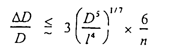 D = le diamètre du tube devant être relié ;l = la longueur moyenne de la section de tube devant être relié ; etn = le nombre de connecteurs présents dans une canalisation tubulaire.
 - Canalisation tubulaire selon la revendication 4, caractérisée en ce que l'équation suivante vaut pour la dimension de l'espace ΔD :
- Canalisation tubulaire selon l'une quelconque des revendications 1 à 5, caractérisée en ce que les ouvertures des connecteurs de tubes destinées à recevoir les extrémités des tubes (2, 3) sont munies de saillies (4) en forme de barbes au niveau de l'intérieur.
- Canalisation tubulaire selon au moins une des revendications 1 à 5, caractérisée en ce que, sur la paroi intérieure du corps creux des connecteurs de tubes, approximativement au milieu de ces derniers, est fournie une arête annulaire (5) qui forme un butoir pour les extrémités respectives des tubes (2, 3) devant être reliés.
- Canalisation tubulaire selon l'une quelconque des revendications 1 à 3, caractérisée en ce qu'une ouverture de passage d'air (6) est ménagée dans une arête annulaire (5) formée sur la paroi intérieure du corps creux du connecteur de tube, approximativement au milieu de ce dernier, laquelle arête forme un butoir pour les extrémités respectives des tubes (2, 3) devant être reliés.
Applications Claiming Priority (3)
| Application Number | Priority Date | Filing Date | Title |
|---|---|---|---|
| NL1003249A NL1003249C2 (nl) | 1996-05-31 | 1996-05-31 | Buisconnector voor het verbinden van voor het daarin installeren van kabels bestemde buizen. |
| NL1003249 | 1996-05-31 | ||
| PCT/NL1997/000309 WO1997045668A1 (fr) | 1996-05-31 | 1997-06-02 | Connecteur pour le raccordement de tubes destines a l'installation de cables |
Publications (2)
| Publication Number | Publication Date |
|---|---|
| EP0901593A1 EP0901593A1 (fr) | 1999-03-17 |
| EP0901593B1 true EP0901593B1 (fr) | 2001-02-21 |
Family
ID=19762951
Family Applications (1)
| Application Number | Title | Priority Date | Filing Date |
|---|---|---|---|
| EP97924383A Expired - Lifetime EP0901593B1 (fr) | 1996-05-31 | 1997-06-02 | Connecteur pour le raccordement de tubes destines a l'installation de cables |
Country Status (10)
| Country | Link |
|---|---|
| US (1) | US6024387A (fr) |
| EP (1) | EP0901593B1 (fr) |
| AT (1) | ATE199277T1 (fr) |
| DE (1) | DE69704116T2 (fr) |
| DK (1) | DK0901593T3 (fr) |
| ES (1) | ES2156384T3 (fr) |
| GR (1) | GR3035894T3 (fr) |
| NL (1) | NL1003249C2 (fr) |
| PT (1) | PT901593E (fr) |
| WO (1) | WO1997045668A1 (fr) |
Families Citing this family (4)
| Publication number | Priority date | Publication date | Assignee | Title |
|---|---|---|---|---|
| US6354331B1 (en) | 1999-11-08 | 2002-03-12 | Parker-Hannifin Corp. | Flexible plastic tubing construction having a sight glass window |
| US7992685B2 (en) * | 2002-07-11 | 2011-08-09 | Draka Comteq B.V. | Optical cable lubricator with reservoir |
| US6848541B2 (en) * | 2002-07-11 | 2005-02-01 | Nkf Kabel B.V. | Optical cable installation with cable lubricator |
| JP5426557B2 (ja) * | 2007-10-03 | 2014-02-26 | サン−ゴバン グラス フランス | 2つの中空セクション部品端接続用コネクタ |
Family Cites Families (31)
| Publication number | Priority date | Publication date | Assignee | Title |
|---|---|---|---|---|
| US2649105A (en) * | 1953-08-18 | Self-draining pipe joint | ||
| DE205301C (fr) * | ||||
| GB189519854A (en) * | 1895-10-22 | 1895-11-23 | James Wills | Improvements in Pipe Joints or Couplings. |
| US1145679A (en) * | 1911-03-02 | 1915-07-06 | Harry P Wallace | Waste and revent fitting. |
| US1059560A (en) * | 1911-11-15 | 1913-04-22 | Clarence L Parker | Pump-rod coupling. |
| US1671979A (en) * | 1925-11-27 | 1928-06-05 | William E Cook | Wire splice |
| GB318751A (en) * | 1928-09-17 | 1929-09-12 | Reginald Harvey Hellyer | Improvements in or relating to pipe joints |
| US1822056A (en) * | 1929-02-07 | 1931-09-08 | Gillette Vibber Company Inc | Threadless pipe connecter |
| US1970673A (en) * | 1930-04-08 | 1934-08-21 | Detachable Bit Corp Of America | Drill |
| US2158757A (en) * | 1938-07-11 | 1939-05-16 | William J Katzberg | Coupling |
| US2523716A (en) * | 1946-11-18 | 1950-09-26 | Edward L Parr | Hydraulic coupling |
| US2530700A (en) * | 1947-11-03 | 1950-11-21 | Joints Inc | Pressure pipe joint |
| US2679414A (en) * | 1949-02-01 | 1954-05-25 | Ingersoll Rand Co | Separator for shafts |
| DE1750710B1 (de) * | 1968-05-28 | 1971-09-23 | Fouquet Werk Frauz & Planck | Rohrkupplung |
| US3995897A (en) * | 1975-04-21 | 1976-12-07 | Eaton Corporation | Coupling |
| US4073514A (en) * | 1976-05-26 | 1978-02-14 | Indian Head Inc. | Combination pipe fitting and retainer ring |
| US4346923A (en) * | 1979-08-23 | 1982-08-31 | Vaponics Inc. | Apparatus for joining tubing |
| EP0108590B1 (fr) * | 1982-11-08 | 1986-11-26 | BRITISH TELECOMMUNICATIONS public limited company | Fibres optiques de transmission |
| GB8408156D0 (en) * | 1984-03-29 | 1984-05-10 | Bicc Plc | Manufacture of optical cable |
| US4640576A (en) * | 1984-06-26 | 1987-02-03 | Canada Wire And Cable Limited | Method and apparatus for tubing optical fibers |
| FR2573165B1 (fr) * | 1984-10-19 | 1988-05-20 | Levenez Yves | Raccords commutateurs rotatifs. |
| GB8706803D0 (en) * | 1987-03-23 | 1987-04-29 | British Telecomm | Optical fibre installation |
| NL193126B (nl) * | 1987-04-28 | 1998-07-01 | Nederland Ptt | Werkwijze en inrichting voor het aanbrengen van een kabel in een kabelgeleidingsbuis. |
| US5065928A (en) * | 1987-11-25 | 1991-11-19 | Bicc Plc. | Method and apparatus for blowing an optical fibre member |
| DE3844421A1 (de) * | 1988-03-17 | 1989-09-28 | Max Pasbrig | Loesbare verbindungsvorrichtung fuer rohre, schlaeuche, stangen o.dgl. |
| GB8815741D0 (en) * | 1988-07-01 | 1988-08-10 | Bicc Plc | Connecting device |
| FR2672371B1 (fr) * | 1991-02-04 | 1993-07-16 | Pont A Mousson | Manchon composite, procede pour sa mise en óoeuvre, et joint d'etancheite en comportant application. |
| CH682691A5 (de) * | 1991-04-16 | 1993-10-29 | Christoph Morach | Rohrmuffe für Kabelrohre. |
| FR2710789B1 (fr) * | 1993-09-27 | 1995-12-22 | Alain Pecot | Vanne pour la régénération du débit d'air d'entraînement d'un câble de télécommunications dans une conduite enterrée. |
| US5588685A (en) * | 1995-07-06 | 1996-12-31 | Ameron International Corporation | Push-pull pipe joint |
| US5647681A (en) * | 1996-06-18 | 1997-07-15 | Chen; Chi-Fu | Stairs rail connector |
-
1996
- 1996-05-31 NL NL1003249A patent/NL1003249C2/nl not_active IP Right Cessation
-
1997
- 1997-06-02 PT PT97924383T patent/PT901593E/pt unknown
- 1997-06-02 AT AT97924383T patent/ATE199277T1/de not_active IP Right Cessation
- 1997-06-02 DE DE69704116T patent/DE69704116T2/de not_active Expired - Lifetime
- 1997-06-02 US US08/867,074 patent/US6024387A/en not_active Expired - Fee Related
- 1997-06-02 WO PCT/NL1997/000309 patent/WO1997045668A1/fr not_active Ceased
- 1997-06-02 EP EP97924383A patent/EP0901593B1/fr not_active Expired - Lifetime
- 1997-06-02 ES ES97924383T patent/ES2156384T3/es not_active Expired - Lifetime
- 1997-06-02 DK DK97924383T patent/DK0901593T3/da active
-
2001
- 2001-05-18 GR GR20010400747T patent/GR3035894T3/el not_active IP Right Cessation
Also Published As
| Publication number | Publication date |
|---|---|
| DE69704116D1 (de) | 2001-03-29 |
| DK0901593T3 (da) | 2001-06-05 |
| PT901593E (pt) | 2001-05-31 |
| GR3035894T3 (en) | 2001-08-31 |
| ATE199277T1 (de) | 2001-03-15 |
| WO1997045668A1 (fr) | 1997-12-04 |
| NL1003249C2 (nl) | 1997-12-03 |
| EP0901593A1 (fr) | 1999-03-17 |
| US6024387A (en) | 2000-02-15 |
| DE69704116T2 (de) | 2001-09-27 |
| ES2156384T3 (es) | 2001-06-16 |
Similar Documents
| Publication | Publication Date | Title |
|---|---|---|
| US6170804B1 (en) | Method and apparatus for introducing a cable into a conduit | |
| US5078432A (en) | Multiple duct conduit and couplings | |
| EP0780942B1 (fr) | Procédé d'installation d'un embranchement de tube pour un câble de télécommunication et élément d'embranchement utilisant pour un tel procédé | |
| US20020079697A1 (en) | Y-branch splittable connector | |
| CN101377558B (zh) | 改进型预箍金属式通信线缆组件和安装方法 | |
| US5503369A (en) | Optical fibre customer lead in | |
| US20060133758A1 (en) | Optical fiber termination apparatus with connector adaptor and method for using the same | |
| EP0278544B1 (fr) | Dispositif d'étanchéite | |
| JPH02503040A (ja) | 伝送線の布設方法および装置 | |
| GB2229549A (en) | Hydraulic cable installation system | |
| US6409155B1 (en) | Method of inserting a light transmitting member into a tube | |
| US6024387A (en) | Tube connector for connecting tubes intended for installing cables therein | |
| FI100493B (fi) | Menetelmä ja vetotulppa, joita käytetään kaapelin asentamiseksi kaapel iputkeen | |
| US7344314B2 (en) | Joining optical fibres | |
| EP0691557B1 (fr) | Joint de gaz | |
| DE19734274B4 (de) | Kommunikationsnetz mit Lichtwellenleitern zwischen Teilnehmern und Kommunikationzentralen in bestehenden Versorgungsleitungen | |
| US4600176A (en) | Apparatus for producing a cable conduit system suitable for the drawing-in of cables | |
| AU643554B2 (en) | Device for passing wire | |
| NL1003130C2 (nl) | Trekorgaan voor het installeren van een kabel in een buis alsmede een buizenstelsel voorzien van een dergelijk trekorgaan. | |
| CN117836687A (zh) | 端接光纤光缆的装置和方法 | |
| AU9560598A (en) | Method for installing cables in tubes and apparatus for practicing this method | |
| Griffioen et al. | A new fiber optic life for old ducts | |
| JPS61267710A (ja) | フアイバ−光デ−タ−ネツトワ−ク | |
| JP3317021B2 (ja) | 光ファイバの布設装置 | |
| WO2003060585A1 (fr) | Procede de pose d'un cable a fibres optiques dans une canalisation de gaz et dispositif de pose de cables correspondant |
Legal Events
| Date | Code | Title | Description |
|---|---|---|---|
| PUAI | Public reference made under article 153(3) epc to a published international application that has entered the european phase |
Free format text: ORIGINAL CODE: 0009012 |
|
| 17P | Request for examination filed |
Effective date: 19981103 |
|
| AK | Designated contracting states |
Kind code of ref document: A1 Designated state(s): AT BE CH DE DK ES FI FR GB GR IE IT LI LU NL PT SE |
|
| GRAG | Despatch of communication of intention to grant |
Free format text: ORIGINAL CODE: EPIDOS AGRA |
|
| 17Q | First examination report despatched |
Effective date: 20000502 |
|
| GRAG | Despatch of communication of intention to grant |
Free format text: ORIGINAL CODE: EPIDOS AGRA |
|
| GRAH | Despatch of communication of intention to grant a patent |
Free format text: ORIGINAL CODE: EPIDOS IGRA |
|
| GRAH | Despatch of communication of intention to grant a patent |
Free format text: ORIGINAL CODE: EPIDOS IGRA |
|
| GRAA | (expected) grant |
Free format text: ORIGINAL CODE: 0009210 |
|
| AK | Designated contracting states |
Kind code of ref document: B1 Designated state(s): AT BE CH DE DK ES FI FR GB GR IE IT LI LU NL PT SE |
|
| REF | Corresponds to: |
Ref document number: 199277 Country of ref document: AT Date of ref document: 20010315 Kind code of ref document: T |
|
| REG | Reference to a national code |
Ref country code: CH Ref legal event code: EP |
|
| REG | Reference to a national code |
Ref country code: CH Ref legal event code: NV Representative=s name: TROESCH SCHEIDEGGER WERNER AG |
|
| REG | Reference to a national code |
Ref country code: IE Ref legal event code: FG4D |
|
| REF | Corresponds to: |
Ref document number: 69704116 Country of ref document: DE Date of ref document: 20010329 |
|
| ET | Fr: translation filed | ||
| ITF | It: translation for a ep patent filed | ||
| REG | Reference to a national code |
Ref country code: PT Ref legal event code: SC4A Free format text: AVAILABILITY OF NATIONAL TRANSLATION Effective date: 20010308 |
|
| REG | Reference to a national code |
Ref country code: DK Ref legal event code: T3 |
|
| REG | Reference to a national code |
Ref country code: ES Ref legal event code: FG2A Ref document number: 2156384 Country of ref document: ES Kind code of ref document: T3 |
|
| PLBE | No opposition filed within time limit |
Free format text: ORIGINAL CODE: 0009261 |
|
| STAA | Information on the status of an ep patent application or granted ep patent |
Free format text: STATUS: NO OPPOSITION FILED WITHIN TIME LIMIT |
|
| REG | Reference to a national code |
Ref country code: GB Ref legal event code: IF02 |
|
| 26N | No opposition filed | ||
| PGFP | Annual fee paid to national office [announced via postgrant information from national office to epo] |
Ref country code: LU Payment date: 20080613 Year of fee payment: 12 Ref country code: DK Payment date: 20080610 Year of fee payment: 12 |
|
| PGFP | Annual fee paid to national office [announced via postgrant information from national office to epo] |
Ref country code: AT Payment date: 20080616 Year of fee payment: 12 |
|
| PGFP | Annual fee paid to national office [announced via postgrant information from national office to epo] |
Ref country code: FI Payment date: 20080613 Year of fee payment: 12 Ref country code: PT Payment date: 20080530 Year of fee payment: 12 |
|
| PGFP | Annual fee paid to national office [announced via postgrant information from national office to epo] |
Ref country code: SE Payment date: 20080612 Year of fee payment: 12 |
|
| PGFP | Annual fee paid to national office [announced via postgrant information from national office to epo] |
Ref country code: BE Payment date: 20080728 Year of fee payment: 12 |
|
| PGFP | Annual fee paid to national office [announced via postgrant information from national office to epo] |
Ref country code: GR Payment date: 20080620 Year of fee payment: 12 |
|
| REG | Reference to a national code |
Ref country code: PT Ref legal event code: MM4A Free format text: LAPSE DUE TO NON-PAYMENT OF FEES Effective date: 20091202 |
|
| BERE | Be: lapsed |
Owner name: KONINKLIJKE *KPN N.V. Effective date: 20090630 |
|
| PG25 | Lapsed in a contracting state [announced via postgrant information from national office to epo] |
Ref country code: FI Free format text: LAPSE BECAUSE OF NON-PAYMENT OF DUE FEES Effective date: 20090602 |
|
| REG | Reference to a national code |
Ref country code: DK Ref legal event code: EBP |
|
| PG25 | Lapsed in a contracting state [announced via postgrant information from national office to epo] |
Ref country code: PT Free format text: LAPSE BECAUSE OF NON-PAYMENT OF DUE FEES Effective date: 20091202 |
|
| PG25 | Lapsed in a contracting state [announced via postgrant information from national office to epo] |
Ref country code: BE Free format text: LAPSE BECAUSE OF NON-PAYMENT OF DUE FEES Effective date: 20090630 Ref country code: AT Free format text: LAPSE BECAUSE OF NON-PAYMENT OF DUE FEES Effective date: 20090602 |
|
| PG25 | Lapsed in a contracting state [announced via postgrant information from national office to epo] |
Ref country code: DK Free format text: LAPSE BECAUSE OF NON-PAYMENT OF DUE FEES Effective date: 20090630 |
|
| PGFP | Annual fee paid to national office [announced via postgrant information from national office to epo] |
Ref country code: IE Payment date: 20100618 Year of fee payment: 14 Ref country code: FR Payment date: 20100706 Year of fee payment: 14 Ref country code: ES Payment date: 20100625 Year of fee payment: 14 |
|
| PGFP | Annual fee paid to national office [announced via postgrant information from national office to epo] |
Ref country code: IT Payment date: 20100625 Year of fee payment: 14 |
|
| PG25 | Lapsed in a contracting state [announced via postgrant information from national office to epo] |
Ref country code: GR Free format text: LAPSE BECAUSE OF NON-PAYMENT OF DUE FEES Effective date: 20100107 |
|
| PGFP | Annual fee paid to national office [announced via postgrant information from national office to epo] |
Ref country code: NL Payment date: 20100614 Year of fee payment: 14 Ref country code: CH Payment date: 20100623 Year of fee payment: 14 |
|
| PGFP | Annual fee paid to national office [announced via postgrant information from national office to epo] |
Ref country code: GB Payment date: 20100618 Year of fee payment: 14 Ref country code: DE Payment date: 20100625 Year of fee payment: 14 |
|
| PG25 | Lapsed in a contracting state [announced via postgrant information from national office to epo] |
Ref country code: LU Free format text: LAPSE BECAUSE OF NON-PAYMENT OF DUE FEES Effective date: 20090602 |
|
| PG25 | Lapsed in a contracting state [announced via postgrant information from national office to epo] |
Ref country code: SE Free format text: LAPSE BECAUSE OF NON-PAYMENT OF DUE FEES Effective date: 20090603 |
|
| REG | Reference to a national code |
Ref country code: NL Ref legal event code: V1 Effective date: 20120101 |
|
| REG | Reference to a national code |
Ref country code: CH Ref legal event code: PL |
|
| GBPC | Gb: european patent ceased through non-payment of renewal fee |
Effective date: 20110602 |
|
| PG25 | Lapsed in a contracting state [announced via postgrant information from national office to epo] |
Ref country code: IT Free format text: LAPSE BECAUSE OF NON-PAYMENT OF DUE FEES Effective date: 20110602 |
|
| REG | Reference to a national code |
Ref country code: FR Ref legal event code: ST Effective date: 20120229 |
|
| REG | Reference to a national code |
Ref country code: IE Ref legal event code: MM4A |
|
| REG | Reference to a national code |
Ref country code: DE Ref legal event code: R119 Ref document number: 69704116 Country of ref document: DE Effective date: 20120103 |
|
| PG25 | Lapsed in a contracting state [announced via postgrant information from national office to epo] |
Ref country code: LI Free format text: LAPSE BECAUSE OF NON-PAYMENT OF DUE FEES Effective date: 20110630 Ref country code: CH Free format text: LAPSE BECAUSE OF NON-PAYMENT OF DUE FEES Effective date: 20110630 Ref country code: IE Free format text: LAPSE BECAUSE OF NON-PAYMENT OF DUE FEES Effective date: 20110602 Ref country code: FR Free format text: LAPSE BECAUSE OF NON-PAYMENT OF DUE FEES Effective date: 20110630 Ref country code: DE Free format text: LAPSE BECAUSE OF NON-PAYMENT OF DUE FEES Effective date: 20120103 |
|
| PG25 | Lapsed in a contracting state [announced via postgrant information from national office to epo] |
Ref country code: NL Free format text: LAPSE BECAUSE OF NON-PAYMENT OF DUE FEES Effective date: 20120101 |
|
| PG25 | Lapsed in a contracting state [announced via postgrant information from national office to epo] |
Ref country code: GB Free format text: LAPSE BECAUSE OF NON-PAYMENT OF DUE FEES Effective date: 20110602 |
|
| REG | Reference to a national code |
Ref country code: ES Ref legal event code: FD2A Effective date: 20130405 |
|
| PG25 | Lapsed in a contracting state [announced via postgrant information from national office to epo] |
Ref country code: ES Free format text: LAPSE BECAUSE OF NON-PAYMENT OF DUE FEES Effective date: 20110603 |