EP0901611B1 - Detecteur optique pour la determination de l'angle de rotation d'un axe de rotation - Google Patents
Detecteur optique pour la determination de l'angle de rotation d'un axe de rotation Download PDFInfo
- Publication number
- EP0901611B1 EP0901611B1 EP97923995A EP97923995A EP0901611B1 EP 0901611 B1 EP0901611 B1 EP 0901611B1 EP 97923995 A EP97923995 A EP 97923995A EP 97923995 A EP97923995 A EP 97923995A EP 0901611 B1 EP0901611 B1 EP 0901611B1
- Authority
- EP
- European Patent Office
- Prior art keywords
- optical
- radiation
- optical elements
- structures
- optical sensor
- Prior art date
- Legal status (The legal status is an assumption and is not a legal conclusion. Google has not performed a legal analysis and makes no representation as to the accuracy of the status listed.)
- Expired - Lifetime
Links
- 230000003287 optical effect Effects 0.000 title claims description 137
- 230000005855 radiation Effects 0.000 claims description 64
- 230000003993 interaction Effects 0.000 claims description 4
- 238000005259 measurement Methods 0.000 claims description 4
- 230000005693 optoelectronics Effects 0.000 claims description 4
- 238000005530 etching Methods 0.000 claims description 3
- 238000003825 pressing Methods 0.000 claims description 3
- 230000010076 replication Effects 0.000 claims description 3
- 239000004020 conductor Substances 0.000 claims description 2
- 230000001419 dependent effect Effects 0.000 claims description 2
- 238000004049 embossing Methods 0.000 claims description 2
- 238000001746 injection moulding Methods 0.000 claims description 2
- 238000001459 lithography Methods 0.000 claims description 2
- 230000008021 deposition Effects 0.000 claims 1
- 238000003801 milling Methods 0.000 claims 1
- 238000003384 imaging method Methods 0.000 description 14
- 239000000463 material Substances 0.000 description 12
- 238000004519 manufacturing process Methods 0.000 description 9
- 230000010354 integration Effects 0.000 description 7
- 239000000758 substrate Substances 0.000 description 4
- 238000013461 design Methods 0.000 description 3
- 239000011521 glass Substances 0.000 description 3
- 238000000034 method Methods 0.000 description 3
- 239000000126 substance Substances 0.000 description 3
- 230000008901 benefit Effects 0.000 description 2
- 230000005540 biological transmission Effects 0.000 description 2
- 230000008859 change Effects 0.000 description 2
- 238000011161 development Methods 0.000 description 2
- 230000018109 developmental process Effects 0.000 description 2
- 230000007774 longterm Effects 0.000 description 2
- 230000007246 mechanism Effects 0.000 description 2
- 238000012634 optical imaging Methods 0.000 description 2
- 230000008569 process Effects 0.000 description 2
- 238000012545 processing Methods 0.000 description 2
- 239000000243 solution Substances 0.000 description 2
- 238000012935 Averaging Methods 0.000 description 1
- VYPSYNLAJGMNEJ-UHFFFAOYSA-N Silicium dioxide Chemical compound O=[Si]=O VYPSYNLAJGMNEJ-UHFFFAOYSA-N 0.000 description 1
- 238000010276 construction Methods 0.000 description 1
- 238000006073 displacement reaction Methods 0.000 description 1
- 238000009826 distribution Methods 0.000 description 1
- 230000000694 effects Effects 0.000 description 1
- 238000005516 engineering process Methods 0.000 description 1
- 238000011156 evaluation Methods 0.000 description 1
- 230000008020 evaporation Effects 0.000 description 1
- 238000001704 evaporation Methods 0.000 description 1
- 239000004922 lacquer Substances 0.000 description 1
- 239000007788 liquid Substances 0.000 description 1
- 238000000206 photolithography Methods 0.000 description 1
- 238000001020 plasma etching Methods 0.000 description 1
- 230000003362 replicative effect Effects 0.000 description 1
- 230000035945 sensitivity Effects 0.000 description 1
- 239000007787 solid Substances 0.000 description 1
- 238000005507 spraying Methods 0.000 description 1
- 230000007704 transition Effects 0.000 description 1
- 238000005019 vapor deposition process Methods 0.000 description 1
- 239000002966 varnish Substances 0.000 description 1
Images


Classifications
-
- G—PHYSICS
- G01—MEASURING; TESTING
- G01D—MEASURING NOT SPECIALLY ADAPTED FOR A SPECIFIC VARIABLE; ARRANGEMENTS FOR MEASURING TWO OR MORE VARIABLES NOT COVERED IN A SINGLE OTHER SUBCLASS; TARIFF METERING APPARATUS; MEASURING OR TESTING NOT OTHERWISE PROVIDED FOR
- G01D5/00—Mechanical means for transferring the output of a sensing member; Means for converting the output of a sensing member to another variable where the form or nature of the sensing member does not constrain the means for converting; Transducers not specially adapted for a specific variable
- G01D5/26—Mechanical means for transferring the output of a sensing member; Means for converting the output of a sensing member to another variable where the form or nature of the sensing member does not constrain the means for converting; Transducers not specially adapted for a specific variable characterised by optical transfer means, i.e. using infrared, visible, or ultraviolet light
- G01D5/32—Mechanical means for transferring the output of a sensing member; Means for converting the output of a sensing member to another variable where the form or nature of the sensing member does not constrain the means for converting; Transducers not specially adapted for a specific variable characterised by optical transfer means, i.e. using infrared, visible, or ultraviolet light with attenuation or whole or partial obturation of beams of light
- G01D5/34—Mechanical means for transferring the output of a sensing member; Means for converting the output of a sensing member to another variable where the form or nature of the sensing member does not constrain the means for converting; Transducers not specially adapted for a specific variable characterised by optical transfer means, i.e. using infrared, visible, or ultraviolet light with attenuation or whole or partial obturation of beams of light the beams of light being detected by photocells
- G01D5/36—Forming the light into pulses
- G01D5/38—Forming the light into pulses by diffraction gratings
-
- G—PHYSICS
- G01—MEASURING; TESTING
- G01D—MEASURING NOT SPECIALLY ADAPTED FOR A SPECIFIC VARIABLE; ARRANGEMENTS FOR MEASURING TWO OR MORE VARIABLES NOT COVERED IN A SINGLE OTHER SUBCLASS; TARIFF METERING APPARATUS; MEASURING OR TESTING NOT OTHERWISE PROVIDED FOR
- G01D5/00—Mechanical means for transferring the output of a sensing member; Means for converting the output of a sensing member to another variable where the form or nature of the sensing member does not constrain the means for converting; Transducers not specially adapted for a specific variable
- G01D5/26—Mechanical means for transferring the output of a sensing member; Means for converting the output of a sensing member to another variable where the form or nature of the sensing member does not constrain the means for converting; Transducers not specially adapted for a specific variable characterised by optical transfer means, i.e. using infrared, visible, or ultraviolet light
- G01D5/32—Mechanical means for transferring the output of a sensing member; Means for converting the output of a sensing member to another variable where the form or nature of the sensing member does not constrain the means for converting; Transducers not specially adapted for a specific variable characterised by optical transfer means, i.e. using infrared, visible, or ultraviolet light with attenuation or whole or partial obturation of beams of light
- G01D5/34—Mechanical means for transferring the output of a sensing member; Means for converting the output of a sensing member to another variable where the form or nature of the sensing member does not constrain the means for converting; Transducers not specially adapted for a specific variable characterised by optical transfer means, i.e. using infrared, visible, or ultraviolet light with attenuation or whole or partial obturation of beams of light the beams of light being detected by photocells
- G01D5/347—Mechanical means for transferring the output of a sensing member; Means for converting the output of a sensing member to another variable where the form or nature of the sensing member does not constrain the means for converting; Transducers not specially adapted for a specific variable characterised by optical transfer means, i.e. using infrared, visible, or ultraviolet light with attenuation or whole or partial obturation of beams of light the beams of light being detected by photocells using displacement encoding scales
- G01D5/34707—Scales; Discs, e.g. fixation, fabrication, compensation
- G01D5/34715—Scale reading or illumination devices
Definitions
- an optical position measuring device is specified with which relative displacements of a moving object can be measured can.
- the light beam from a light source is transmitted from one to the other First diffraction grating located in transparent substrate in several Beams of light split, which in turn are diffracted at one on the Object attached diffraction grating scale to a second diffraction grating hit on the substrate.
- the rays of light overlap differently there Diffraction orders, the interference phase of two photosensors is measured.
- a rotation angle transmitter in which one rotating scale is designed as a diffraction grating. A falling on it Light beam is diffracted, with two diffracted light beams being more predetermined Order by means of optical elements to a second position on the diffraction grating be guided and bent there again. The light rays of two Diffraction orders are brought to interference. The emerging Interference signals are detected by a photosensor, from which the Rotation of the scale with respect to the photosensor is determined.
- Optical sensors for determining the angle of rotation are among others in geodetic devices used for angle measurement. So be for example, in a theodolite, the angle of rotation of the swivel axes of the Theodolite telescope measured to thereby the elevation angle and the Determine the side angle (azimuth) to a targeted target point.
- Such Rotation angle measurements are known from EP 00 85 951 B1.
- the optics consist of individual ones optical components that have mechanical sockets and mounts to each other, to the light source and to the photoreceiver arrangement mechanically must be adjustable.
- EP 0 417 742 B1 is used for a rotation angle measuring device or for use in rotary encoders described an electro-optical scanning unit in which light is a Condenser lens and a scanning plate with a translucent division crosses. The light is made movable by a scanner plate translucent scale modulated and then by at least one photoelectric receiver element detected. Each is there Receiver element individually adjustable with the help of a fine adjustment to a to be able to set the optimal position with respect to the optical axis. A such mechanical variable adjustment of the receiver elements means a considerable design effort.
- the rotation angle measuring devices mentioned need for optical radiation guidance individual optical and mechanical components, that are manufactured, assembled, assembled and precisely adjusted to each other have to. Most of the components remain displaceable and adjustable. As a result, the optical-mechanical structure is complex. The effort will still be elevated. if high optical-mechanical or thermal stability is required.
- the object is achieved in that the optical elements monolithic on or / and in a base body made of optically conductive material are integrated, whereby the radiation is guided within the base body, and in the area of each or each of the first and second optical Elements the radiation is reflected exactly once or only one Diffraction order of the radiation is continued and that the base body Has surface areas from which, in use, the radiation after the first optical elements emerges in the direction of the disc and into which the radiation after their interaction with the structures of the Disc enters the base body again.
- P. 1594-1596 becomes an integrated planar optical Imaging system that describes the structure of a pixel array of an input side to an output side of a hybrid Imaging system is transmitted via a closed beam path.
- the radiation guidance is designed so that the radiation in a certain area of the base body leaves this to with the structures of a disc interact with the angle of rotation. The radiation then re-enters the body. Everyone is there Changes in position of the radiation on the detector exclusively on the Interaction with the structures of the disc outside the base body due.
- the radiation guidance in the base body through the monolithic integrated optical elements remains stable.
- the monolithic integration also opens up a wide variety of design options for the optical elements and easy customization when in use different panes with different structures.
- optical elements on or / and in a basic body both in the narrower and in one other senses can be understood.
- Strictly monolithically integrated means that all optical elements emerge from the same basic body - directly during the manufacture of the base body or during its processing. So for example, optical elements can be etched out of the base body, milled out or etched in the base body, milled or appropriate structures can be engraved, pressed or stamped. As well they can also be created by blank pressing or by injection molding.
- optical elements apply.
- This deformable materials on the Base body applied and by means of an impression form in a certain brought geometric shape and then e.g. through chemical, thermal or UV treatment in its geometry and fixed on the base body.
- the optical elements are already insoluble with one another when they are generated aligned.
- optical elements that are formed by evaporation of Materials created on the base body are integrated as monolithic be understood.
- An optical element can be monolithic on its own on a base body to get integrated.
- the great advantages of monolithic arise Integration through the simultaneous production of a large number of similar or different optical elements on a common Body. So all necessary for the rotation angle sensor imaging and radiation-deflecting optical elements as complete Unity in a manufacturing process arise simultaneously. It did found that the manufacturing reliability of such a unit is very high is.
- Reflective, refractive or diffractive optical ones can be used for the radiation guidance Elements are used.
- Non-imaging optical elements for Radiation guidance within the base body are advantageous Surfaces of the basic body itself, on which a total reflection Radiation deflection can take place.
- a radiation deflection can also can be achieved by reflective films that are in certain places on the Base body surface are applied.
- the reflective optical elements can also be spherical or have aspherical surfaces. As a result, they also receive imaging properties. Thus, the entire look of the Represent rotation angle sensor alone with various reflective elements and as a single monolithic unit.
- Such a unit can, for example, be made of glass by blank pressing or Plastic can be produced by spraying technology.
- the so made monolithic unit can or can be mounted on a carrier plate take on the role of the carrier plate.
- the individual units can be a certain distance apart own or be built directly on top of each other. This gives you one greater scope for the optical path lengths or for the arrangement of the integrated optical elements with each other.
- Integrated refractive optical elements are both radiation-deflecting as well as to achieve imaging properties. For this purpose, are known in Way prism and lens effects exploited. Of course there is Combination of refractive and reflective optical elements on one Basic body possible. Due to the monolithic integration, for such a rotation angle sensor cost and space savings.
- Fresnel lenses and mirrors are optical elements whose surfaces only are gradually continuous.
- radiation-deflecting are also and imaging optical elements, such as with a Fresnel - Zone plate or with a holographic element, i.e. an element with locally variable lattice structure.
- microgrid structures are in the surface in different ways of a basic body can be implemented.
- the structures there can be produced by etching or embossing.
- Various lithography, etching and vapor deposition processes are known. In particular structures with optical lithography and reactive ion etching Glass substrates manufactured.
- Another group of processes for manufacturing integrated optical Elements are holographic processes that involve interference multiple areas of light distribution create areas with spatially varying intensity to let. Bring in a glass plate coated with light-sensitive varnish the interference area, there is a correspondingly spatially variable Exposure, which after the development of the lacquer as a diffractive grating structure in the sense of the statements made above works.
- the Radiation source and first radiation deflecting and imaging monolithically integrated optical elements partially the structured pane or fully illuminated.
- the radiation leaves the body in a designated surface area.
- the illuminated structures design an intensity pattern on the detector.
- the location sensitive optoelectronic detector sets the intensity pattern in corresponding electrical signals for further evaluation. Because depending on the angle of rotation Disc a changed intensity pattern appears on the detector the angle of rotation position of the disk can be determined therefrom. Thus the Azimuth angle of the axis of rotation of the disk determined.
- the intensity patterns can vary due to different types of structures be generated. This can vary depending on the location reflective structures can be applied.
- the radiation reflected on it forms a corresponding intensity pattern on the detector.
- the pane can be provided with transmissive structures depending on the location be used in transmitted light. For example, a Turn part of the disc through a gap in the base body and the Radiation emerges from the body above the disc and the Radiation entry into the base body is located below the pane. The location-dependent transmission of the disk also leads to corresponding Intensity patterns on the detector.
- Such transmissive structures will as well as the above-mentioned reflective structures projected onto the detector or pictured.
- structures with others can also be on the disc optical mechanisms are implemented. So by refraction or Diffraction the wave fronts of the radiation are spatially influenced. By differently refractive structures on the disc will emit radiation directed different directions. Due to diffraction structures Diffraction maxima of different orders. Thus, even with refractive or diffractive structures two-dimensional intensity patterns on the Detector are generated.
- the structures on the pane are advantageously integrated monolithically.
- the structures can be an annular surface or the entire surface of the Cover disk and they can even be designed so that they in addition to the generation of intensity patterns, also imaging Have properties.
- the measured intensity pattern is evaluated, for example, with the known method of averaging or by fit algorithms.
- a special measuring sensitivity results from an intensity pattern, its local fundamental frequency or one of its harmonic local upper frequencies with the spatial fundamental frequency of the radiation-sensitive structures of the detector forms a low frequency overlay pattern.
- the low frequency Overlay patterns work in the same way as a moiré pattern.
- Moire patterns are known to be very sensitive to a shift in the they generate structures react. This means that already at one compared to very little change in the intensity pattern on the detector whose pixel structure is the low-frequency overlay pattern in his Spatial frequency changes significantly. The change in the overlay pattern is therefore a very sensitive indicator for changes in the angle of rotation of the Disc, which can be measured very precisely.
- An optical rotation angle sensor 50 according to the invention is shown schematically in FIG shown in cross section. It is equipped with reflective optical elements 2a, 2b, 3a, 3b equipped, their reflection properties for the radiation guidance be exploited.
- the optical elements 2a, 2b, 3a, 3b are according to the Definition integrated at the beginning of the description in the strict sense monolithically, i.e. they consist of one and the same basic body 1 and are part of it Manufactured or machined from a single piece.
- the reflective optical elements 2a, 2b, 3a, 3b are in this embodiment with curved surfaces, which is why they are imaging Possess properties.
- a radiation source 6 and the first
- the structures 11 of a pane 10 become optical elements 2a and 3a partially illuminated.
- the radiation leaves the body in the direction of Disc 10.
- the disc 10 is rotatable with the axis of rotation 12, which are relative to each other of the base body 1 is in a fixed spatial position.
- the axis of rotation 12 can e.g. each the pivot axes of a theodolite or tachymeter Display height and side angle measurement.
- the structures 11 of the disc 10 are assigned to the angle of rotation ⁇ of the axis of rotation 12.
- the radiation occurs back into the base body 1 and is by the second optical elements 3b and 2b focused on a location-sensitive optoelectronic detector 7.
- An intensity pattern 21 is generated on the detector 7 by the structures 11.
- the associated detector signals are not shown here Processing electronics processed.
- the flat surface 9 of the base body 1 is used for radiation reflection, in order to overall to ensure a continuous beam path.
- the surface 9 can be coated with reflective materials or to be steamed. This option is also available for the reflective surfaces optical elements 2a, 2b, 3a, 3b. But also total reflection can be exploited.
- FIG. 1 shows all elements of the angle of rotation sensor 50 like that Radiation source 6, the disc 10, the detector 7 and the optical elements 2a, 2b, 3a, 3b arranged linearly one behind the other. This is for the overall function of the angle of rotation sensor 50 but not absolutely necessary.
- the above Elements can also be laterally offset from one another on or in the base body 1 be integrated monolithically, the radiation guide accordingly is interpreted.
- the structures 11 of the pane 10 can be reflective for the incident radiation, be refractive or diffractive. It is also possible to use transmissive structures 11 be used if the base body has an appropriate shape for the Operation of the disc 10 in transmission, as already described above. Since the structures 11 are different depending on the angle of rotation ⁇ Generate intensity pattern 21 can with the help of a previous one Calibration or by knowing the position of the structures 11 on the pane 10 the instantaneous angle of rotation ⁇ of the disk 10 from that of the detector 7 recorded intensity pattern 21 can be determined. About generation An intensity pattern 21 can preferably go beyond monolithically integrated reflective, refractive or diffractive structures 11 see above be designed so that they also have imaging properties. The subsequent second optical elements 3b, 2b must of course be on it be coordinated, if necessary they can even be omitted.
- the beam path according to FIG. 1 runs - from its path between the base body 1 and disc 10 apart - only within the base body 1. Therefore, this arrangement can be made highly compact. Consequently it is also characterized by high stability. However, at the Base body 1 high requirements with regard to optical homogeneity posed.
- FIG. 2 shows a variant of the rotation angle sensor 50 from FIG. 1, at which additionally a base plate 15 is cemented onto the base body 1 or is blown up.
- the base plate 15 serves as a carrier plate. Thereby can the base body 1 with the monolithically integrated optical elements 2a, 2b, 3a, 3b are advantageously kept thin.
- About the thickness of the Base plate 15 is also a degree of freedom, e.g. for one Refocusing won.
- the base plate 15 can be the same Material consists like the basic body 1.
- the overall function of the arrangement 2 is the same as that described in FIG. 1.
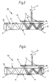
- FIG. 3 shows a schematic cross-sectional illustration of a rotation angle sensor 50 with reflective optical elements 2a, 2b, 3a, 3b caused by replication a surface 4 were generated on the base body 1.
- a tool e.g. B. a negative form
- the optical Properties determining structures pressed. These structures will be fixed by chemical, thermal or UV treatment.
- the optical Elements 2a, 2b, 3a, 3b are thus already aligned with one another when they are generated and permanently connected to the base body 1. You are on one single surface 4 of the base body 1 is arranged. The way it works is same as described under Fig.1.
- FIG. 4 shows a variant of the representation of FIG. 3, in which the optical elements 2a, 2b, 3a, 3b on two different surfaces 9 and 4 are arranged.
- the optical elements 2a, 2b, 3a, 3b are on two Different surfaces 4 and 5 arranged to the base bodies 1a and 1b belong.
- the basic bodies 1a and 1b are in the form of plates with flat surfaces educated. Basically, areas 4, 5 and 9 can be used for all Embodiments can also be curved. You can even use it as a Serve lens surfaces.
- the basic bodies 1a and 1b can be made of different materials.
- optical elements 2a, 2b, 3a and 3b both on surfaces 4 and 5 and be integrated monolithically on the surface 9. With that you can improve optical imaging properties. You can also send to the Surfaces 4 and 5 themselves additional reflections take place as they are on the Surface 9 are shown in Fig.5. Due to the number of reflections Lengths of the optical paths between the radiation source 6, optical elements 2a, 3a, the elements 3b, 2b and the detector 7 are determined. This results in an additional degree of freedom for the optical Distances of the imaging elements 2a, 2b, 3a, 3b. This can also be done by different thicknesses of the base body 1a and 1b or by use different optical material of the main body 1a and 1b happen.
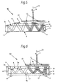
- FIG. 6 shows a schematic cross-sectional illustration of a rotation angle sensor 50 with refractive optical elements 2a, 2b, 3a, 3b, which are in a base body 1c are integrated monolithically. With these optical elements Refraction properties used for the radiation guidance.
- the basic body 1c is rigidly connected to a plate 1d via a mechanical holder 18.
- the radiation source 6 and the detector 7 are located on the underside of the Plate 1d.
- the medium 17 between the base body 1c and the plate 1d consists of air in the simplest case, but can also consist of other gaseous, liquid or solid substances with a suitable refractive index.
- the radiation from the radiation source 6 is at transitions between the Medium 17 and the base body 1c broken.
- the curved Surfaces of the refractive optical elements 2a, 2b, 3a, 3b result imaging properties. In doing so, the curvature of the surfaces lower accuracy requirements than those described above reflective optical elements is required.
- the surface 9a of the plate 1d reflects the radiation, so that a continuous beam path results. Also in this embodiment the structures 11 of the pane 10 are illuminated and the structures 11 deliver an intensity pattern 21 to the detector 7.
- the plate 1d can be replaced by one similar to the base body 1c Base body to be replaced with further optical elements 2a, 2b, 3a, 3b, see above that the monolithically integrated refractive elements 2a, 2b, 3a, 3b on two different areas are arranged.
- the Rotation angle sensor 50 with refractive optical elements 2a, 2b, 3a, 3b also all embodiments in analogy to the variants of the representations in the Figures 2 to 5 apply.
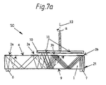
- FIG. 7a shows a schematic cross-sectional representation of a Angle of rotation sensor 50 with monolithically integrated diffractive optical Elements 2a, 2b, 3a, 3b, which are arranged on a surface 4.
- diffractive optical Elements 2a, 2b, 3a, 3b With these optical elements are their diffractive properties Radiation guidance exploited. Because of these properties, each of the diffractive elements 2a, 2b, 3a, 3b a radiation with several Diffraction orders. Differentiate the different diffraction orders themselves by their direction of radiation. A subsequent diffractive one Optical element is arranged so that it is the radiation of a Diffraction order can receive. This is shown with the solid lines in Fig. 7a symbolizes. The radiation of the other diffraction orders is either absorbs or otherwise leaves the rotation angle sensor 50 without to get to the detector 7. This case represent the dashed lines.
- FIG. 7b shows a schematic spatial Representation of the angle of rotation sensor 50.
- the offset arrangement of the Radiation source 6, the optical elements 2a, 2b, 3a, 3b, the disc 10 and of the detector 7 to each other clearly.
- optical element 2a generated and shown in dashed lines 0th order diffraction not the optical element 3a, but the radiation at least one higher diffraction order (solid lines).
- the diffraction obeys the angle of incidence and the angle of reflection of the radiation at the diffractive elements 2a, 2b, 3a, 3b not to the known reflection law reflective surfaces.
- the detector 7 should preferably only have one order of diffraction to reach.
- the diffractive optical elements 2a, 2b, 3a, 3b can also be in different Surfaces of the base body 1 be integrated monolithically analogous to the 4 and 5 (surfaces 9, 4, 5). Also an analog one 2 with an additional base plate 15 is intended for a rotation angle sensor 50 with diffractive optical elements 2a, 2b, 3a, 3b be valid.
Landscapes
- Physics & Mathematics (AREA)
- General Physics & Mathematics (AREA)
- Optical Transform (AREA)
Claims (13)
- Capteur optique (50) pour déterminer l'angle de rotation (α) d'un axe de rotation (12), aveca) une source de rayonnement optique (6), des premiers et deuxièmes éléments optiques (2a,3a;2b,3b) déviant les rayons et produisant une illustration, un détecteur (7) optoélectronique présentant une résolution locale, etb) un disque (10) structuré, disposé dans le trajet des rayons, entre les premiers et deuxièmes éléments optiques (2a,3a;2b,3b), susceptibles de tourner avec l'axe de rotation (12), et dont les structures (11) sont associées à l'angle de rotation (α), et dont les structures (11) en utilisation, sont illuminées au moins partiellement par le rayonnement venant de la source de rayonnement (6) et illustrées ou projetées sur le détecteur (7),
oùc) les éléments optiques (2a,3a;2b,3b) sont intégrés de façon monolithique en un matériau conducteur optique sur ou/et dans un corps de base (1;1a,1b;1e), faisant que le rayonnement est guidé à l'intérieur du corps de base (1;1b,1b;1c),d) dans la zone de chacun des éléments ou sur chacun des premiers et deuxièmes éléments optiques (2a,3a;2b,3b), le rayonnement est réfléchi une première fois de façon précise, ou bien seul un ordre de diffraction du rayonnement est retransmis, ete) le corps de base (1;1a,1b;1c) présente des zones de surface, desquelles, en utilisation, après les premiers éléments optiques (2a,3a) le rayonnement sort dans la direction du disque (10), et dans lesquelles, après son interaction avec les structures (11) du disque (10), le rayonnement ré-pénètre dans le corps de base (1;1a,1b;1c). - Capteur optique selon la revendication 1, caractérisé en ce que les éléments optiques (2a,2b,3a,3b) dans les corps de base (1;1a,1b;1c) sont intégrés de façon monolithique, par lithographie, par gravure chimique, fraisage, gravure mécanique, façonnage tridimensionnel, pressage d'ébauche ou par un procédé de moulage par injection.
- Capteur optique selon la revendication 1, caractérisé en ce que les éléments optiques (2a,2b,3a,3b) sont appliquées par métallisation sous vide ou bien sont répliqués sur le corps de base (1;1a,1b;1c).
- Capteur optique selon l'une des revendications précédentes, caractérisé en ce que les éléments optiques (2a,2b,3a,3b) sont des éléments à réflexion.
- Capteur optique selon l'une des revendications 1 à 3, caractérisé en ce que les éléments optiques (2a,2b,3a,3b) sont des éléments à réfraction.
- Capteur optique selon l'une des revendications là 3, caractérisé en ce que les éléments optiques (1a,2b,3a,3b) sont constitués de structures à diffraction.
- Capteur optique selon la revendication 6, caractérisé en ce que les éléments optiques (2a,2b,3a,3b) sont construits et disposés les uns par rapport aux autres de manière à ce que le rayonnement n'atteigne le détecteur (7) que depuis uniquement un ordre de diffraction.
- Capteur optique selon l'une des revendications 1 à 3, caractérisé en ce qu'une combinaison d'éléments optiques (2a,2b,3a,3b) à réflexion, réfraction ou diffraction, est intégrée de façon monolithique sur le corps de base (1;1a,1b;1c).
- Capteur optique selon l'une des revendications précédentes, caractérisé en ce que les éléments optiques (2a,2b,3a,3b) sont disposés sur une surface (4) unique du corps de base (1;1a,1b;1c).
- Capteur optique selon l'une des revendications 1 à 8, caractérisé en ce que les éléments optiques (2a,2b,3a,3b) sont disposés sur des surfaces (4,5,9) différentes du corps de base (1;1a,1b;1c).
- Capteur optique selon l'une des revendications précédentes, caractérisé en ce que les structures (11) sont intégrées de façon monolithique sur le disque (10) et présentent des propriétés de réflexion, réfraction et/ou diffraction, en ce qu'elles projettent sur le détecteur (7) un motif d'intensité (21) dépendant de l'angle de rotation (α) du disque (10).
- Capteur optique selon la revendication 11, caractérisé en ce que les structures (11) présentes sur le disque (10) ont en même temps des propriétés d'illustration.
- Capteur optique selon la revendication 11 ou la revendication 12, caractérisé en ce que, pour améliorer la précision de mesure, la fréquence de base locale ou bien une fréquence locale supérieure harmonique du motif d'intensité (21) généré par les structures (11) du disque (10) sur le détecteur (7) forme, avec la fréquence fondamentale locale des structures, sensibles au rayonnement, du détecteur (7) un motif de superposition à basse fréquence.
Applications Claiming Priority (3)
| Application Number | Priority Date | Filing Date | Title |
|---|---|---|---|
| DE19621188 | 1996-05-25 | ||
| DE19621188A DE19621188B4 (de) | 1996-05-25 | 1996-05-25 | Optischer Sensor zur Bestimmung des Drehwinkels einer Drehachse |
| PCT/EP1997/002660 WO1997045706A1 (fr) | 1996-05-25 | 1997-05-23 | Detecteur optique pour la determination de l'angle de rotation d'un axe de rotation |
Publications (2)
| Publication Number | Publication Date |
|---|---|
| EP0901611A1 EP0901611A1 (fr) | 1999-03-17 |
| EP0901611B1 true EP0901611B1 (fr) | 2002-03-27 |
Family
ID=7795363
Family Applications (1)
| Application Number | Title | Priority Date | Filing Date |
|---|---|---|---|
| EP97923995A Expired - Lifetime EP0901611B1 (fr) | 1996-05-25 | 1997-05-23 | Detecteur optique pour la determination de l'angle de rotation d'un axe de rotation |
Country Status (3)
| Country | Link |
|---|---|
| EP (1) | EP0901611B1 (fr) |
| DE (2) | DE19621188B4 (fr) |
| WO (1) | WO1997045706A1 (fr) |
Cited By (1)
| Publication number | Priority date | Publication date | Assignee | Title |
|---|---|---|---|---|
| CN106871926A (zh) * | 2016-12-30 | 2017-06-20 | 中国科学院西安光学精密机械研究所 | 大口径光电经纬仪测角精度的测量装置及测量方法 |
Families Citing this family (8)
| Publication number | Priority date | Publication date | Assignee | Title |
|---|---|---|---|---|
| DE10058239B4 (de) * | 2000-11-17 | 2012-01-26 | Dr. Johannes Heidenhain Gmbh | Positionsmeßeinrichtung |
| DE10308085B4 (de) * | 2002-03-08 | 2006-09-07 | Leuze Electronic Gmbh & Co Kg | Optoelektronische Vorrichtung |
| DE202004001443U1 (de) * | 2004-01-26 | 2005-06-02 | Hahn-Schickard-Gesellschaft für angewandte Forschung e.V. | Hochauflösender Drehwinkelgeber |
| DE102004048317A1 (de) * | 2004-10-05 | 2006-04-06 | Hengstler Gmbh | Codierte Abtastscheibe für einen Drehgeber |
| ES2322151T3 (es) | 2004-12-30 | 2009-06-17 | Delphi Technologies Inc. | Procedimiento de determinacion de la posicion de un primer elemento en movimiento relativo a un segundo elemento y dispositivo para implementar dicho procedimiento. |
| EP1995567A1 (fr) | 2007-05-24 | 2008-11-26 | Leica Geosystems AG | Procédé de mesure de position optoélectronique et dispositif de mesure de position optoélectronique |
| CH709341A1 (de) * | 2014-03-07 | 2015-09-15 | Elesta Gmbh | Vorrichtung und Verfahren zur Erfassung von Objekten in einem Überwachungsbereich. |
| AT517945B1 (de) | 2015-11-17 | 2017-06-15 | Univ Wien Tech | Sensor zur bestimmung eines drehwinkels |
Family Cites Families (8)
| Publication number | Priority date | Publication date | Assignee | Title |
|---|---|---|---|---|
| JPS57104815A (en) * | 1980-12-20 | 1982-06-30 | Asahi Optical Co Ltd | Angle measuring apparatus employing line sensor |
| CH658514A5 (de) * | 1982-02-09 | 1986-11-14 | Wild Heerbrugg Ag | Verfahren und vorrichtung zur erfassung einer messgroesse. |
| DE3609211A1 (de) * | 1986-03-19 | 1987-09-24 | Rudolf Epple | Optischer winkelgeber |
| FR2615281B1 (fr) * | 1987-05-11 | 1996-08-23 | Canon Kk | Dispositif de mesure d'une distance en mouvement relatif de deux objets mobiles l'un par rapport a l'autre |
| DE3930303A1 (de) * | 1989-09-11 | 1991-03-14 | Litton Precision Prod Int | Elektrooptische abtasteinheit fuer ein laengen- oder winkelmessgeraet |
| DE4113046C2 (de) * | 1991-04-22 | 1994-02-10 | Zeiss Carl Jena Gmbh | Optoelektronisches Positionsmeßgerät |
| JP3478567B2 (ja) * | 1992-09-25 | 2003-12-15 | キヤノン株式会社 | 回転情報検出装置 |
| JP3173208B2 (ja) * | 1993-01-29 | 2001-06-04 | キヤノン株式会社 | 変位測定装置 |
-
1996
- 1996-05-25 DE DE19621188A patent/DE19621188B4/de not_active Expired - Fee Related
-
1997
- 1997-05-23 WO PCT/EP1997/002660 patent/WO1997045706A1/fr not_active Ceased
- 1997-05-23 EP EP97923995A patent/EP0901611B1/fr not_active Expired - Lifetime
- 1997-05-23 DE DE59706773T patent/DE59706773D1/de not_active Expired - Lifetime
Cited By (2)
| Publication number | Priority date | Publication date | Assignee | Title |
|---|---|---|---|---|
| CN106871926A (zh) * | 2016-12-30 | 2017-06-20 | 中国科学院西安光学精密机械研究所 | 大口径光电经纬仪测角精度的测量装置及测量方法 |
| CN106871926B (zh) * | 2016-12-30 | 2019-08-06 | 中国科学院西安光学精密机械研究所 | 大口径光电经纬仪测角精度的测量装置及测量方法 |
Also Published As
| Publication number | Publication date |
|---|---|
| WO1997045706A1 (fr) | 1997-12-04 |
| DE59706773D1 (de) | 2002-05-02 |
| DE19621188B4 (de) | 2005-07-14 |
| EP0901611A1 (fr) | 1999-03-17 |
| DE19621188A1 (de) | 1997-11-27 |
Similar Documents
| Publication | Publication Date | Title |
|---|---|---|
| DE69836441T2 (de) | Axialer led-positionsgeber zur messung der winkellage eines rotierenden gliedes | |
| DE102007007311B4 (de) | Abtasteinheit für eine Positionsmesseinrichtung zur Detektion von optischen Maßverkörperungen sowie entsprechende Positionsmesseinrichtung | |
| DE68928192T2 (de) | Vorrichtung und Verfahren zur Positionsdetektion | |
| DE69322569T2 (de) | Vorrichtung zur Erfassung von Rotationsinformationen | |
| EP2150780B1 (fr) | Procédé et dispositif optoélectronique de mesure de position | |
| EP2394143B1 (fr) | Dispositif et procédé optoélectroniques de mesure de position | |
| DE19856106A1 (de) | Reflektor zur Entfernungsmessung | |
| EP0901611B1 (fr) | Detecteur optique pour la determination de l'angle de rotation d'un axe de rotation | |
| EP0978708A1 (fr) | Codeur rotatif | |
| EP0901608B1 (fr) | Detecteur optique pour la determination d'un angle d'inclinaison | |
| DE69122218T2 (de) | Verschiebungsdetektor | |
| EP4390447B1 (fr) | Capteur optoélectronique et procédé de fabrication d'un capteur optoélectronique | |
| JPH01272917A (ja) | 反射式xyエンコーダ | |
| DE60021770T2 (de) | Messkopf | |
| EP0901639B1 (fr) | Procede et dispositif pour la determination de la direction dans laquelle se trouve un objet | |
| EP2823263B1 (fr) | Dispositif de mesure de position optoélectrique | |
| DE69616141T2 (de) | Elektro-optischer Sensor für die Winkelposition einer Welle | |
| DE19621196C2 (de) | Optischer Sensor zum Verfolgen einer Zielmarke | |
| EP0626564A1 (fr) | Dispositif de mesure d'angles ou de longueur | |
| DE4113046C2 (de) | Optoelektronisches Positionsmeßgerät | |
| DE9209777U1 (de) | Lichtelektrische Längen- oder Winkelmeßeinrichtung | |
| DE102005033852A1 (de) | Scheibenförmiges Trägersystem mit einer Mehrzahl integrierter Beugungsstrukturen | |
| EP1293758A1 (fr) | Corps de mesure pour des systèmes de mesure de position | |
| DD272916A1 (de) | Inkrementales laengenmesssystem mit lichtleitern | |
| DE9218399U1 (de) | Längen- oder Winkelmeßsystem |
Legal Events
| Date | Code | Title | Description |
|---|---|---|---|
| PUAI | Public reference made under article 153(3) epc to a published international application that has entered the european phase |
Free format text: ORIGINAL CODE: 0009012 |
|
| 17P | Request for examination filed |
Effective date: 19981013 |
|
| AK | Designated contracting states |
Kind code of ref document: A1 Designated state(s): CH DE FR GB LI |
|
| GRAG | Despatch of communication of intention to grant |
Free format text: ORIGINAL CODE: EPIDOS AGRA |
|
| 17Q | First examination report despatched |
Effective date: 20010705 |
|
| GRAG | Despatch of communication of intention to grant |
Free format text: ORIGINAL CODE: EPIDOS AGRA |
|
| GRAH | Despatch of communication of intention to grant a patent |
Free format text: ORIGINAL CODE: EPIDOS IGRA |
|
| GRAH | Despatch of communication of intention to grant a patent |
Free format text: ORIGINAL CODE: EPIDOS IGRA |
|
| GRAH | Despatch of communication of intention to grant a patent |
Free format text: ORIGINAL CODE: EPIDOS IGRA |
|
| REG | Reference to a national code |
Ref country code: GB Ref legal event code: IF02 |
|
| GRAA | (expected) grant |
Free format text: ORIGINAL CODE: 0009210 |
|
| AK | Designated contracting states |
Kind code of ref document: B1 Designated state(s): CH DE FR GB LI |
|
| REG | Reference to a national code |
Ref country code: CH Ref legal event code: EP |
|
| REF | Corresponds to: |
Ref document number: 59706773 Country of ref document: DE Date of ref document: 20020502 |
|
| REG | Reference to a national code |
Ref country code: CH Ref legal event code: NV Representative=s name: BUECHEL, KAMINSKI & PARTNER PATENTANWAELTE ESTABLI |
|
| GBT | Gb: translation of ep patent filed (gb section 77(6)(a)/1977) |
Effective date: 20020618 |
|
| ET | Fr: translation filed | ||
| ET | Fr: translation filed | ||
| PLBE | No opposition filed within time limit |
Free format text: ORIGINAL CODE: 0009261 |
|
| STAA | Information on the status of an ep patent application or granted ep patent |
Free format text: STATUS: NO OPPOSITION FILED WITHIN TIME LIMIT |
|
| 26N | No opposition filed |
Effective date: 20021230 |
|
| REG | Reference to a national code |
Ref country code: CH Ref legal event code: PFA Owner name: LEICA GEOSYSTEMS AG Free format text: LEICA GEOSYSTEMS AG# #9435 HEERBRUGG (CH) -TRANSFER TO- LEICA GEOSYSTEMS AG# #9435 HEERBRUGG (CH) |
|
| REG | Reference to a national code |
Ref country code: FR Ref legal event code: PLFP Year of fee payment: 19 |
|
| PGFP | Annual fee paid to national office [announced via postgrant information from national office to epo] |
Ref country code: GB Payment date: 20150521 Year of fee payment: 19 Ref country code: CH Payment date: 20150521 Year of fee payment: 19 Ref country code: DE Payment date: 20150521 Year of fee payment: 19 |
|
| PGFP | Annual fee paid to national office [announced via postgrant information from national office to epo] |
Ref country code: FR Payment date: 20150521 Year of fee payment: 19 |
|
| REG | Reference to a national code |
Ref country code: DE Ref legal event code: R119 Ref document number: 59706773 Country of ref document: DE |
|
| REG | Reference to a national code |
Ref country code: CH Ref legal event code: PL |
|
| GBPC | Gb: european patent ceased through non-payment of renewal fee |
Effective date: 20160523 |
|
| PG25 | Lapsed in a contracting state [announced via postgrant information from national office to epo] |
Ref country code: CH Free format text: LAPSE BECAUSE OF NON-PAYMENT OF DUE FEES Effective date: 20160531 Ref country code: LI Free format text: LAPSE BECAUSE OF NON-PAYMENT OF DUE FEES Effective date: 20160531 |
|
| REG | Reference to a national code |
Ref country code: FR Ref legal event code: ST Effective date: 20170131 |
|
| PG25 | Lapsed in a contracting state [announced via postgrant information from national office to epo] |
Ref country code: FR Free format text: LAPSE BECAUSE OF NON-PAYMENT OF DUE FEES Effective date: 20160531 Ref country code: DE Free format text: LAPSE BECAUSE OF NON-PAYMENT OF DUE FEES Effective date: 20161201 |
|
| PG25 | Lapsed in a contracting state [announced via postgrant information from national office to epo] |
Ref country code: GB Free format text: LAPSE BECAUSE OF NON-PAYMENT OF DUE FEES Effective date: 20160523 |