EP0901677B1 - Dispositif pour determiner la qualite d'un signal de sortie devant etre genere par un circuit de traitement de signaux, et procede associe - Google Patents
Dispositif pour determiner la qualite d'un signal de sortie devant etre genere par un circuit de traitement de signaux, et procede associe Download PDFInfo
- Publication number
- EP0901677B1 EP0901677B1 EP97927046A EP97927046A EP0901677B1 EP 0901677 B1 EP0901677 B1 EP 0901677B1 EP 97927046 A EP97927046 A EP 97927046A EP 97927046 A EP97927046 A EP 97927046A EP 0901677 B1 EP0901677 B1 EP 0901677B1
- Authority
- EP
- European Patent Office
- Prior art keywords
- signal
- arrangement
- quality
- time
- output
- Prior art date
- Legal status (The legal status is an assumption and is not a legal conclusion. Google has not performed a legal analysis and makes no representation as to the accuracy of the status listed.)
- Expired - Lifetime
Links
Images

Classifications
-
- G—PHYSICS
- G10—MUSICAL INSTRUMENTS; ACOUSTICS
- G10L—SPEECH ANALYSIS TECHNIQUES OR SPEECH SYNTHESIS; SPEECH RECOGNITION; SPEECH OR VOICE PROCESSING TECHNIQUES; SPEECH OR AUDIO CODING OR DECODING
- G10L25/00—Speech or voice analysis techniques not restricted to a single one of groups G10L15/00 - G10L21/00
- G10L25/48—Speech or voice analysis techniques not restricted to a single one of groups G10L15/00 - G10L21/00 specially adapted for particular use
- G10L25/69—Speech or voice analysis techniques not restricted to a single one of groups G10L15/00 - G10L21/00 specially adapted for particular use for evaluating synthetic or decoded voice signals
Definitions
- the invention relates to a device for determining the quality of an output signal to be generated by a signal processing circuit with respect to a reference signal, which device comprises a first series circuit having a first input for receiving the output signal, a second series circuit having a second input for receiving the reference signal, and a combining circuit, coupled to a first output of the first series circuit and to a second output of the second series circuit, for generating a quality signal at an output of the combining circuit, which first series circuit is provided with
- Such a device is disclosed in the first reference: J. Audio Eng. Soc., Vol. 40, No. 12, December 1992, in particular "A Perceptual Audio Quality Measure Based on a Psychoacoustic Sound Representation" by John G. Beerends and Jan A. Stemerdink, pages 963 - 978, more particularly Figure 7.
- the device described therein determines the quality of an output signal to be generated by a signal processing circuit, such as, for example, a coder/decoder, or codec, with respect to a reference signal.
- Said reference signal is, for example, an input signal to be presented to the signal processing circuit, although the possibilities also include using as reference signal a pre-calculated ideal version of the output signal.
- the first signal parameter is generated as a function of time and frequency by means of the first signal processing arrangement, associated with the first series circuit, in response to the output signal, after which the first signal parameter is compressed by means of the first compressing arrangement associated with the first series circuit.
- intermediate operational processing of said first signal parameter should not be ruled out at all.
- the second signal parameter is compressed by means of the second compressing arrangement associated with the second series circuit in response to the reference signal. In this connection, too, further operational processing of said second signal parameter should not be ruled out at all.
- the differential signal is determined by means of the differential arrangement associated with the combining circuit, after which the quality signal is generated by integrating the differential signal with respect to frequency by means of the integrating arrangement associated with the combining circuit and by then integrating the integrated differential signal with respect to time by means of the time-averaging arrangement associated with the combining circuit.
- Such a device has, inter alia, the disadvantage that the objective quality signal to be assessed by means of said device and a subjective quality signal to be assessed by human observers have a poor correlation.
- the object of the invention is, inter alia, to provide a device of the type mentioned in the preamble, the objective quality signal to be assessed by means of said device and a subjective quality signal to be assessed by human observers having a better correlation.
- the device according to the invention has the characteristic that the combining circuit is further provided with
- the invention is based, inter alia, on the insight that the poor correlation between objective quality signals to be assessed by means of known devices and subjective quality signals to be assessed by human observers is the consequence, inter alia, of the fact that certain distortions are found to be more objectionable by human observers than other distortions, and is further based, inter alia, on the insight that, inside the combining circuit, some (time-intervals of) signals are more relevant than other (time-intervals of) signals.
- the problem of the poor correlation is thus solved by distinguishing more relevant signals from less relevant signals.
- a first embodiment of the device according to the invention has the characteristic that the comparing arrangement and the selecting arrangement are situated between the integrating arrangement and the time-averaging arrangement for comparing, per time-interval, the output signal of the integrating arrangement with the other signal having a predefined value and for in case the output signal of the integrating arrangement being larger than the other signal supplying the output signal of the integrating arrangement to the time-averaging arrangement and for in case the output signal of the integrating arrangement being smaller than the other signal not supplying the output signal of the integrating arrangement to the time-averaging arrangement.
- the integrated differential signal can be compared with the other signal having a predefined value.
- a second embodiment of the device has the characteristic that the time-averaging arrangement is arranged for producing at a first output a first quality signal associated with a left channel of the signal processing circuit and at a second output a second quality signal associated with a right channel of the signal processing circuit, and in that the comparing arrangement and the selecting arrangement are coupled to the first and second outputs of the time-averaging arrangement for comparing the first quality signal with the second quality signal, and for selecting the quality signal having the largest value.
- a quality signal associated with a left channel of the signal processing circuit can be compared with a quality signal associated with a right channel of the signal processing circuit and the quality signal having the largest value can be selected. Due to the fact that according to this embodiment the signal processing circuit has got a left and a right channel, two quality signals will have to be determined: one for the left channel, and one for the right channel. This can be done by either letting the device according to the invention determine the quality of an entire left output signal and then letting said device determine the quality of an entire right output signal, or by, per time-interval, letting said device determine the quality of the left and right output signals.
- a third embodiment of the device according to the invention has the characteristic that in case the second quality signal being larger than a sum of the first quality signal and a signal having a further predefined value, the second quality signal is selected and in case the second quality signal being smaller than a sum of the first quality signal and the signal having the further predefined value the first quality signal is selected.
- the quality signal associated with the right channel being larger than a sum of the quality signal associated with the left channel and a signal having a further predefined value the quality signal associated with the right channel is selected and in case the quality signal associated with the right channel being smaller than a sum of the quality signal associated with the left channel and the signal having the further predefined value the quality signal associated with the left channel is selected, the greater relevance of the left output signal of the signal processing circuit with respect to the right output signal is stressed.
- a fourth embodiment of the device according to the invention has the characteristic that the selecting arrangement is provided with a multiplying arrangement for multiplying the selected quality signal with a signal having a value which depends upon at least a correlation between integrated differential signals associated with the left channel and integrated differential signals associated with the right channel.
- the selecting arrangement with a multiplying arrangement for multiplying the selected quality signal with a signal having a value which depends upon at least a correlation between integrated differential signals associated with the left channel and integrated differential signals associated with the right channel, a very good correlation is obtained between the objective quality signal to be assessed by means of said device and a subjective quality signal to be assessed by human observers.
- first embodiment on the one hand and the second, third and fourth embodiment on the other hand can be regarded to be independent embodiments, the best correlation will be obtained in case the first, second, third and fourth embodiments are used together.
- a fifth embodiment of the device according to the invention has the characteristic that the second series circuit is furthermore provided with
- the second signal parameter is generated as a function of both time and frequency.
- the input signal to be presented to the signal processing circuit such as, for example, a coder/decoder, or codec, whose quality is to be determined, is used as reference signal, in contrast to when a second signal processing arrangement is not used, in which case a pre-calculated ideal version of the output signal should be used as reference signal.
- a sixth embodiment of the device according to the invention has the characteristic that a signal processing arrangement is provided with
- the signal parameter is generated as a function of time and frequency by the first and/or second signal processing arrangement as a result of using the multiplying arrangement and the transforming arrangement, which transforming arrangement also performs, for example, the absolute-value determination.
- a seventh embodiment of the device according to the invention has the characteristic that a signal processing arrangement is provided with
- the signal parameter is generated as a function of time and frequency by the first and/or second signal processing arrangement as a result of using the subband filtering arrangement which also performs, for example, the absolute-value determination.
- An eighth embodiment of the device according to the invention has the characteristic that the signal processing arrangement is furthermore provided with
- the signal parameter generated by the first and/or second signal processing arrangement and represented by means of a time spectrum and a frequency spectrum is converted into a signal parameter represented by means of a time spectrum and a Bark spectrum by using the converting arrangement.
- the invention furthermore relates to a method for determining the quality of an output signal to be generated by a signal processing circuit with respect to a reference signal, which method comprises the following steps of
- the method according to the invention has the characteristic that the step of generating the quality signal comprises the following substeps of
- a first embodiment of the method according to the invention has the characteristic that the substep of comparing includes comparing, per time-interval, the differential signal which has been integrated with respect to frequency with the other signal having a predefined value and in case the integrated differential signal being larger than the other signal integrating said integrated differential signal with respect to time and in case the differential signal which has been integrated with respect to frequency being smaller than the other signal not integrating said integrated differential signal with respect to time.
- a second embodiment of the method according to the invention has the characteristic that the step of of generating the quality signal comprises the further substep of producing a first quality signal associated with a left channel of the signal processing circuit and a second quality signal associated with a right channel of the signal processing circuit, and that the substep of comparing includes comparing the first quality signal with the second quality signal, and the substep of making a selection includes selecting the quality signal having the largest value.
- a third embodiment of the method according to the invention has the characteristic that in case the second quality signal being larger than a sum of the first quality signal and a signal having a further predefined value the second quality signal is selected and in case the second quality signal being smaller than a sum of the first quality signal and the signal having the further predefined value the first quality signal is selected.
- a fourth embodiment of the method according to the invention has the characteristic that the selected quality signal is multiplied with a signal having a value which depends upon at least a correlation between differential signals which have been integrated with respect to frequency and associated with the left channel and differential signals which have been integrated with respect to frequency and associated with the right channel.
- a fifth embodiment of the method according to the invention has the characteristic that the step of generating a second compressed signal parameter in response to the reference signal comprises the following substeps of
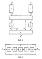
- the device according to the invention shown in Figure 1 comprises a first signal processing arrangement 1 having a first input 7 for receiving an output signal originating from a signal processing circuit such as, for example, a coder/decoder, or codec.
- a first output of first signal processing arrangement 1 is connected via a coupling 9 to a first input of a scaling circuit 3.
- the device according to the invention furthermore comprises a second signal processing arrangement 2 having a second input 8 for receiving an input signal to be fed to the signal processing circuit such as, for example, the coder/decoder, or codec.
- a second output of second signal processing arrangement 2 is connected via a coupling 10 to a second input of scaling circuit 3.
- a first output of scaling circuit 3 is connected via a coupling 11 to a first input of a first compressing arrangement 4, and a second output of scaling circuit 3 is connected via a coupling 12 to a second input of a second compressing arrangement 5.
- a first output of first compressing arrangement 4 is connected via a coupling 13 to a first input of a combining circuit 6, and a second output of second compressing arrangement 5 is connected via a coupling 16 to a second input of combining circuit 6.
- a third output of scaling circuit 3 is connected via a coupling 14 to a third input of combining circuit 6, and the second output of second compressing arrangement 5, or coupling 16, is connected via a coupling 15 to a fourth input of combining circuit 6 which has an output 17 for generating a quality signal.
- First signal processing arrangement 1 and first compressing arrangement 4 jointly correspond to a first series circuit
- second signal processing arrangement 2 and second compressing arrangement 5 jointly correspond to a second series circuit.
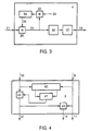
- the known first (or second) signal processing arrangement 1 (or 2) shown in Figure 2 comprises a first (or second) multiplying arrangement 20 for multiplying in the time domain the output signal (or input signal) to be fed to the first input 7 (or second input 8) of the first (or second) signal processing arrangement 1 (or 2) and originating from the signal processing circuit such as, for example, the coder/decoder, or codec, by a window function, a first (or second) transforming arrangement 21, coupled to the first (or second) multiplying arrangement 20, for transforming the signal originating from the first (or second) multiplying arrangement 20 to the frequency domain, a first (or second) absolute-value arrangement 22 for determining the absolute value of the signal originating from the first (or second) transforming arrangement 21 for generating a first (or second) positive signal parameter as a function of time and frequency, a first (or second) converting arrangement 23 for converting the first (or second) positive signal parameter originating from the first (or second) absolute-value arrangement 22 and represented by means of a time spectrum and
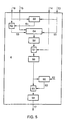
- the known first (or second) compressing arrangement 4 (or 5) shown in Figure 3 receives via coupling 11 (or 12) a signal parameter which is fed to a first (or second) input of a first (or second) adder 30, a first (or second) output of which is connected via a coupling 31, on the one hand, to a first (or second) input of a first (or second) multiplier 32 and, on the other hand, to a first (or second) nonlinear convoluting arrangement 36 which is furthermore connected to a first (or second) compressing unit 37 for generating via coupling 13 (or 16) a first (or second) compressed signal parameter.
- First (or second) multiplier 32 has a further first (or second) input for receiving a feed signal and has a first (or second) output which is connected to a first (or second) input of a first (or second) delay arrangement 34, a first (or second) output of which is coupled to a further first (or second) input of the first (or second) adder 30.
- the scaling circuit 3 shown in Figure 4 comprises a further integrating arrangement 40, a first input of which is connected to the first input of scaling circuit 3 and consequently to coupling 9 for receiving a first series circuit signal (the first signal parameter represented by means of a time spectrum and a Bark spectrum) and a second input of which is connected to the second input of scaling circuit 3 and consequently to coupling 10 for receiving a second series circuit signal (the second signal parameter represented by means of a time spectrum and a Bark spectrum).
- a first output of further integrating arrangement 40 for generating the integrated first series circuit signal is connected to a first input of a further comparing arrangement 41 and a second output of further integrating arrangement 40 for generating the integrated second series circuit signal is connected to a second input of further comparing arrangement 41.
- the first input of scaling circuit 3 is connected to the first output and, via scaling circuit 3, coupling 9 is consequently connected through to coupling 11.
- the second input of scaling circuit 3 is connected to a first input of a further scaling unit 42 and a second output is connected to an output of further scaling unit 42 and, via scaling circuit 3, coupling 10 is consequently connected through to coupling 12 via further scaling unit 42.
- An output of further comparing arrangement 41 for generating a control signal is connected to a control input of further scaling unit 42.
- the first input of scaling circuit 3, or coupling 9 or coupling 11 is connected to a first input of a ratio-determining arrangement 43 and the output of further scaling unit 42, or coupling 12, is connected to a second input of ratio-determining arrangement 43, an output of which is connected to the third output of scaling circuit 3 and consequently to coupling 14 for generating a further scaling signal.
- the combining circuit 6 shown in Figures 5 and 6 comprises a still further comparing arrangement 50, a first input of which is connected to the first input of combining circuit 6 for receiving the first compressed signal parameter via coupling 13 and a second input of which is connected to the second input of combining circuit 6 for receiving the second compressed signal parameter via coupling 16.
- the first input of combining circuit 6 is furthermore connected to a first input of a differential arrangement 54,56.
- An output of still further comparing arrangement 50 for generating a scaling signal is connected via a coupling 51 to a control input of scaling arrangement 52, an input of which is connected to the second input of combining circuit 6 for receiving the second compressed signal parameter via coupling 16 and an output of which is connected via a coupling 53 to a second input of differential arrangement 54,56 for determining a differential signal on the basis of the mutually scaled compressed signal parameters.
- a third input of the differential arrangement 54,56 is connected to the fourth input of the combining circuit 6 for receiving, via coupling 15, the second compressed signal parameter to be received via coupling 16.
- Differential arrangement 54,56 comprises a differentiator 54 for generating a differential signal and a further absolute-value arrangement 56 for determining the absolute value of the differential signal, an output of which is connected to an input of scaling unit 57, a control input of which is connected to the third input of combining circuit 6 for receiving the further scaling signal via coupling 14.
- An output of scaling unit 57 is connected to an input of an integrating arrangement 58 for integrating the scaled absolute value of the differential signal with respect to frequency.
- an output of integrating arrangement 58 is coupled to an input of selecting arrangement 61 and to a first input of comparing arrangement 60.
- a second input of comparing arrangement 60 is coupled to a connection 62 for receiving an other signal having a predefined value.
- An output of comparing arrangement 60 is coupled, via a connection 63, to a control input of selecting arrangement 61.
- An output of selecting arrangement 61 is coupled to an input of a time-averaging arrangement 59, an output of which is connected to the output 17 of combining circuit 6 for generating the quality signal.
- an output of integrating arrangement 58 is coupled to an input of a time-averaging arrangement 59, of which a first output is connected via a connection 72 to a first input of selecting arrangement 71 and a second output is connected via a connection 73 to a second input of selecting arrangement 71.
- the output of integrating arrangement 58 is also coupled to a third input of selecting arrangement 71 via a connection 75.
- the respective first and second outputs of time-averaging arrangement 59 are further coupled via the respective connections 72 and 73 to respective first and second inputs of comparing arrangement 70, of which an output is coupled via a connection 74 to a control input of selecting arrangement 71, of which an output is connected to the output 17 of combining circuit 6 for generating the quality signal.
- a standard device for determining the quality of the output signal to be generated by the signal processing circuit such as, for example, the coder/decoder, or codec, which standard device is formed without the scaling circuit 3 shown in greater detail in Figure 4, the couplings 10 and 12 consequently being mutually connected through, and which known device is formed using a standard combining circuit 6, the third input of differential arrangement 54,56 and scaling unit 57 and the comparing arrangement 60 and/or 70 and selecting arrangement 61 and/or 71, shown in greater detail in Figures 5 and 6, consequently being missing, is as follows and, indeed, as also described in the first reference.
- the output signal of the signal processing circuit such as, for example, the coder/decoder, or codec, is fed to input 7, after which the first signal processing circuit 1 converts said output signal into a first signal parameter represented by means of a time spectrum and a Bark spectrum.
- first multiplying arrangement 20 which multiplies the output signal represented by means of a time spectrum by a window function represented by means of a time spectrum, after which the signal thus obtained and represented by means of a time spectrum is transformed by means of first transforming arrangement 21 to the frequency domain, for example by means of an FFT, or fast Fourier transform, after which the absolute value of the signal thus obtained and represented by means of a time spectrum and a frequency spectrum is determined by means of the first absolute-value arrangement 22, for example by squaring, after which the signal parameter thus obtained and represented by means of a time spectrum and a frequency spectrum is converted by means of first converting arrangement 23 into a signal parameter represented by means of a time spectrum and a Bark spectrum, for example by resampling on the basis of a nonlinear frequency scale, also referred to as Bark scale, which signal parameter is then adjusted by means of first discounting arrangement 24 to a hearing function, or is filtered, for example by multiplying by a characteristic represented by means of a Bark spectrum.
- the first signal parameter thus obtained and represented by means of a time spectrum and a Bark spectrum is then converted by means of the first compressing arrangement 4 into a first compressed signal parameter represented by means of a time spectrum and a Bark spectrum.
- the input signal of the signal processing circuit such as, for example, the coder/decoder, or codec
- the second signal processing circuit 2 converts said input signal into a second signal parameter represented by means of a time spectrum and a Bark spectrum, and the latter is converted by means of the second compressing arrangement 5 into a second compressed signal parameter represented by means of a time spectrum and a Bark spectrum.
- the first and second compressed signal parameters are then fed via the respective couplings 13 and 16 to combining circuit 6, it being assumed for the time being that this is a standard combining circuit which lacks the third input of differential arrangement 54,56 and scaling unit 57 shown in greater detail in Figure 5.
- the two compressed signal parameters are integrated by still further comparing arrangement 50 and mutually compared, after which still further comparing arrangement 50 generates the scaling signal which represents, for example, the average ratio between the two compressed signal parameters.
- Said scaling signal is fed to scaling arrangement 52 which, in response thereto, scales the second compressed signal parameter (that is to say, increases or reduces it as a function of the scaling signal).
- scaling arrangement 52 could also be used, in a manner known to the person skilled in the art, for scaling the first compressed signal parameter instead of for scaling the second compressed signal parameter and use could furthermore be made, in a manner known to the person skilled in the art, of two scaling arrangements for mutually scaling the two compressed signal parameters at the same time.
- the differential signal is derived by means of differentiator 54 from the mutually scaled compressed signal parameters, the absolute value of which differential signal is then determined by means of further absolute-value arrangement 56.
- the signal thus obtained is integrated by means of integrator 58 with respect to a Bark spectrum and is integrated by means of time-averaging arrangement 59 with respect to a time spectrum and generated by means of output 17 as quality signal which indicates in an objective manner the quality of the signal processing circuit such as, for example, the coder/decoder or codec.
- an improved device for determining the quality of the output signal to be generated by the signal processing circuit such as, for example, the coder/decoder, or codec
- the signal processing circuit such as, for example, the coder/decoder, or codec
- the first series circuit signal (the first signal parameter represented by means of a time spectrum and a Bark spectrum) to be received via coupling 9 and the first input of scaling circuit 3 is fed to the first input of further integrating arrangement 40 and the second series circuit signal (the second signal parameter represented by means of a time spectrum and a Bark spectrum) to be received via the coupling 10 and the second input of scaling circuit 3 is fed to the second input of further integrating arrangement 40, which integrates the two series circuit signals with respect to frequency, after which the integrated first series circuit signal is fed via the first output of further integrating arrangement 40 to the first input of further comparing arrangement 41 and the integrated second series circuit signal is fed via the second output of further integrating arrangement 40 to the second input of further comparing arrangement 41.
- the latter compares the two integrated series circuit signals and generates, in response thereto, the control signal which is fed to the control input of further scaling unit 42.
- the latter scales the second series circuit signal (the second signal parameter represented by means of a time spectrum and a Bark spectrum) to be received via coupling 10 and the second input of scaling circuit 3 as a function of said control signal (that is to say increases or reduces the amplitude of said second series circuit signal) and generates [sic] the thus scaled second series circuit signal via the output of further scaling unit 42 to the second output of scaling circuit 3, while the first input of scaling arrangement 3 is connected through in this example in a direct manner to the first output of scaling circuit 3.
- the first series circuit signal and the scaled second series circuit signal respectively are passed via scaling circuit 3 to first compressing arrangement 4 and second compressing arrangement 5, respectively.
- ratio-determining arrangement 43 is capable of assessing the mutual ratio of the first series circuit signal and the scaled second series circuit signal and of generating a further scaling signal as a function thereof by means of the output of ratio-determining arrangement 43, which further scaling signal is fed via the third output of scaling circuit 3 and consequently via coupling 14 to the third input of combining circuit 6.
- Said further scaling signal is fed in combining circuit 6 to scaling unit 57 which scales, as a function of said further scaling signal, the absolute value of the differential signal originating from the differential arrangement 54,56 (that is to say increases or reduces the amplitude of said absolute value).
- scaling unit 57 which scales, as a function of said further scaling signal, the absolute value of the differential signal originating from the differential arrangement 54,56 (that is to say increases or reduces the amplitude of said absolute value).
- differentiator 54 or further absolute-value arrangement 56
- a further adjusting arrangement not shown in the figures, for example in the form of a subtracting circuit which somewhat reduces the amplitude of the differential signal.
- the amplitude of the differential signal is reduced as a function of a series circuit signal, just as in this example it is reduced as a function of the scaled and compressed second signal parameter originating from second compressing arrangement 5, as a result of which integrating arrangement 58 and time-averaging arrangement 59 function still better.
- the already very good correlation is improved still further.
- ratio-determining arrangement 43 could also be placed between couplings 13 and 16 (in other words between compressing arrangements 4 and 5, on the one hand, and combining circuit 6 on the other hand). In this case, the correlation is improved by using the results of both compressing arrangements 4 and 5 in a better way.
- a device for determining the quality of the output signal to be generated by the signal processing circuit such as, for example, the coder/decoder, or codec, which device according to the invention is consequently formed with either at least the first embodiment of the combining circuit 6 shown in greater detail in Figure 5 and comprising comparing arrangement 60 and selecting arrangement 70, or at least the second embodiment of the combining circuit 6 shown in greater detail in Figure 6 and comprising comparing arrangement 61 and selecting arrangement 71, is as described above, supplemented by what follows.
- the differential signal which has been integrated with respect to frequency by integrating arrangement 58 is supplied to comparing arrangement 60 and selecting arrangement 61.
- Comparing arrangement 60 compares, for each time-interval of for example 40 msec., a value of said signal with an other signal having a predefined value.
- comparing arrangement 60 controls selecting arrangement 61 such that the integrated differential signal is supplied (or multiplied by a large number) to time-averaging arrangement 59.
- comparing arrangement 60 controls selecting arrangement 61 such that the integrated differential signal is not supplied (or multiplied by a small number) to time-averaging arrangement 59. Due to this, the greater relevance of (time-intervals of) signals indicating much distortion is stressed with respect to (time-intervals of) signals indicating little distortion, which results in better correlation.
- the differential signal which has been integrated with respect to frequency by integrating arrangement 58 is supplied to time-averaging arrangement 59 and to the third input of selecting arrangement 71.
- Time-averaging arrangement generates two quality signals, a first quality signal associated with a left channel of the signal processing circuit, and a second quality signal associated with a right channel of the signal processing circuit. This can be done by either letting the device according to the invention determine the quality of an entire left output signal and then letting said device determine the quality of an entire right output signal, or by, per time-interval (of for example 10 sec.), letting said device determine the quality of firstly the left and secondly the right output signals.
- per time-interval of for example 10 sec.
- Comparing arrangement 70 compares these two quality signals.
- the selecting arrangement 71 is controlled such that the second quality signal associated with the right channel is selected.
- the selecting arrangement 71 is controlled such that the first quality signal associated with the left channel is selected.
- the selected quality signal is multiplied with a signal for example having a value (1.2-c) 4 which depends upon at least a correlation (c) between integrated differential signals associated with the left channel and integrated differential signals associated with the right channel.
- selecting arrangement 70 comprises for example a multiplying arrangement for multiplying the selected quality signal with said value, and a correlating arrangement for correlating both integrated differential signals, and a memory for storing integrated differential signals. Due to this, the disturbance of distortions causing binaural image shift is stressed.
- first signal processing arrangement 1 The components shown in Figure 2 of first signal processing arrangement 1 are described, as stated earlier, adequately and in a manner known to the person skilled in the art in the first reference.
- a digital output signal which originates from the signal processing circuit such as, for example, the coder/decoder, or codec, and which is, for example, discrete both in time and in amplitude is multiplied by means of first multiplying arrangement 20 by a window function such as, for example, a so-called cosine square function represented by means of a time spectrum, after which the signal thus obtained and represented by means of a time spectrum is transformed by means of first transforming arrangement 21 to the frequency domain, for example by an FFT, or fast Fourier transform, after which the absolute value of the signal thus obtained and represented by means of a time spectrum and a frequency spectrum is determined by means of the first absolute-value arrangement 22, for example by squaring.
- a window function such as, for example, a so-called cosine square function represented by means of a time spectrum
- a power density function per time/frequency unit is thus obtained.
- An alternative way of obtaining said signal is to use a subband filtering arrangement for filtering the digital output signal, which subband filtering arrangement generates, after determining an absolute value, a signal parameter as a function of time and frequency in the form of the power density function per time/frequency unit.
- First converting arrangement 23 converts said power density function per time/frequency unit, for example by resampling on the basis of a nonlinear frequency scale, also referred to as Bark scale, into a power density function per time/Bark unit, which conversion is described comprehensively in Appendix A of the first reference, and first discounting arrangement 24 multiplies said power density function per time/Bark unit, for example by a characteristic, represented by means of a Bark spectrum, for performing an adjustment on a hearing function.
- a nonlinear frequency scale also referred to as Bark scale
- first compressing arrangement 4 The components, shown in Figure 3, of first compressing arrangement 4 are, as stated earlier, described adequately and in a manner known to the person skilled in the art in the first reference.
- the power density function per time/Bark unit adjusted to a hearing function is multiplied by means of multiplier 32 by an exponentially decreasing signal such as, for example, exp ⁇ -T/ ⁇ (z) ⁇ .
- T is equal to 50% of the length of the window function and consequently represents half of a certain time interval, after which certain time interval first multiplying arrangement 20 always multiplies the output signal by a window function represented by means of a time spectrum (for example, 50% of 40 msec is 20 msec).
- ⁇ (z) is a characteristic which is represented by means of the Bark spectrum and is shown in detail in Figure 6 of the first reference.
- First delay arrangement 34 delays the product of this multiplication by a delay time of length T, or half of the certain time interval.
- First nonlinear convolution arrangement 36 convolutes the signal supplied by a spreading function represented by means of a Bark spectrum, or spreads a power density function represented per time/Bark unit along a Bark scale, which is described comprehensively in Appendix B of the first reference.
- First compressing unit 37 compresses the signal supplied in the form of a power density function represented per time/Bark unit with a function which, for example, raises the power density function represented per time/Bark unit to the power ⁇ , where 0 ⁇ ⁇ ⁇ 1.
- Further integrating arrangement 40 comprises, for example, two separate integrators which separately integrate the two series circuit signals supplied by means of a Bark spectrum, after which further comparing arrangement 41 in the form of, for example, a divider, divides the two integrated signals by one another and feeds the division result or the inverse division result as control signal to further scaling unit 42 which, in the form of, for example, a multiplier or a divider, multiplies or divides the second series circuit signal by the division result or the inverse division result in order to make the two series circuit signals, viewed on average, of equal size.
- further comparing arrangement 41 in the form of, for example, a divider, divides the two integrated signals by one another and feeds the division result or the inverse division result as control signal to further scaling unit 42 which, in the form of, for example, a multiplier or a divider, multiplies or divides the second series circuit signal by the division result or the inverse division result in order to make the two series circuit signals, viewed on average, of equal size.
- Ratio-determining arrangement 43 receives the first and the scaled second series circuit signal in the form of compressed, spread power density functions represented per time/Bark unit and divides them by one another to generate the further scaling signal in the form of the division result represented per time/Bark unit or the inverse thereof, depending on whether scaling unit 57 is constructed as multiplier or as divider.
- Still further comparing arrangement 50 comprises, for example, two separate integrators which separately integrate the two series circuit signals supplied over, for example, three separate portions of a Bark spectrum and comprises, for example, a divider which divides the two integrated signals by one another per portion of the Bark spectrum and feeds the division result or the inverse division result as scaling signal to scaling arrangement 52 which, in the form of, for example, a multiplier or a divider, multiplies or divides the respective series circuit signal by the division result or the inverse division result in order to make the two series circuit signals, viewed on average, of equal size per portion of the Bark spectrum. All this is described comprehensively in Appendix F of the first reference.
- Differentiator 54 determines the difference between the two mutually scaled series circuit signals.
- said difference if the difference is negative, said difference can then be augmented by a constant value and, if the difference is positive, said difference can be reduced by a constant value, for example by detecting whether it is less or greater than the value zero and then adding or subtracting the constant value. It is, however, also possible first to determine the absolute value of the difference by means of further absolute-value arrangement 56 and then to deduct the constant value from said absolute value, in which connection a negative final result must obviously not be permitted to be obtained. In this last case, absolute-value arrangement 56 should be provided with a subtracting circuit. Furthermore, it is possible, according to the improved device, to discount from the difference a (portion of a) series circuit signal in a similar manner instead of the constant value or together with the constant value.
- integrating arrangement 58 integrates the signal originating from scaling unit 57 with respect to a Bark spectrum and comparing arrangement 60 compares the value of the integrated differential signal (comprising for example one value per time-interval of 40 msec.) with the predefined value of the other signal arriving via connection 62.
- selecting arrangement 61 blocks said integrated differential signal or supplies said integrated differential signal to time-averaging arrangement 59 which integrates the signal thus obtained with respect to a time spectrum, as a result of which the quality signal is obtained which has a value which is the smaller, the higher the quality of the signal processing circuit is.
- selecting arrangement 61 could be in the form of a switch, or for example in the form of a multiplier for multiplying said integrated differential signal with a small or a large number.
- integrating arrangement 58 integrates the signal originating from scaling unit 57 with respect to a Bark spectrum and time-averaging arrangement 59 integrates the signal thus obtained with respect to a time spectrum, as a result of which the first and second quality signals are obtained which have a value which is the smaller, the higher the quality of the left and right channel of the signal processing circuit is.
- Comparing arrangement 70 compares both quality signals, and in response to the comparison result selecting means 71 select one of both quality signals.
- Selecting means 71 comprise a memory for storing integrated differential signals, a correlating arrangement for correlating integrated differential signals associated with the left channel and integrated differential signals associated with the right channel, resulting in a value c, a calculating arrangement for calculating the value (1.2-c) 4 , and a multiplying arrangement for multiplying the selected quality signal with said value (1.2-c) 4 .
- the correlation between the objective quality signal to be assessed by means of the device according to the invention and a subjective quality signal to be assessed by human observers is improved by expanding the combining circuit 6 of the device with comparing arrangement 60 and/or 70 and selecting arrangement 61 and/or 71.
- Two factors can be viewed separately from one another:
- the signal processing circuit could be a codec, in which case the input signal is the reference signal with respect to which the quality of the output signal should be determined.
- the signal processing circuit could also be an equalizer, in which connection the quality of the output signal should be determined with respect to a reference signal which is calculated on the basis of an already existing virtually ideal equalizer or is simply calculated.
- the signal processing circuit could even be a loudspeaker, in which case a smooth output signal could be used as reference signal, with respect to which the quality of a sound output signal is then determined (scaling already takes place automatically in the device according to the invention).
- the signal processing circuit could furthermore be a loudspeaker computer model which is used to design loudspeakers on the basis of values to be set in the loudspeaker computer model, in which connection a low-volume output signal of said loudspeaker computer model serves as the reference signal and in which connection a high-volume output signal of said loudspeaker computer model then serves as the output signal of the signal processing circuit.
- a loudspeaker computer model which is used to design loudspeakers on the basis of values to be set in the loudspeaker computer model, in which connection a low-volume output signal of said loudspeaker computer model serves as the reference signal and in which connection a high-volume output signal of said loudspeaker computer model then serves as the output signal of the signal processing circuit.
- the second signal processing arrangement of the second series circuit could be omitted as a result of the fact that the operations to be performed by the second signal processing arrangement can be discounted in calculating the reference signal.
Landscapes
- Engineering & Computer Science (AREA)
- Physics & Mathematics (AREA)
- Multimedia (AREA)
- Health & Medical Sciences (AREA)
- Audiology, Speech & Language Pathology (AREA)
- Human Computer Interaction (AREA)
- Computational Linguistics (AREA)
- Acoustics & Sound (AREA)
- Signal Processing (AREA)
- Compression, Expansion, Code Conversion, And Decoders (AREA)
- Radar Systems Or Details Thereof (AREA)
- Testing, Inspecting, Measuring Of Stereoscopic Televisions And Televisions (AREA)
- Time-Division Multiplex Systems (AREA)
- Tests Of Electronic Circuits (AREA)
- Measurement Of Current Or Voltage (AREA)
Claims (15)
- Dispositif pour déterminer la qualité d'un signal de sortie destiné à être généré par un circuit de traitement de signal en relation avec un signal de référence, lequel dispositif comprend un premier circuit série (1, 4) qui comporte une première entrée (7) pour recevoir le signal de sortie, un second circuit série (5) qui comporte une seconde entrée (8) pour recevoir le signal de référence et un circuit de combinaison (6), qui est couplé à une première sortie (13) du premier circuit série et à une seconde sortie (16) du second circuit série, pour générer un signal de qualité au niveau d'une sortie (17) du circuit de combinaison (6),
lequel premier circuit série est muni de :lequel second circuit série est muni de :un premier agencement de traitement de signal (1), qui est couplé à la première entrée (7) du premier circuit série, pour générer un premier paramètre de signal en fonction du temps et de la fréquence ; etun premier agencement de compression (4), qui est couplé au premier agencement de traitement de signal (1), pour comprimer un premier paramètre de signal et pour générer un premier paramètre de signal comprimé,lequel circuit de combinaison (6) est muni de :un second agencement de compression (5), qui est couplé à la seconde entrée (8), pour générer un second paramètre de signal comprimé,caractérisé en ce que le circuit de combinaison est en outre muni de:un agencement différentiel (54, 56), qui est couplé aux deux agencements de compression (4, 5), pour déterminer un signal différentiel sur la base des paramètres de signal comprimés ;un agencement d'intégration (58), qui est couplé à l'agencement différentiel (54, 56), pour intégrer le signal différentiel sur la fréquence ; etun agencement de calcul de moyenne temporelle (59), qui est couplé à l'agencement d'intégration, pour intégrer le signal différentiel intégré sur le temps,un agencement de comparaison pour comparer l'un de deux signaux, lesdits deux signaux étant les signaux de sortie de l'agencement d'intégration et de l'agencement de calcul de moyenne temporelle, avec un autre signal ; etun agencement de sélection pour, en fonction du résultat de comparaison, réaliser une sélection en relation avec le signal de qualité destiné à être généré. - Dispositif selon la revendication 1, caractérisé en ce que l'agencement de comparaison (60) et l'agencement de sélection (61) sont situés entre l'agencement d'intégration (58) et l'agencement de calcul de moyenne temporelle (59) pour comparer, par intervalle temporel, le signal de sortie de l'agencement d'intégration (58) avec l'autre signal qui présente une valeur prédéfinie et pour, dans le cas où le signal de sortie de l'agencement d'intégration (58) est supérieur à l'autre signal, appliquer le signal de sortie de l'agencement d'intégration (58) sur l'agencement de calcul de moyenne temporelle (59) et pour, dans le cas où le signal de sortie de l'agencement d'intégration (58) est inférieur à l'autre signal, ne pas appliquer le signal de sortie de l'agencement d'intégration (58) sur l'agencement de calcul de moyenne temporelle (59).
- Dispositif selon la revendication 1, caractérisé en ce que l'agencement de calcul de moyenne temporelle est agencé pour produire, au niveau d'une première sortie, un premier signal de qualité qui est associé à un canal gauche du circuit de traitement de signal et au niveau d'une seconde sortie, un second signal de qualité qui est associé à un canal droit du circuit de traitement de signal et en ce que l'agencement de comparaison (70) et l'agencement de sélection (71) sont couplés (via des connexions 72, 73) aux première et seconde sorties de l'agencement de calcul de moyenne temporelle (59) pour comparer le premier signal de qualité au second signal de qualité et pour sélectionner le signal de qualité qui présente la valeur la plus grande.
- Dispositif selon la revendication 3, caractérisé en ce que, dans le cas où le second signal de qualité est plus grand qu'une somme du premier signal de qualité et d'un signal qui présente une valeur prédéfinie supplémentaire, le second signal de qualité est sélectionné et dans le cas où le second signal de qualité est plus petit qu'une somme du premier signal de qualité et du signal qui présente la valeur prédéfinie supplémentaire, le premier signal de qualité est sélectionné.
- Dispositif selon la revendication 4, caractérisé en ce que l'agencement de sélection (71) est muni d'un agencement de multiplication pour multiplier le signal de qualité sélectionné par un signal qui présente une valeur qui dépend d'au moins une corrélation entre des signaux différentiels intégrés qui sont associés au canal gauche et des signaux différentiels intégrés qui sont associés au canal droit.
- Dispositif selon la revendication 1, 2, 3, 4 ou 5, caractérisé en ce que le second circuit série est en outre muni de :un second agencement de traitement de signal (2), qui est couplé à la seconde entrée (8), pour générer un second paramètre de signal en fonction à la fois du temps et de la fréquence, le second agencement de compression (5) étant couplé au second agencement de traitement de signal afin de comprimer le second paramètre de signal.
- Dispositif selon la revendication 1, 2, 3, 4, 5 ou 6, caractérisé en ce qu'un agencement de traitement de signal (1 ou 2) est muni de :un agencement de multiplication (20) pour multiplier dans le domaine temporel un signal qui est destiné à être appliqué sur une entrée de l'agencement de traitement de signal par une fonction de fenêtrage ; etun agencement de transformation (21), qui est couplé à l'agencement de multiplication, pour transformer un signal qui prend son origine depuis l'agencement de multiplication dans le domaine des fréquences, lequel agencement de transformation génère, après détermination d'une valeur absolue, un paramètre de signal en tant que fonction du temps et de la fréquence.
- Dispositif selon la revendication 1, 2, 3, 4, 5 ou 6, caractérisé en ce qu'un agencement de traitement de signal est muni de :un agencement de filtrage de sous-bande pour filtrer un signal qui est destiné à être appliqué sur une entrée de l'agencement de traitement de signal, lequel agencement de filtrage de sous-bande génère, après détermination d'une valeur absolue, un paramètre de signal en tant que fonction du temps et de la fréquence.
- Dispositif selon la revendication 7 ou 8, caractérisé en ce que l'agencement de traitement de signal est en outre muni de :un agencement de conversion (23) pour convertir un paramètre de signal, qui est représenté au moyen d'un spectre temporel et d'un spectre de fréquences, selon un paramètre de signal qui est représenté au moyen d'un spectre temporel et d'un spectre de Bark.
- Procédé permettant de déterminer la qualité d'un signal de sortie destiné à être généré par un circuit de traitement de signal en relation avec un signal de référence, lequel procédé comprend les étapes qui suivent de :caractérisé en ce que l'étape de génération du signal de qualité comprend les sous-étapes qui suivent de :génération d'un premier paramètre de signal en tant que fonction du temps et de la fréquence en réponse au signal de sortie ;compression d'un premier paramètre de signal et génération d'un premier paramètre de signal comprimé ;génération d'un second paramètre de signal comprimé en réponse au signal de référence ;détermination d'un signal différentiel sur la base des paramètres de signal comprimés ;génération d'un signal de qualité en intégrant le signal différentiel sur la fréquence et le temps,comparaison de l'un de deux signaux, lesdits deux signaux étant le signal différentiel intégré respectivement intégré sur la fréquence et le temps, avec un autre signal ; etréalisation d'une sélection en relation avec le signal de qualité destiné à être généré, en fonction du résultat de comparaison.
- Procédé selon la revendication 10, caractérisé en ce que la sous-étape de comparaison inclut la comparaison, par intervalle temporel, du signal différentiel qui a été intégré sur la fréquence avec l'autre signal qui présente une valeur prédéfinie et dans le cas où le signal différentiel intégré est plus grand que l'autre signal, l'intégration dudit signal différentiel intégré sur le temps et dans le cas où le signal différentiel qui a été intégré sur la fréquence est plus petit que l'autre signal, la non intégration dudit signal différentiel intégré sur le temps.
- Procédé selon la revendication 10, caractérisé en ce que :et en ce que :l'étape de génération du signal de qualité comprend la sous-étape supplémentaire de :production d'un premier signal de qualité qui est associé à un canal gauche du circuit de traitement de signal et d'un second signal de qualité qui est associé à un canal droit du circuit de traitement de signal ;la sous-étape de comparaison inclut la comparaison du premier signal de qualité avec le second signal de qualité et la sous-étape de réalisation d'une sélection inclut la sélection du signal de qualité qui présente la valeur la plus grande.
- Procédé selon la revendication 12, caractérisé en ce que, dans le cas où le second signal de qualité est plus grand qu'une somme du premier signal de qualité et d'un signal qui présente une valeur prédéfinie supplémentaire, le second signal de qualité est sélectionné et dans le cas où le second signal de qualité est plus petit qu'une somme du premier signal de qualité et du signal qui présente la valeur prédéfinie supplémentaire, le premier signal de qualité est sélectionné.
- Procédé selon la revendication 13, caractérisé en ce que le signal de qualité sélectionné est multiplié par un signal qui présente une valeur qui dépend d'au moins une corrélation entre des signaux différentiels qui ont été intégrés sur la fréquence et qui sont associés au canal gauche et des signaux différentiels qui ont été intégrés sur la fréquence et qui sont associés au canal droit.
- Procédé selon la revendication 10, 11, 12, 13 ou 14, caractérisé en ce que l'étape de génération d'un second paramètre de signal comprimé en réponse au signal de référence comprend les sous-étapes qui suivent de :génération d'un second paramètre de signal en réponse au signal de référence en fonction à la fois du temps et de la fréquence ; etcompression du second paramètre de signal.
Priority Applications (1)
| Application Number | Priority Date | Filing Date | Title |
|---|---|---|---|
| EP97927046A EP0901677B1 (fr) | 1996-05-21 | 1997-05-16 | Dispositif pour determiner la qualite d'un signal de sortie devant etre genere par un circuit de traitement de signaux, et procede associe |
Applications Claiming Priority (4)
| Application Number | Priority Date | Filing Date | Title |
|---|---|---|---|
| EP96201348 | 1996-05-21 | ||
| EP96201348A EP0809236B1 (fr) | 1996-05-21 | 1996-05-21 | Dispositif et procédé pour la détermination de la qualité d'un signal de sortie, destiné à être engendré par un circuit de traitement de signal |
| PCT/EP1997/002712 WO1997044779A1 (fr) | 1996-05-21 | 1997-05-16 | Dispositif pour determiner la qualite d'un signal de sortie devant etre genere par un circuit de traitement de signaux, et procede associe |
| EP97927046A EP0901677B1 (fr) | 1996-05-21 | 1997-05-16 | Dispositif pour determiner la qualite d'un signal de sortie devant etre genere par un circuit de traitement de signaux, et procede associe |
Publications (2)
| Publication Number | Publication Date |
|---|---|
| EP0901677A1 EP0901677A1 (fr) | 1999-03-17 |
| EP0901677B1 true EP0901677B1 (fr) | 2002-08-07 |
Family
ID=8223989
Family Applications (2)
| Application Number | Title | Priority Date | Filing Date |
|---|---|---|---|
| EP96201348A Expired - Lifetime EP0809236B1 (fr) | 1996-05-21 | 1996-05-21 | Dispositif et procédé pour la détermination de la qualité d'un signal de sortie, destiné à être engendré par un circuit de traitement de signal |
| EP97927046A Expired - Lifetime EP0901677B1 (fr) | 1996-05-21 | 1997-05-16 | Dispositif pour determiner la qualite d'un signal de sortie devant etre genere par un circuit de traitement de signaux, et procede associe |
Family Applications Before (1)
| Application Number | Title | Priority Date | Filing Date |
|---|---|---|---|
| EP96201348A Expired - Lifetime EP0809236B1 (fr) | 1996-05-21 | 1996-05-21 | Dispositif et procédé pour la détermination de la qualité d'un signal de sortie, destiné à être engendré par un circuit de traitement de signal |
Country Status (9)
| Country | Link |
|---|---|
| EP (2) | EP0809236B1 (fr) |
| JP (1) | JP3568538B2 (fr) |
| CN (1) | CN1121677C (fr) |
| AT (2) | ATE205009T1 (fr) |
| AU (1) | AU3167797A (fr) |
| CA (1) | CA2256064C (fr) |
| DE (2) | DE69614829T2 (fr) |
| ES (2) | ES2161965T3 (fr) |
| WO (1) | WO1997044779A1 (fr) |
Families Citing this family (6)
| Publication number | Priority date | Publication date | Assignee | Title |
|---|---|---|---|---|
| DE19840548C2 (de) | 1998-08-27 | 2001-02-15 | Deutsche Telekom Ag | Verfahren zur instrumentellen Sprachqualitätsbestimmung |
| NL1014075C2 (nl) * | 2000-01-13 | 2001-07-16 | Koninkl Kpn Nv | Methode en inrichting voor het bepalen van de kwaliteit van een signaal. |
| AU2001236293A1 (en) * | 2000-02-29 | 2001-09-12 | Telefonaktiebolaget Lm Ericsson (Publ) | Compensation for linear filtering using frequency weighting factors |
| AU2005285694B2 (en) * | 2004-09-20 | 2010-09-16 | Nederlandse Organisatie Voor Toegepast-Natuurwetenschappelijk Onderzoek Tno | Frequency compensation for perceptual speech analysis |
| DE602007007090D1 (de) * | 2007-10-11 | 2010-07-22 | Koninkl Kpn Nv | Verfahren und System zur Messung der Sprachverständlichkeit eines Tonübertragungssystems |
| EP2733700A1 (fr) * | 2012-11-16 | 2014-05-21 | Nederlandse Organisatie voor toegepast -natuurwetenschappelijk onderzoek TNO | Procédé et appareil pour évaluer de façon intelligible un signal vocal dégradé |
Family Cites Families (2)
| Publication number | Priority date | Publication date | Assignee | Title |
|---|---|---|---|---|
| JPH0398318A (ja) * | 1989-09-11 | 1991-04-23 | Fujitsu Ltd | 音声符号化方式 |
| JPH07261797A (ja) * | 1994-03-18 | 1995-10-13 | Mitsubishi Electric Corp | 信号符号化装置及び信号復号化装置 |
-
1996
- 1996-05-21 EP EP96201348A patent/EP0809236B1/fr not_active Expired - Lifetime
- 1996-05-21 ES ES96201348T patent/ES2161965T3/es not_active Expired - Lifetime
- 1996-05-21 DE DE69614829T patent/DE69614829T2/de not_active Expired - Fee Related
- 1996-05-21 AT AT96201348T patent/ATE205009T1/de not_active IP Right Cessation
-
1997
- 1997-05-16 WO PCT/EP1997/002712 patent/WO1997044779A1/fr not_active Ceased
- 1997-05-16 AT AT97927046T patent/ATE222015T1/de not_active IP Right Cessation
- 1997-05-16 CN CN97196546.3A patent/CN1121677C/zh not_active Expired - Fee Related
- 1997-05-16 AU AU31677/97A patent/AU3167797A/en not_active Abandoned
- 1997-05-16 EP EP97927046A patent/EP0901677B1/fr not_active Expired - Lifetime
- 1997-05-16 ES ES97927046T patent/ES2182094T3/es not_active Expired - Lifetime
- 1997-05-16 DE DE69714585T patent/DE69714585T2/de not_active Expired - Lifetime
- 1997-05-16 JP JP54159097A patent/JP3568538B2/ja not_active Expired - Fee Related
- 1997-05-16 CA CA002256064A patent/CA2256064C/fr not_active Expired - Fee Related
Also Published As
| Publication number | Publication date |
|---|---|
| ES2161965T3 (es) | 2001-12-16 |
| CA2256064C (fr) | 2004-09-07 |
| DE69714585T2 (de) | 2003-04-03 |
| AU3167797A (en) | 1997-12-09 |
| EP0901677A1 (fr) | 1999-03-17 |
| CN1225738A (zh) | 1999-08-11 |
| DE69614829T2 (de) | 2002-04-04 |
| JP2000515985A (ja) | 2000-11-28 |
| ATE205009T1 (de) | 2001-09-15 |
| DE69714585D1 (de) | 2002-09-12 |
| CN1121677C (zh) | 2003-09-17 |
| WO1997044779A1 (fr) | 1997-11-27 |
| JP3568538B2 (ja) | 2004-09-22 |
| CA2256064A1 (fr) | 1997-11-27 |
| EP0809236A1 (fr) | 1997-11-26 |
| ES2182094T3 (es) | 2003-03-01 |
| ATE222015T1 (de) | 2002-08-15 |
| DE69614829D1 (de) | 2001-10-04 |
| EP0809236B1 (fr) | 2001-08-29 |
Similar Documents
| Publication | Publication Date | Title |
|---|---|---|
| EP0815707B1 (fr) | Dispositif et procede de determination de la qualite d'un signal | |
| EP2614586B1 (fr) | Compensation dynamique de signaux audio pour améliorer les déséquilibres spectraux ressentis | |
| US6594307B1 (en) | Device and method for signal quality determination | |
| EP0901677B1 (fr) | Dispositif pour determiner la qualite d'un signal de sortie devant etre genere par un circuit de traitement de signaux, et procede associe | |
| WO2001062045A1 (fr) | Systeme de reproduction sonore multivoie pour signaux stereophoniques | |
| Nielsen | Objective scaling of sound quality for normal-hearing and hearing-impaired listeners | |
| Charbonneau | Comparison of loudness calculation procedure results to equal loudness contours | |
| JP2004070240A (ja) | オーディオ信号の時間軸圧伸装置、方法及びプログラム | |
| Dziechciński | Comparison of digital loudspeaker-equalization techniques | |
| GB2403386A (en) | Method and apparatus for signal processing | |
| Ueda et al. | Amplitude compression method for a digital hearing aid using a composite filter | |
| Marzin et al. | A prediction of audio quality for personal audio devices | |
| JPH04104618A (ja) | ディジタル信号符号化装置 |
Legal Events
| Date | Code | Title | Description |
|---|---|---|---|
| PUAI | Public reference made under article 153(3) epc to a published international application that has entered the european phase |
Free format text: ORIGINAL CODE: 0009012 |
|
| 17P | Request for examination filed |
Effective date: 19981221 |
|
| AK | Designated contracting states |
Kind code of ref document: A1 Designated state(s): AT BE CH DE DK ES FI FR GB GR IE IT LI LU NL PT SE |
|
| RIC1 | Information provided on ipc code assigned before grant |
Free format text: 7G 10L 19/00 A |
|
| GRAG | Despatch of communication of intention to grant |
Free format text: ORIGINAL CODE: EPIDOS AGRA |
|
| 17Q | First examination report despatched |
Effective date: 20011026 |
|
| GRAG | Despatch of communication of intention to grant |
Free format text: ORIGINAL CODE: EPIDOS AGRA |
|
| GRAH | Despatch of communication of intention to grant a patent |
Free format text: ORIGINAL CODE: EPIDOS IGRA |
|
| GRAH | Despatch of communication of intention to grant a patent |
Free format text: ORIGINAL CODE: EPIDOS IGRA |
|
| GRAA | (expected) grant |
Free format text: ORIGINAL CODE: 0009210 |
|
| AK | Designated contracting states |
Kind code of ref document: B1 Designated state(s): AT BE CH DE DK ES FI FR GB GR IE IT LI LU NL PT SE |
|
| PG25 | Lapsed in a contracting state [announced via postgrant information from national office to epo] |
Ref country code: GR Free format text: LAPSE BECAUSE OF FAILURE TO SUBMIT A TRANSLATION OF THE DESCRIPTION OR TO PAY THE FEE WITHIN THE PRESCRIBED TIME-LIMIT Effective date: 20020807 Ref country code: AT Free format text: LAPSE BECAUSE OF FAILURE TO SUBMIT A TRANSLATION OF THE DESCRIPTION OR TO PAY THE FEE WITHIN THE PRESCRIBED TIME-LIMIT Effective date: 20020807 |
|
| REF | Corresponds to: |
Ref document number: 222015 Country of ref document: AT Date of ref document: 20020815 Kind code of ref document: T |
|
| REG | Reference to a national code |
Ref country code: GB Ref legal event code: FG4D |
|
| REG | Reference to a national code |
Ref country code: CH Ref legal event code: EP |
|
| REG | Reference to a national code |
Ref country code: CH Ref legal event code: NV Representative=s name: ISLER & PEDRAZZINI AG |
|
| REG | Reference to a national code |
Ref country code: IE Ref legal event code: FG4D |
|
| REF | Corresponds to: |
Ref document number: 69714585 Country of ref document: DE Date of ref document: 20020912 |
|
| PG25 | Lapsed in a contracting state [announced via postgrant information from national office to epo] |
Ref country code: DK Free format text: LAPSE BECAUSE OF FAILURE TO SUBMIT A TRANSLATION OF THE DESCRIPTION OR TO PAY THE FEE WITHIN THE PRESCRIBED TIME-LIMIT Effective date: 20021107 |
|
| PG25 | Lapsed in a contracting state [announced via postgrant information from national office to epo] |
Ref country code: PT Free format text: LAPSE BECAUSE OF FAILURE TO SUBMIT A TRANSLATION OF THE DESCRIPTION OR TO PAY THE FEE WITHIN THE PRESCRIBED TIME-LIMIT Effective date: 20021122 |
|
| ET | Fr: translation filed | ||
| REG | Reference to a national code |
Ref country code: ES Ref legal event code: FG2A Ref document number: 2182094 Country of ref document: ES Kind code of ref document: T3 |
|
| PG25 | Lapsed in a contracting state [announced via postgrant information from national office to epo] |
Ref country code: IE Free format text: LAPSE BECAUSE OF NON-PAYMENT OF DUE FEES Effective date: 20030516 |
|
| PLBE | No opposition filed within time limit |
Free format text: ORIGINAL CODE: 0009261 |
|
| STAA | Information on the status of an ep patent application or granted ep patent |
Free format text: STATUS: NO OPPOSITION FILED WITHIN TIME LIMIT |
|
| 26N | No opposition filed |
Effective date: 20030508 |
|
| REG | Reference to a national code |
Ref country code: IE Ref legal event code: MM4A |
|
| PGFP | Annual fee paid to national office [announced via postgrant information from national office to epo] |
Ref country code: LU Payment date: 20070511 Year of fee payment: 11 |
|
| REG | Reference to a national code |
Ref country code: CH Ref legal event code: PCAR Free format text: ISLER & PEDRAZZINI AG;POSTFACH 1772;8027 ZUERICH (CH) |
|
| PG25 | Lapsed in a contracting state [announced via postgrant information from national office to epo] |
Ref country code: LU Free format text: LAPSE BECAUSE OF NON-PAYMENT OF DUE FEES Effective date: 20080516 |
|
| PGFP | Annual fee paid to national office [announced via postgrant information from national office to epo] |
Ref country code: ES Payment date: 20110525 Year of fee payment: 15 Ref country code: CH Payment date: 20110524 Year of fee payment: 15 Ref country code: SE Payment date: 20110513 Year of fee payment: 15 |
|
| PGFP | Annual fee paid to national office [announced via postgrant information from national office to epo] |
Ref country code: BE Payment date: 20110511 Year of fee payment: 15 Ref country code: FI Payment date: 20110512 Year of fee payment: 15 Ref country code: NL Payment date: 20110520 Year of fee payment: 15 |
|
| PGFP | Annual fee paid to national office [announced via postgrant information from national office to epo] |
Ref country code: IT Payment date: 20110527 Year of fee payment: 15 |
|
| BERE | Be: lapsed |
Owner name: KONINKLIJKE *KPN N.V. Effective date: 20120531 |
|
| REG | Reference to a national code |
Ref country code: NL Ref legal event code: V1 Effective date: 20121201 |
|
| REG | Reference to a national code |
Ref country code: CH Ref legal event code: PL |
|
| REG | Reference to a national code |
Ref country code: SE Ref legal event code: EUG |
|
| PG25 | Lapsed in a contracting state [announced via postgrant information from national office to epo] |
Ref country code: CH Free format text: LAPSE BECAUSE OF NON-PAYMENT OF DUE FEES Effective date: 20120531 Ref country code: LI Free format text: LAPSE BECAUSE OF NON-PAYMENT OF DUE FEES Effective date: 20120531 Ref country code: FI Free format text: LAPSE BECAUSE OF NON-PAYMENT OF DUE FEES Effective date: 20120516 |
|
| PG25 | Lapsed in a contracting state [announced via postgrant information from national office to epo] |
Ref country code: SE Free format text: LAPSE BECAUSE OF NON-PAYMENT OF DUE FEES Effective date: 20120517 Ref country code: BE Free format text: LAPSE BECAUSE OF NON-PAYMENT OF DUE FEES Effective date: 20120531 Ref country code: IT Free format text: LAPSE BECAUSE OF NON-PAYMENT OF DUE FEES Effective date: 20120516 |
|
| PG25 | Lapsed in a contracting state [announced via postgrant information from national office to epo] |
Ref country code: NL Free format text: LAPSE BECAUSE OF NON-PAYMENT OF DUE FEES Effective date: 20121201 |
|
| PGFP | Annual fee paid to national office [announced via postgrant information from national office to epo] |
Ref country code: GB Payment date: 20130521 Year of fee payment: 17 Ref country code: DE Payment date: 20130522 Year of fee payment: 17 |
|
| REG | Reference to a national code |
Ref country code: ES Ref legal event code: FD2A Effective date: 20130820 |
|
| PGFP | Annual fee paid to national office [announced via postgrant information from national office to epo] |
Ref country code: FR Payment date: 20130603 Year of fee payment: 17 |
|
| PG25 | Lapsed in a contracting state [announced via postgrant information from national office to epo] |
Ref country code: ES Free format text: LAPSE BECAUSE OF NON-PAYMENT OF DUE FEES Effective date: 20120517 |
|
| REG | Reference to a national code |
Ref country code: DE Ref legal event code: R119 Ref document number: 69714585 Country of ref document: DE |
|
| GBPC | Gb: european patent ceased through non-payment of renewal fee |
Effective date: 20140516 |
|
| REG | Reference to a national code |
Ref country code: DE Ref legal event code: R119 Ref document number: 69714585 Country of ref document: DE Effective date: 20141202 |
|
| REG | Reference to a national code |
Ref country code: FR Ref legal event code: ST Effective date: 20150130 |
|
| PG25 | Lapsed in a contracting state [announced via postgrant information from national office to epo] |
Ref country code: DE Free format text: LAPSE BECAUSE OF NON-PAYMENT OF DUE FEES Effective date: 20141202 |
|
| PG25 | Lapsed in a contracting state [announced via postgrant information from national office to epo] |
Ref country code: FR Free format text: LAPSE BECAUSE OF NON-PAYMENT OF DUE FEES Effective date: 20140602 Ref country code: GB Free format text: LAPSE BECAUSE OF NON-PAYMENT OF DUE FEES Effective date: 20140516 |