EP0901751A1 - Mangeoire pour animaux, en particulier pour des porcs - Google Patents
Mangeoire pour animaux, en particulier pour des porcs Download PDFInfo
- Publication number
- EP0901751A1 EP0901751A1 EP98116795A EP98116795A EP0901751A1 EP 0901751 A1 EP0901751 A1 EP 0901751A1 EP 98116795 A EP98116795 A EP 98116795A EP 98116795 A EP98116795 A EP 98116795A EP 0901751 A1 EP0901751 A1 EP 0901751A1
- Authority
- EP
- European Patent Office
- Prior art keywords
- valve body
- feed
- feeding device
- storage container
- valve
- Prior art date
- Legal status (The legal status is an assumption and is not a legal conclusion. Google has not performed a legal analysis and makes no representation as to the accuracy of the status listed.)
- Withdrawn
Links
- 241001465754 Metazoa Species 0.000 title claims abstract description 30
- 241000282887 Suidae Species 0.000 title claims abstract description 5
- 230000008878 coupling Effects 0.000 claims abstract description 4
- 238000010168 coupling process Methods 0.000 claims abstract description 4
- 238000005859 coupling reaction Methods 0.000 claims abstract description 4
- 230000009969 flowable effect Effects 0.000 claims abstract description 3
- 238000004140 cleaning Methods 0.000 claims description 18
- 230000006835 compression Effects 0.000 claims description 17
- 238000007906 compression Methods 0.000 claims description 17
- 239000007788 liquid Substances 0.000 claims description 11
- 235000021395 porridge Nutrition 0.000 claims description 3
- 238000002360 preparation method Methods 0.000 claims description 3
- 235000013305 food Nutrition 0.000 description 7
- 230000005484 gravity Effects 0.000 description 5
- 238000007789 sealing Methods 0.000 description 5
- 230000009471 action Effects 0.000 description 3
- 238000010276 construction Methods 0.000 description 3
- 230000036316 preload Effects 0.000 description 3
- 239000002002 slurry Substances 0.000 description 3
- 210000004894 snout Anatomy 0.000 description 3
- 230000008901 benefit Effects 0.000 description 2
- 230000006870 function Effects 0.000 description 2
- 230000036541 health Effects 0.000 description 2
- 239000007787 solid Substances 0.000 description 2
- 206010010774 Constipation Diseases 0.000 description 1
- 230000006978 adaptation Effects 0.000 description 1
- 239000000853 adhesive Substances 0.000 description 1
- 230000001070 adhesive effect Effects 0.000 description 1
- QVGXLLKOCUKJST-UHFFFAOYSA-N atomic oxygen Chemical compound [O] QVGXLLKOCUKJST-UHFFFAOYSA-N 0.000 description 1
- 238000012885 constant function Methods 0.000 description 1
- 239000004459 forage Substances 0.000 description 1
- 230000007257 malfunction Effects 0.000 description 1
- 239000000463 material Substances 0.000 description 1
- 229910052760 oxygen Inorganic materials 0.000 description 1
- 239000001301 oxygen Substances 0.000 description 1
- 230000009467 reduction Effects 0.000 description 1
- 238000005204 segregation Methods 0.000 description 1
- 238000000926 separation method Methods 0.000 description 1
- 238000013022 venting Methods 0.000 description 1
Images

Classifications
-
- A—HUMAN NECESSITIES
- A01—AGRICULTURE; FORESTRY; ANIMAL HUSBANDRY; HUNTING; TRAPPING; FISHING
- A01K—ANIMAL HUSBANDRY; AVICULTURE; APICULTURE; PISCICULTURE; FISHING; REARING OR BREEDING ANIMALS, NOT OTHERWISE PROVIDED FOR; NEW BREEDS OF ANIMALS
- A01K5/00—Feeding devices for stock or game ; Feeding wagons; Feeding stacks
- A01K5/02—Automatic devices
- A01K5/0225—Gravity replenishment from a reserve, e.g. a hopper
- A01K5/0233—Gravity replenishment from a reserve, e.g. a hopper dispensing by dosing means actively operated by the animal
Definitions
- the present invention relates to a feeding device for animals, especially pigs, with a storage container for feed, especially flowable liquid slurry or pourable dry food, with a Dispensing and dosing device and with a feed trough, the reservoir at least in its lower Part funnel-shaped with one by a first Valve body closable and releasable feed outlet opening is carried out, from the feed outlet opening a metering tube runs down, the lower one End by a second animal to be fed adjustable valve body can be closed and released is, and wherein the two valve bodies together are coupled that with a closing movement of the second valve body the first valve body an opening movement executes and with a closing movement of the first valve body the second valve body an opening movement executes.
- a feeding device of the type mentioned is from the EP 0 469 192 A1 is known.
- the two valve bodies are rigid rod firmly connected.
- the length of the rod is so big between the two valve bodies chosen that this unit from the two valve bodies and the rod inside the metering tube upwards and has a movement game below.
- Sitting in the basic position the upper valve body on the upper end of the metering tube and closes it lining-tight. From this The upper valve body can be closed by a feeding animal are moved into its open position, by the animal with its snout from below the lower one Valve body moved up.
- Another feeding device is known from DE 27 50 163 A1 known of the type mentioned.
- This second too known feeding device is a rigid Coupling between the upper and lower valve body.
- the entry of an unlimited amount of feed into the Feeding trough is avoided here, however, by the fact that the storage container only a very small one above the metering tube Has volume that one for a unique Feed delivery corresponds to the desired volume.
- the reservoir is immediate with this feeding device connected to a feed supply line with which he communicated through a relatively small opening stands.
- the feed supply line is steady fresh feed is conveyed through the connection opening Food falls into the storage container until it drops is filled.
- a feeding device of the aforementioned Kind of creating that at a simple mechanical Construction ensures reliable operation and allows optimal feeding of the animals.
- the task is solved with a feeding device of the type mentioned at the outset is characterized in that the coupling between the two valve bodies is designed such that the Closing movement of the second valve body, the first valve body its opening movement only begins after the second valve body reaches its closed position and that in the closing movement of the first valve body the second valve body opens only begins after the first valve body its Has reached the closed position.
- the feeding device offers the Advantage that only one quantity of feed is always ejected whose volume corresponds to the volume of the metering tube.
- a circumvention of this feed quantity limitation by changing the way the second is operated Valve body through the animals to be fed is impossible here. This is due to the fact that when actuated of the second, lower valve body through the one to be fed Tier this valve body first in its closed position before the first, upper valve body is moved into its open position.
- the dosing tube can always be either only above or only below be open so that it can flow or trickle through from feed from the storage container directly to the feeding trough is not possible. An overcrowding of the Feed troughs and a resulting lag of food that is not eaten is thus safe avoided.
- the respective amount of feed that a Feed call can be issued by the volume of the Dosing tube can be specified. This makes it easy Way an adaptation to different animal species or -sizes possible.
- a concrete design of the feeding device according to the invention provides that the metering tube from at least two telescopically limited one and one extendable pipe sections is formed by a predetermined or predeterminable force in the direction of extension are preloaded, and that between the two valve bodies one connected to only one of the valve bodies, actuator running through the metering tube is provided, the effective length of the maximum Length of the dosing tube when the tube sections are pushed out corresponds.
- This concrete construction represents one possible implementation of the functional principle described above the feeding device according to the invention In this device, when actuated by an animal to be fed the second valve body first in sealing contact with the lower end of the lower pipe section of the dosing tube.
- the second valve body and the actuating element rigidly connected to one another and are mounted on a vertical guide.
- the second valve body and the actuating element rigidly connected to one another and are mounted on a vertical guide.
- the second valve body in the operation of the feeding device operated with the snout by the animal to be fed should be, it is preferably provided that the second valve body is an upwardly curved plate.
- a plate can be special of the animal to be fed just be lifted from the bottom up, like this that here only a short period of getting used to and learning the animals to be fed is to be expected.
- the curvature ensures a tight closure of the lower end of the Dosing tube with the second valve body raised.
- the second valve body can also take the form of a have a flat plate.
- the upper pipe section firmly with the feed container connected the lower pipe section the upper Pipe section surrounds outside and between the lower pipe section and the feed container has an adjustable compression spring arrangement is provided.
- the adjustable compression spring arrangement by a single Helical compression spring formed around the outside Metering tube is arranged around and for example with an adjustable stop ring regarding its bias is adjustable.
- a push rod parallel to the storage container up to the top of it is that at the upper end of the push rod Compression spring assembly is attached and that on the push rod one acted upon by the compression spring arrangement movable and fixable stop is provided.
- the reservoir in its upper, largest part with a constant Cross-sectional area is executed and that in this part of the storage container with a cleaning slide circumferential, downward facing seal is.
- the inner surface of the storage container it is sufficient to remove the cleaning slide from above to move down, with its downward facing Seal if necessary on the inner surface of the Adhesive feed pushes down the storage container and so to the funnel-shaped lower part of the storage container transported from where the feed is distributed.
- the movement of the cleaning slide down can simplest case done manually or by gravity; if necessary, actuation by a suitable power drive conceivable.
- actuation by a suitable power drive conceivable.
- this is useful with provided with a vent valve that has a passage allowed by air, but when hitting food closes. In this way, the return of the Cleaning slide in its raised position simply in that fresh feed, especially from below liquid porridge, in the storage container is pumped.
- the feeding device advantageously has a feed feed line, coming from a central feed preparation or feed storage device into the lower part of the storage container opens.
- a feed feed line coming from a central feed preparation or feed storage device into the lower part of the storage container opens.
- Several feeding devices of the aforementioned can be used in this way kind in a larger company with a central Feed preparation or feed storage device be connected, which for the operating personnel represents a significant reduction in workload.
- Through the Junction of the feed supply line in the lower part of the storage container is particularly in liquid slurry achieved that when fresh feed is fed if necessary in the lower part of the storage container feed solids whirled up by separation and intense with the freshly fed feed be mixed. Permanent segregation of liquid and solid feed components are prevented.
- the above is also described Move the cleaning slide upwards by itself ensures the supply of fresh feed.
- Feeding dry food occurs the above problems described and it is sufficient in this Fall, fresh dry food simply from above into the To pour storage containers.
- One according to the execution of the feeding device Claim 2 alternative embodiment provides that under the second valve body at a distance and slidable this an actuating plate is arranged that between the second valve body and the actuator plate a compression spring arrangement is provided and that between the two valve bodies with only one of the valve bodies connected actuating element running through the metering tube the effective length is provided corresponds at most to the length of the metering tube. Also with a feeding device of this design is the Functioning already described above with a forced Subsequent actuation of the valve body reached. In order to also offers the feeding device described last the advantage that only one specific, limited amount of feed is spent.
- the dosing tube can with this version of the feeding device be a simple rigid pipe section. The The force of the compression spring arrangement must be measured here that the compression spring arrangement with the actuating plate raised the second, lower sealing body in its Sealing position holds when the forage, especially from above Liquid slurry feed into the metering tube.
- this includes Embodiment of the feeding device 1 as essential parts a reservoir 10 for to feeding animals feed, here liquid liquid feed, and a trough 3 arranged below, in which from the storage container 10 via an output and metering device 2 feed can be dispensed in predetermined portions is.
- the reservoir 10 has in the illustrated embodiment a cylindrical upper part 10 'and a funnel-shaped lower part 10 ''. On his the upper end is the storage container 10 with a traverse 16 provided.
- FIG Part of a feed supply line 12 recognizable, which in an opening 12 'in the lower part 10' 'of the feed container 10 flows into.
- This feed supply line 12 is from a central feed processing device, not shown freshly prepared feed, here Liquid porridge, by means of a pump in the storage container 10 eligible.
- a cleaning slide 13 Within the upper part 10 'of the storage container 10 there is also a cleaning slide 13, the is formed by a flat plate on the circumferential a downward facing seal 13 'is attached.
- the cleaning slide is against tilting and jamming 13 provided with a guide rod 15 which itself from the top of the cleaning slide 13 above and through a guide bushing 16 'in the cross member 16 extends through.
- a vent valve 14 known per se Design type.
- the lower end of the lower part 10 '' of the storage container 10 this has a feed outlet opening 11 which is directly connected to a metering tube 20.
- the feed outlet opening 11 which is also the upper Represents the end of the metering tube 20, by a first, upper valve body 21 closed.
- the valve body 21 here has the shape of a sphere and consists of one material with a specific weight that is larger than that of the feed in the storage container 10.
- the metering tube 20 here consists of two tube sections 20 ', 20' 'which are telescopically displaceable relative to each other are.
- the upper tube part 20 ' has one slightly smaller diameter than the lower pipe part 20 '' so that the lower pipe section 20 '' the upper pipe section 20 'surrounds outside and on this in the vertical direction is guided.
- the upper tube section 20 ' is fixed to the lower end of the reservoir 10 connected.
- a second valve body 22 below the lower end of the metering tube 20 is a second valve body 22, here in the form of a curved upward Plate, arranged.
- the second valve body 22 is with an actuator 23 in the form of a pipe section connected by the second valve body 22nd points upwards.
- the second valve body 22 is located in the state of the feeding device shown in FIG in its open position, in the same time the upper end of the actuator 23 distance from the first valve body 21.
- the second valve body 22 and the actuator connected to it 23 are together on a vertical guide 24 supported, which in turn is connected to the trough 3 and protrudes from it.
- a push rod 26 is attached, which is parallel to the Storage container 10 is guided upwards and close to upper end of the storage container 10 ends.
- the push rod 26 is near its upper end in a push rod guide 28 attached to the outside of the reservoir 10 is led.
- On the push rod 26 is at a distance below the push rod guide 28 an adjustable and fixable stop 26 'attached.
- a compression spring 27 arranged between this stop 26 'and the push rod guide 28 is a compression spring 27 arranged. This compression spring takes care of the Push rod 26 for a preload force that the lower Pipe section 20 '' of the metering tube 20 downwards biased towards.
- the path of movement of the lower pipe section 20 '' relative to the upper pipe section 20 ' by one also attached to the push rod second adjustable stop 26 '', the top in Figure 1 rests on the push rod guide 28, to a desired one Dimension can be limited.
- the feeding device described allows that too feeding animals an independent feed request by the animal with its snout the second, lower valve body 22 moved up.
- the Valve body 22 in sealing contact with the lower end of the lower tube section 20 ′′ of the metering tube 20.
- the actuator in the second part of this movement 23 inside the metering tube 20 with its upper end in contact with the first, upper valve body 21 arrives and then in its closed position its opening position moves. It can then feed out flow into the feed tube 10 into the metering tube 20, until it is completely filled.
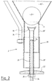
- Figure 2 of the drawing shows an enlarged view the dispensing and metering device 2 as part of the feeding device 1 according to FIG. 1.
- the second, lower valve body 22 which as an arched upward Plate is formed, recognizable.
- the lower valve body 22 is rigid with the tubular actuator 23 connected, welded here.
- the tubular actuator 23 extends through the metering tube 20 up through.
- the second lower valve body 22 and the actuator 23 are as a unit on the vertical guide 24, which is designed here as a threaded rod, in the vertical direction slidably guided.
- the vertical guide 24 is designed here as a threaded rod, in the vertical direction slidably guided.
- the upper end of the actuator 23 is for adjustment to the surface shape of the ball first valve body 21 with a concave curve, so that always a safe and centered system of the actuating element 23 on the first valve body 21 when it is raised by the actuating element 23 is guaranteed.
- the effective length of the actuator 23 is to be chosen so that it is maximal corresponds to the length of the metering tube 20. In this way it is ensured that the transfer of the first Only then valve body 21 in its open position takes place when the second, lower valve body 22 is its Sealing position at the lower end of the metering tube 20 already has reached.
Landscapes
- Life Sciences & Earth Sciences (AREA)
- Environmental Sciences (AREA)
- Birds (AREA)
- Animal Husbandry (AREA)
- Biodiversity & Conservation Biology (AREA)
- Feeding And Watering For Cattle Raising And Animal Husbandry (AREA)
Applications Claiming Priority (2)
| Application Number | Priority Date | Filing Date | Title |
|---|---|---|---|
| DE19739346 | 1997-09-09 | ||
| DE19739346A DE19739346C1 (de) | 1997-09-09 | 1997-09-09 | Fütterungsvorrichtung für Tiere, insbesondere Schweine |
Publications (1)
| Publication Number | Publication Date |
|---|---|
| EP0901751A1 true EP0901751A1 (fr) | 1999-03-17 |
Family
ID=7841630
Family Applications (1)
| Application Number | Title | Priority Date | Filing Date |
|---|---|---|---|
| EP98116795A Withdrawn EP0901751A1 (fr) | 1997-09-09 | 1998-09-05 | Mangeoire pour animaux, en particulier pour des porcs |
Country Status (2)
| Country | Link |
|---|---|
| EP (1) | EP0901751A1 (fr) |
| DE (1) | DE19739346C1 (fr) |
Cited By (1)
| Publication number | Priority date | Publication date | Assignee | Title |
|---|---|---|---|---|
| CN107950414A (zh) * | 2017-12-13 | 2018-04-24 | 贵州黄平勤坡福泰综合养殖有限公司 | 一种养羊自动饲料装置 |
Citations (4)
| Publication number | Priority date | Publication date | Assignee | Title |
|---|---|---|---|---|
| US3834593A (en) * | 1973-06-18 | 1974-09-10 | E James | Adjustable granular material dispenser |
| DD223621A1 (de) * | 1984-05-30 | 1985-06-19 | Fz Fuer Tierproduktion | Selbstfuetterungseinrichtung zur portionsweisen verabreichung fliessfaehiger futtermischungen |
| EP0293520A1 (fr) * | 1987-06-04 | 1988-12-07 | Farco B.V. | Appareil pour le dosage du fourrage |
| EP0815725A1 (fr) * | 1996-07-03 | 1998-01-07 | Jacobus Adrianus Johannus Clemens Nooren | Dispositif pour distribuer des aliments |
Family Cites Families (2)
| Publication number | Priority date | Publication date | Assignee | Title |
|---|---|---|---|---|
| DE2750163A1 (de) * | 1977-11-09 | 1979-05-10 | Erich Decker | Einrichtung zur fuetterung von tieren |
| NL8900054A (nl) * | 1989-01-10 | 1990-08-01 | Kunststoffenbedrijf Azer B V | Door het vee bedienbare veevoedervoorraadbak. |
-
1997
- 1997-09-09 DE DE19739346A patent/DE19739346C1/de not_active Expired - Fee Related
-
1998
- 1998-09-05 EP EP98116795A patent/EP0901751A1/fr not_active Withdrawn
Patent Citations (4)
| Publication number | Priority date | Publication date | Assignee | Title |
|---|---|---|---|---|
| US3834593A (en) * | 1973-06-18 | 1974-09-10 | E James | Adjustable granular material dispenser |
| DD223621A1 (de) * | 1984-05-30 | 1985-06-19 | Fz Fuer Tierproduktion | Selbstfuetterungseinrichtung zur portionsweisen verabreichung fliessfaehiger futtermischungen |
| EP0293520A1 (fr) * | 1987-06-04 | 1988-12-07 | Farco B.V. | Appareil pour le dosage du fourrage |
| EP0815725A1 (fr) * | 1996-07-03 | 1998-01-07 | Jacobus Adrianus Johannus Clemens Nooren | Dispositif pour distribuer des aliments |
Cited By (1)
| Publication number | Priority date | Publication date | Assignee | Title |
|---|---|---|---|---|
| CN107950414A (zh) * | 2017-12-13 | 2018-04-24 | 贵州黄平勤坡福泰综合养殖有限公司 | 一种养羊自动饲料装置 |
Also Published As
| Publication number | Publication date |
|---|---|
| DE19739346C1 (de) | 1998-10-22 |
Similar Documents
| Publication | Publication Date | Title |
|---|---|---|
| DE2336605C2 (de) | Wasserautomat für Geflügel | |
| DE60102921T2 (de) | Selbsttättige fütterungsvorrichtung | |
| DE69802697T2 (de) | Fütterungsvorrichtung für tiere | |
| DE69527647T2 (de) | Fütterungseinrichtung, insbesondere für schweine | |
| DE2438796C2 (de) | Vorrichtung zum portionsweisen Abfüllen von flüssigem oder pastösem Füllgut in Behältnisse | |
| CH644654A5 (de) | Vorrichtung zum zufuehren eines zugabemittels in spuelwassersysteme. | |
| EP0901751A1 (fr) | Mangeoire pour animaux, en particulier pour des porcs | |
| EP0856252A2 (fr) | Procédé et dispositif pour faire fonctionner un appareil mangeoire sensiblement automatique | |
| DE3805149C1 (en) | Arrangement for charging feed places or troughs | |
| EP2242355A1 (fr) | Système d'affouragement automatique, en particulier pour chevaux | |
| DE19754087C2 (de) | Fütterungsgerät | |
| DD223621A1 (de) | Selbstfuetterungseinrichtung zur portionsweisen verabreichung fliessfaehiger futtermischungen | |
| DE2913511A1 (de) | Von tieren, insbesondere wild, zu betaetigende vorrichtung zur dosierten freigabe von rieselfaehigem futter aus einem vorratsbehaelter | |
| DE10302916B3 (de) | Hubdosier-Fütterungsanlage und Verfahren zur Steuerung hierzu | |
| EP0399305B1 (fr) | Appareil pour l'approvisionnement de plusieurs animaux avec nourriture et eau | |
| DE3012047C2 (de) | Dosiereinrichtung zum Fördern von flüssigem Metall | |
| CH667567A5 (de) | Fuetterungsvorrichtung fuer schweine. | |
| DE2442455C2 (de) | Vorrichtung zum Zuführen von pumpfähigen Futterstoffen | |
| DE1632979A1 (de) | Fuetterungsvorrichtung,insbesondere fuer Schweine | |
| CH647648A5 (en) | Device for supplying drinking water for animals | |
| DE2361779C2 (de) | Anlage zum Zuführen dosierter Futtermengen | |
| DE1965703C3 (de) | Automatisch arbeitende Vorrichtung zur Zuteilung von Futter für Schweine | |
| DE19621862A1 (de) | Vorrichtung zur Handhabung von Materialien | |
| DE3105803A1 (de) | Dosiergeraet | |
| AT209105B (de) | Fütterungsanlage für Bienen |
Legal Events
| Date | Code | Title | Description |
|---|---|---|---|
| PUAI | Public reference made under article 153(3) epc to a published international application that has entered the european phase |
Free format text: ORIGINAL CODE: 0009012 |
|
| AK | Designated contracting states |
Kind code of ref document: A1 Designated state(s): DE DK FR NL |
|
| AX | Request for extension of the european patent |
Free format text: AL;LT;LV;MK;RO;SI |
|
| 17P | Request for examination filed |
Effective date: 19990909 |
|
| AKX | Designation fees paid |
Free format text: DE DK FR NL |
|
| 17Q | First examination report despatched |
Effective date: 20010319 |
|
| STAA | Information on the status of an ep patent application or granted ep patent |
Free format text: STATUS: THE APPLICATION IS DEEMED TO BE WITHDRAWN |
|
| 18D | Application deemed to be withdrawn |
Effective date: 20020403 |