EP0901764B1 - Parc d'enfant pliable - Google Patents
Parc d'enfant pliable Download PDFInfo
- Publication number
- EP0901764B1 EP0901764B1 EP98103196A EP98103196A EP0901764B1 EP 0901764 B1 EP0901764 B1 EP 0901764B1 EP 98103196 A EP98103196 A EP 98103196A EP 98103196 A EP98103196 A EP 98103196A EP 0901764 B1 EP0901764 B1 EP 0901764B1
- Authority
- EP
- European Patent Office
- Prior art keywords
- distal end
- tubes
- pivotally connected
- long
- connector
- Prior art date
- Legal status (The legal status is an assumption and is not a legal conclusion. Google has not performed a legal analysis and makes no representation as to the accuracy of the status listed.)
- Expired - Lifetime
Links
- 238000010276 construction Methods 0.000 description 3
- 230000004048 modification Effects 0.000 description 1
- 238000012986 modification Methods 0.000 description 1
- 239000002023 wood Substances 0.000 description 1
Images



Classifications
-
- A—HUMAN NECESSITIES
- A47—FURNITURE; DOMESTIC ARTICLES OR APPLIANCES; COFFEE MILLS; SPICE MILLS; SUCTION CLEANERS IN GENERAL
- A47D—FURNITURE SPECIALLY ADAPTED FOR CHILDREN
- A47D13/00—Other nursery furniture
- A47D13/06—Children's play- pens
- A47D13/061—Children's play- pens foldable
- A47D13/063—Children's play- pens foldable with soft walls
Definitions
- the present invention generally relates to a foldable playyard, and more particularly to a lower frame of a foldable playyard.
- the lower frame of the foldable playyard comprises four long tubes, four short tubes a first distal end of which is pivotally connected with a periphery of one of the long tubes via a first connector, a second distal end of which is pivotally connected with the second distal end of one of the short tubes via a second connector and two intermediate tubes a first distal end of which is pivotally connected with the first distal end of the other intermediate tube via a third connector and a second distal end of which is pivotally connected with two pivotally second distal ends of two short tubes via the second connector.
- the first connector, the second connector and the third connector are configured to allow the first distal ends of the short tube, and the second distal ends of the short tubes and the intermediate tubes to pivot within a range of 90°. Furthermore, an arcuate slot is defined in a periphery of a first distal end of the long tubes thereby allowing each of the long tubes to be rotated when the playyard is unfolded.
- a travelling bed for children with the features corresponding to the preamble of claim 1 is known from DE 195 20 611 C1.
- the main objective of the invention is to provide a substantially rectangular lower frame of a foldable playyard.
- the lower frame of the playyard enables a lower part of the playyard to be folded easily and thus minimize its space for storage.
- Another objective of the invention is to provide a lower frame for a playyard, wherein an arcuate slot is defined in a periphery of the tubes to allow the tubes to be rotated when the lower part of the playyard is about to be folded/unfolded.
- a foldable playyard comprising an upper frame and a lower frame securely connected with said upper frame via poles, in which said lower frame has a rectangular shape and a rotation thereof allows said lower frame to be folded toward said upper frame;
- said lower frame comprises four long tubes, four short tubes each having a first distal end which is pivotally connected with a periphery of a respective one of said long tubes via one of four first connectors and a second distal end of which is pivotally connected with said second distal end of another one of said short tubes via one of two second connectors, and two intermediate tubes each having a first distal end which is pivotally connected with said first distal end of the other intermediate tube via a third connector and a second distal end which is pivotally connected with two second distal ends of two short tubes via said second connector; a first distal end of each long tube being pivotally connected with said first distal end of another long tube via a fourth connector and a second distal end of each said long tube being pivotally connected with a respective one of four stands
- a foldable playyard constructed in accordance with the present invention is shown.
- the foldable playyard has an upper frame 10 and a lower frame 20. Because a detailed description of the upper frame 10 has been disclosed in the pending application Serial No.08/787,446 (US-A-5 781 944), a structure and operation of the upper frame 10 is thus omitted.
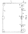
- the lower frame 20 of the foldable playyard includes four long tubes 21, four short tubes 22, two intermediate tubes 23, four first connectors 30, two second connectors 40, one third connector 50 and two fourth connectors 60.
- the short tubes 22 are separated into two aligned pairs.
- the long tubes 21 are separated into two aligned pairs.
- a first distal end 211 of each long tube 21 is pivotally connected by means of one of the fourth connectors 60 to the first distal end 211 of the other long tube 21 to which it is paired.
- a second distal end 212 of each long tube 21 is pivotally received in a respective one of four corner stands 70.
- a distal end 221 of each short tube 22 is pivotally connected to a respective one of the long tubes 21 by a respective one of the first connectors 30.
- a second distal end 222 of each short tube is pivotally connected by means of one of the second connectors 40 to the second distal end 222 of the other short tube 22 to which it is paired.
- the intermediate tubes 23 are arranged as an aligned pair.
- a first distal end 231 of one of the intermediate tubes 23 is pivotally connected to the corresponding first end 231 of the other intermediate tube 23.
- a second end 232 of each intermediate tube 23 is pivotally connected by means of a respective one of the second connectors 40 to a corresponding aligned pair of second tubes 23.
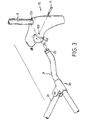
- Each long tube 21 has defined in a periphery thereof an arcuate slot 213 into which a pin 71 is slidably received.
- the first connector 30, the second connector 40, the third connector 50 and the forth connector 60 are so configured that the first distal ends 221 and second distal ends 222 of the short tubes 22, the first distal end 211 and second distal end 212 of the long tube 21 and the first distal end 231 and the second distal end 232 of the intermediate tubes 23 can only pivot within a range of 90° toward the upper frame 10 when the lower frame 20 is being folded (as shown in Fig. 4A).
- the stand 70 is configured to have a first cavity 701 and a second cavity 702 to respectively receive a pole 11 of the upper frame 10 and the respective second distal end 212 of the long tube 21 therein.
- a through hole 703 is defined in a periphery of the stand 70, such that the second distal end 212 of the long tube 21 is able to pivot within the second space 702 when the pin 71 is inserted into the through hole 703 and then the second distal end 212 of the long tube 21.
- the pin 71 when the pin 71 is inserted into the second distal end 212 of the long tube 21, the pin 71 is disposed within the arcuate slot 213, therefore, the long tube 21 is thus able to rotate for a certain angle by the movement of the pin 71 within the arcuate slot 213.
- FIGs 4 and 4A show the folding of the short tubes 22 toward the upper frame 10 whereby the long tubes 21 rotate for a certain degree. It is understood that when the short tubes 22 are folded upward and toward the upper frame 10, due to the pivotal connection between each first connector 30 and the respective first distal end 221 of the short tube 22 and the secured connection between each first connector 30 and the periphery of the respective long tube 21, the long tubes 21 will somewhat be lifted upward and a rotation thereof is inevitable.
- each arcuate slot 213 defined in the second distal end 212 of the respective long tube 21 allows the rotation thereof to be possible, which permits the aligned pairs of long tubes 21 to be folded with the folding movement of the short tubes 22.
- Figure 3 shows that a length of the arcuate slot 213 is formed to limit the rotation of the long tubes 21 to be in a range of 90°, by which is possible to allow the long tubes 21 to rotate within this range.
- the foldable playyard constructed in accordance with the present invention is able to be folded into the form as shown, such that the playyard is readily convenient for storage and transporting.
Landscapes
- Toys (AREA)
- Tents Or Canopies (AREA)
- Carriages For Children, Sleds, And Other Hand-Operated Vehicles (AREA)
Claims (3)
- Parc pliable comprenant un cadre supérieur (10) et un cadre inférieur (20) solidement connecté audit cadre supérieur au moyen de tiges (11), ledit cadre inférieur ayant une forme rectangulaire et une rotation de celui-ci permettant audit cadre inférieur (20) d'être replié vers ledit cadre supérieur (10) ;
dans lequel ledit cadre inférieur (20) comprend quatre tubes longs (21), quatre tubes courts (22) ayant chacun une première extrémité distale qui est connectée à pivotement avec une périphérie d'un tube respectif parmi lesdits tubes longs (21) au moyen d'un connecteur parmi quatre premiers connecteurs (30) et une deuxième extrémité distale qui est connectée à pivotement avec ladite deuxième extrémité distale d'un autre desdits tubes courts (22) au moyen d'un connecteur parmi deux deuxièmes connecteurs (40), et deux tubes intermédiaires (23) ayant chacun une première extrémité distale qui est connectée à pivotement avec ladite première extrémité distale de l'autre tube intermédiaire au moyen d'un troisième connecteur (50) et une deuxième extrémité distale qui est connectée à pivotement avec deux deuxièmes extrémités distales de deux tubes courts au moyen dudit deuxième connecteur (40) ;
une première extrémité distale de chaque tube long (21) étant connectée à pivotement avec ladite première extrémité distale d'un autre tube long (21) au moyen d'un quatrième connecteur (60) et une deuxième extrémité distale de chacun desdits tubes longs (21) étant connectée à pivotement avec un pied respectif parmi quatre pieds (70) qui reçoivent chacun solidement à l'intérieur une tige correspondante parmi lesdites tiges (11) dudit cadre supérieur (10) ;
caractérisé en ce que
une fente arquée (213) est définie dans une périphérie de ladite deuxième extrémité distale de chacun desdits tubes longs (21), permettant à ladite deuxième extrémité distale de chacun desdits tubes longs (21) d'être reçue à rotation dans un pied respectif parmi lesdits pieds (70). - Parc pliable selon la revendication 1, dans lequel un axe parmi quatre axes (71) est inséré à travers un pied respectif parmi lesdits pieds (70) et ladite fente arquée (213) de ladite deuxième extrémité distale de chacun desdits tubes longs (21) permettant audit tube long (21) de tourner sur une longueur de ladite fente arquée (213).
- Parc pliable selon la revendication 2, dans lequel une longueur de chacune desdites fentes arquées (213) est définie pour limiter la rotation dudit tube long (21) à l'intérieur d'une plage de 90°.
Applications Claiming Priority (2)
| Application Number | Priority Date | Filing Date | Title |
|---|---|---|---|
| US99954497A | 1997-09-15 | 1997-09-15 | |
| US999544 | 1997-09-15 |
Publications (3)
| Publication Number | Publication Date |
|---|---|
| EP0901764A2 EP0901764A2 (fr) | 1999-03-17 |
| EP0901764A3 EP0901764A3 (fr) | 2000-04-19 |
| EP0901764B1 true EP0901764B1 (fr) | 2005-05-11 |
Family
ID=25546463
Family Applications (1)
| Application Number | Title | Priority Date | Filing Date |
|---|---|---|---|
| EP98103196A Expired - Lifetime EP0901764B1 (fr) | 1997-09-15 | 1998-02-24 | Parc d'enfant pliable |
Country Status (4)
| Country | Link |
|---|---|
| EP (1) | EP0901764B1 (fr) |
| AT (1) | ATE295103T1 (fr) |
| CA (1) | CA2232538A1 (fr) |
| DE (1) | DE69830112D1 (fr) |
Cited By (1)
| Publication number | Priority date | Publication date | Assignee | Title |
|---|---|---|---|---|
| WO2008043252A1 (fr) * | 2006-09-18 | 2008-04-17 | Kika Commodity Design Service Department | Lit musical enveloppant pliable |
Family Cites Families (3)
| Publication number | Priority date | Publication date | Assignee | Title |
|---|---|---|---|---|
| US3110913A (en) * | 1962-01-05 | 1963-11-19 | Henry J Landry | Folding play yard center leg |
| DE19520611C1 (de) * | 1995-06-06 | 1997-01-23 | Hauck Gmbh & Co Kg | Zusammenklappbares Reisebett, insbesondere Kinderreisebett, oder dergleichen |
| DE29513579U1 (de) * | 1995-08-24 | 1995-11-09 | Jina Manufacturer Thai Co., Ltd., Bangkok | Zusammenlegbarer Laufstallboden |
-
1998
- 1998-02-24 DE DE69830112T patent/DE69830112D1/de not_active Expired - Lifetime
- 1998-02-24 EP EP98103196A patent/EP0901764B1/fr not_active Expired - Lifetime
- 1998-02-24 AT AT98103196T patent/ATE295103T1/de not_active IP Right Cessation
- 1998-03-18 CA CA002232538A patent/CA2232538A1/fr not_active Abandoned
Cited By (1)
| Publication number | Priority date | Publication date | Assignee | Title |
|---|---|---|---|---|
| WO2008043252A1 (fr) * | 2006-09-18 | 2008-04-17 | Kika Commodity Design Service Department | Lit musical enveloppant pliable |
Also Published As
| Publication number | Publication date |
|---|---|
| CA2232538A1 (fr) | 1999-03-15 |
| ATE295103T1 (de) | 2005-05-15 |
| DE69830112D1 (de) | 2005-06-16 |
| EP0901764A2 (fr) | 1999-03-17 |
| EP0901764A3 (fr) | 2000-04-19 |
Similar Documents
| Publication | Publication Date | Title |
|---|---|---|
| EP1082927B1 (fr) | Parc pliant avec dispositif de sécurité | |
| US12221146B2 (en) | Foldable wagon | |
| US6026751A (en) | Collapsible table | |
| US7591031B2 (en) | Control device of lower frame assembly for a playpen | |
| US6048062A (en) | Structure of foldable glasses | |
| EP4710817A1 (fr) | Panier de couchage pliable pour bébé | |
| CN110652138A (zh) | 一种折叠床 | |
| WO2022258803A1 (fr) | Mécanisme de pliage de cadre et cadre de lit de bébé | |
| EP0901764B1 (fr) | Parc d'enfant pliable | |
| US6263525B1 (en) | Foldable frame of a playpen | |
| EP0972473B1 (fr) | Articulation verrouillable pour lit de bébé | |
| US7600276B2 (en) | Baby crib including a top frame unit that can be disassembled | |
| US6767027B2 (en) | Folding structure for basket support of a stroller | |
| US6499906B1 (en) | Pivot joint foldable furniture | |
| CN217695576U (zh) | 一种折叠桌腿的结构 | |
| EP0366626A1 (fr) | Niche portable et pliante pour animaux domestiques | |
| CN108420224B (zh) | 折叠床 | |
| GB2218625A (en) | Collapsible table | |
| CA2122549A1 (fr) | Parc pour petits enfants | |
| KR200221306Y1 (ko) | 절첩식 상품 진열대 | |
| CN213820716U (zh) | 一种运用于折叠儿童床架的折叠装置 | |
| JPH10101066A (ja) | 組立式コンテナ | |
| CN224099214U (zh) | 一种便于运输的儿童浴盆 | |
| CN219456701U (zh) | 便于使用的折叠式柔光箱 | |
| CN218099898U (zh) | 柔光板的旗板框及柔光板 |
Legal Events
| Date | Code | Title | Description |
|---|---|---|---|
| PUAI | Public reference made under article 153(3) epc to a published international application that has entered the european phase |
Free format text: ORIGINAL CODE: 0009012 |
|
| 17P | Request for examination filed |
Effective date: 19980224 |
|
| AK | Designated contracting states |
Kind code of ref document: A2 Designated state(s): AT BE CH DE DK ES FI FR GB GR IE IT LI LU MC NL PT SE |
|
| AX | Request for extension of the european patent |
Free format text: AL;LT PAYMENT 980224;LV;MK;RO;SI PAYMENT 980224 |
|
| PUAL | Search report despatched |
Free format text: ORIGINAL CODE: 0009013 |
|
| AK | Designated contracting states |
Kind code of ref document: A3 Designated state(s): AT BE CH DE DK ES FI FR GB GR IE IT LI LU MC NL PT SE |
|
| AX | Request for extension of the european patent |
Free format text: AL;LT PAYMENT 19980224;LV;MK;RO;SI PAYMENT 19980224 |
|
| AKX | Designation fees paid |
Free format text: AT BE CH DE DK ES FI FR GB GR IE IT LI LU MC NL PT SE |
|
| AXX | Extension fees paid |
Free format text: LT PAYMENT 19980224;SI PAYMENT 19980224 |
|
| 17Q | First examination report despatched |
Effective date: 20010725 |
|
| GRAG | Despatch of communication of intention to grant |
Free format text: ORIGINAL CODE: EPIDOS AGRA |
|
| GRAG | Despatch of communication of intention to grant |
Free format text: ORIGINAL CODE: EPIDOS AGRA |
|
| GRAH | Despatch of communication of intention to grant a patent |
Free format text: ORIGINAL CODE: EPIDOS IGRA |
|
| GRAH | Despatch of communication of intention to grant a patent |
Free format text: ORIGINAL CODE: EPIDOS IGRA |
|
| GRAA | (expected) grant |
Free format text: ORIGINAL CODE: 0009210 |
|
| AK | Designated contracting states |
Kind code of ref document: B1 Designated state(s): AT BE CH DE DK ES FI FR GB GR IE IT LI LU MC NL PT SE |
|
| AX | Request for extension of the european patent |
Extension state: LT SI |
|
| PG25 | Lapsed in a contracting state [announced via postgrant information from national office to epo] |
Ref country code: NL Free format text: LAPSE BECAUSE OF FAILURE TO SUBMIT A TRANSLATION OF THE DESCRIPTION OR TO PAY THE FEE WITHIN THE PRESCRIBED TIME-LIMIT Effective date: 20050511 Ref country code: LI Free format text: LAPSE BECAUSE OF FAILURE TO SUBMIT A TRANSLATION OF THE DESCRIPTION OR TO PAY THE FEE WITHIN THE PRESCRIBED TIME-LIMIT Effective date: 20050511 Ref country code: IT Free format text: LAPSE BECAUSE OF FAILURE TO SUBMIT A TRANSLATION OF THE DESCRIPTION OR TO PAY THE FEE WITHIN THE PRESCRIBED TIME-LIMIT;WARNING: LAPSES OF ITALIAN PATENTS WITH EFFECTIVE DATE BEFORE 2007 MAY HAVE OCCURRED AT ANY TIME BEFORE 2007. THE CORRECT EFFECTIVE DATE MAY BE DIFFERENT FROM THE ONE RECORDED. Effective date: 20050511 Ref country code: FI Free format text: LAPSE BECAUSE OF FAILURE TO SUBMIT A TRANSLATION OF THE DESCRIPTION OR TO PAY THE FEE WITHIN THE PRESCRIBED TIME-LIMIT Effective date: 20050511 Ref country code: CH Free format text: LAPSE BECAUSE OF FAILURE TO SUBMIT A TRANSLATION OF THE DESCRIPTION OR TO PAY THE FEE WITHIN THE PRESCRIBED TIME-LIMIT Effective date: 20050511 Ref country code: BE Free format text: LAPSE BECAUSE OF FAILURE TO SUBMIT A TRANSLATION OF THE DESCRIPTION OR TO PAY THE FEE WITHIN THE PRESCRIBED TIME-LIMIT Effective date: 20050511 Ref country code: AT Free format text: LAPSE BECAUSE OF FAILURE TO SUBMIT A TRANSLATION OF THE DESCRIPTION OR TO PAY THE FEE WITHIN THE PRESCRIBED TIME-LIMIT Effective date: 20050511 |
|
| REG | Reference to a national code |
Ref country code: GB Ref legal event code: FG4D |
|
| REG | Reference to a national code |
Ref country code: CH Ref legal event code: EP |
|
| REG | Reference to a national code |
Ref country code: IE Ref legal event code: FG4D |
|
| REF | Corresponds to: |
Ref document number: 69830112 Country of ref document: DE Date of ref document: 20050616 Kind code of ref document: P |
|
| PG25 | Lapsed in a contracting state [announced via postgrant information from national office to epo] |
Ref country code: SE Free format text: LAPSE BECAUSE OF FAILURE TO SUBMIT A TRANSLATION OF THE DESCRIPTION OR TO PAY THE FEE WITHIN THE PRESCRIBED TIME-LIMIT Effective date: 20050811 Ref country code: GR Free format text: LAPSE BECAUSE OF FAILURE TO SUBMIT A TRANSLATION OF THE DESCRIPTION OR TO PAY THE FEE WITHIN THE PRESCRIBED TIME-LIMIT Effective date: 20050811 Ref country code: DK Free format text: LAPSE BECAUSE OF FAILURE TO SUBMIT A TRANSLATION OF THE DESCRIPTION OR TO PAY THE FEE WITHIN THE PRESCRIBED TIME-LIMIT Effective date: 20050811 |
|
| PG25 | Lapsed in a contracting state [announced via postgrant information from national office to epo] |
Ref country code: DE Free format text: LAPSE BECAUSE OF FAILURE TO SUBMIT A TRANSLATION OF THE DESCRIPTION OR TO PAY THE FEE WITHIN THE PRESCRIBED TIME-LIMIT Effective date: 20050812 |
|
| PG25 | Lapsed in a contracting state [announced via postgrant information from national office to epo] |
Ref country code: ES Free format text: LAPSE BECAUSE OF FAILURE TO SUBMIT A TRANSLATION OF THE DESCRIPTION OR TO PAY THE FEE WITHIN THE PRESCRIBED TIME-LIMIT Effective date: 20050822 |
|
| PG25 | Lapsed in a contracting state [announced via postgrant information from national office to epo] |
Ref country code: PT Free format text: LAPSE BECAUSE OF FAILURE TO SUBMIT A TRANSLATION OF THE DESCRIPTION OR TO PAY THE FEE WITHIN THE PRESCRIBED TIME-LIMIT Effective date: 20051019 |
|
| LTIE | Lt: invalidation of european patent or patent extension |
Effective date: 20050511 |
|
| NLV1 | Nl: lapsed or annulled due to failure to fulfill the requirements of art. 29p and 29m of the patents act | ||
| REG | Reference to a national code |
Ref country code: CH Ref legal event code: PL |
|
| PG25 | Lapsed in a contracting state [announced via postgrant information from national office to epo] |
Ref country code: IE Free format text: LAPSE BECAUSE OF NON-PAYMENT OF DUE FEES Effective date: 20060224 Ref country code: GB Free format text: LAPSE BECAUSE OF NON-PAYMENT OF DUE FEES Effective date: 20060224 |
|
| REG | Reference to a national code |
Ref country code: FR Ref legal event code: RN |
|
| PG25 | Lapsed in a contracting state [announced via postgrant information from national office to epo] |
Ref country code: MC Free format text: LAPSE BECAUSE OF NON-PAYMENT OF DUE FEES Effective date: 20060228 Ref country code: LU Free format text: LAPSE BECAUSE OF NON-PAYMENT OF DUE FEES Effective date: 20060228 |
|
| PLBE | No opposition filed within time limit |
Free format text: ORIGINAL CODE: 0009261 |
|
| STAA | Information on the status of an ep patent application or granted ep patent |
Free format text: STATUS: NO OPPOSITION FILED WITHIN TIME LIMIT |
|
| REG | Reference to a national code |
Ref country code: FR Ref legal event code: FC |
|
| EN | Fr: translation not filed | ||
| ET | Fr: translation filed | ||
| 26N | No opposition filed |
Effective date: 20060214 |
|
| EN | Fr: translation not filed | ||
| GBPC | Gb: european patent ceased through non-payment of renewal fee |
Effective date: 20060224 |
|
| REG | Reference to a national code |
Ref country code: IE Ref legal event code: MM4A |
|
| PG25 | Lapsed in a contracting state [announced via postgrant information from national office to epo] |
Ref country code: FR Free format text: LAPSE BECAUSE OF FAILURE TO SUBMIT A TRANSLATION OF THE DESCRIPTION OR TO PAY THE FEE WITHIN THE PRESCRIBED TIME-LIMIT Effective date: 20050511 |