EP0901767A1 - Grille-pain à remontée ralentie - Google Patents
Grille-pain à remontée ralentie Download PDFInfo
- Publication number
- EP0901767A1 EP0901767A1 EP98420155A EP98420155A EP0901767A1 EP 0901767 A1 EP0901767 A1 EP 0901767A1 EP 98420155 A EP98420155 A EP 98420155A EP 98420155 A EP98420155 A EP 98420155A EP 0901767 A1 EP0901767 A1 EP 0901767A1
- Authority
- EP
- European Patent Office
- Prior art keywords
- carriage
- bread
- retarder
- toaster
- housing
- Prior art date
- Legal status (The legal status is an assumption and is not a legal conclusion. Google has not performed a legal analysis and makes no representation as to the accuracy of the status listed.)
- Withdrawn
Links
Images



Classifications
-
- A—HUMAN NECESSITIES
- A47—FURNITURE; DOMESTIC ARTICLES OR APPLIANCES; COFFEE MILLS; SPICE MILLS; SUCTION CLEANERS IN GENERAL
- A47J—KITCHEN EQUIPMENT; COFFEE MILLS; SPICE MILLS; APPARATUS FOR MAKING BEVERAGES
- A47J37/00—Baking; Roasting; Grilling; Frying
- A47J37/06—Roasters; Grills; Sandwich grills
- A47J37/08—Bread-toasters
- A47J37/0814—Bread-toasters with automatic bread ejection or timing means
Definitions
- the present application relates to the field of cooking appliances for electric toaster type, and more particularly to an improved device for slower rise of the bread carrier.
- Such a function on a toaster is known, for example from the document FR-2 035 965 where the slowing of the ascent of the bread carrier is obtained by a flywheel, driven in rotation by friction of a wheel secured to the steering wheel, on the carriage guide column.
- This steering wheel is mounted on an articulated arm which is arched against the column, thus creating grip necessary for the rotation of the caster, when raising the carriage. To the lowering, this arm escapes, thus avoiding unnecessary wear of the mechanism as well an untimely effort from the toaster user.
- the energy stored in the carriage return device generally a spring, is transferred to the flywheel which therefore dampens the displacement accelerated from the toaster.
- Such a system has the major drawback of producing movement accelerated flywheel which when the carriage is returned to its position of rest, after toasting the bread, continues to turn, generating an unnecessary noise as well as mechanical stress between the caster and the guide column.
- toasters have a damped lift from the carriage, called “dashpot", either using damping springs, or by sets of cylinder-piston type with air leakage or pinion-rack type. Such systems remain ineffective over the entire travel of the carriage, often little reliable over time and complex.
- the amortization is effective from the start the ascent, which can be dangerous.
- the bread rack trolley serves very often to establish the electrical contact triggering the supply of heating resistors. It is therefore necessary that this carriage can go up over a certain height without being braked, in order to ensure the electrical cut-off of the heating circuit, in case the bread remains, for example, stuck to the surface of the retaining grids.
- One of the objectives of the present invention is to solve these drawbacks of so as to slow down the ascent of the bread carriage silent, of perfectly reproducible characteristic and offering the same safeties that a toaster without such a device.
- Another object of the present invention aims to achieve such a system with simple elements, in order to reduce the cost of such a function.
- a toaster electric comprising a frame provided with a chassis, a slot for introducing the bread, a baking chamber, heating elements arranged in the vicinity of the baking chamber, a mobile bread trolley, inside the cooking chamber, between at least one broiling position and one rest, a guide rod to optimize the movement of the carriage, a means blocking in order to position the carriage at a lower level corresponding to the wire mesh position, a carriage return means mounted on the carriage and on the frame, a system capable of slowing the ascent of the carriage, characterized in that this system is arranged on an extension of the carriage bread holder, outside the toasting chamber and consists of a retarder viscous or friction type rotary, activated when the carriage is released and rises from its grid position to a rest position.
- the retarder consists of a housing formed either only by elements integral with an extension of the bread-carrying trolley, or in part by said elements and by an element capable of being rotated, the viscous or friction type friction occurring inside the housing by an element rotated relative to a fixed element integral with the retarder system housing when the carriage is released and rises from its grill position to a rest position.
- the slowdown is thus protected from the external environment, in particular dust and bread crumbs for example which can block the system, while allowing, according to one of the alternative embodiments, a viscous type friction inside the housing.
- rotary grease retarders commonly called “damper” which are standard components, having a rotatable disc around an axis, in a viscous environment. They are commonly used, especially in precision mechanical engineering, where they serve, for example, to slow down the movement of a piece so as not to rush its fragile environment.
- Such elements can be used to slow the ascent of the toaster carriage of a toaster, taking into account the constraints related to the heat prevailing around the cooking chamber as well as forces recall involved.
- This ascent slowdown system of the bread basket using a grease retarder is linked to the viscosity of the fluid contained in the retarder. This fluid is trapped in a airtight enclosure, or case, so that the bread crumbs, generated during the use of the toaster, cannot disturb the operation of this system.
- One of the embodiments of this system consists in associating a room external to the axis of rotation of the viscous retarder disc, this part being a friction roller capable of being rotated on a vertical element when the carriage is released and rises from its grid position to a rest position.
- This roller allows the rotation of the retarder disc in a viscous environment, to perform the announced slowing function of the raising of the bread basket, and this in a silent way.
- the retarder used is a friction retarder, composed of at least one part capable of being rotation on the vertical element when the carriage is released and rises from its grid position towards a rest position, this rotation being effected by relative to a fixed element of the housing of the retarder system, presenting a coefficient of friction on this element adapted to the desired slowdown.
- This device avoids the use of grease or viscous liquid.
- One of embodiments of this latter configuration is to have a ring as well as a faceted piece, one of the two pieces being integral of the rotating part, while the other is secured to the housing, said facets being in contact with the internal surface of the ring and susceptible to slow down the rotational movement of the part pressing on the vertical element, by friction on this ring when the carriage is released and rises from its position wire mesh to a rest position.
- the vertical element is the guide rod of the bread-carrying carriage, thus reducing the number of parts required to make such a function.
- the external part of the system retarder capable of being rotated, is covered with a material rubbery, to ensure a rolling without sliding of this part on the guide rod and / or to limit noise.
- the external part of the retarder system can be rotated, is made entirely of material rubbery.
- the coating rubbery has a groove-shaped peripheral profile suitable for shape of the guide rod. This configuration allows better coupling between the rod and the rotating part as well as a more reliable guidance of the retarder during different movements.
- the external part of the retarder system capable of being rotated, has a shape of toothed pinion and can be rotated by meshing on a vertical rack, when the carriage is released and rises from its grill position to a rest position.
- the rack can be molded in the outer shell of the toaster in a thermoplastic material.
- the rack is the guide rod of the bread carriage.
- the housing of the retarder has an extension forming an articulated arm on the extension of the bread trolley, this arm being oriented substantially obliquely relative to to the ascent axis of the bread carrier.
- Figure 1 shows an embodiment of the deceleration mechanism Bringing up the bread basket of an electric toaster, in a view in perspective where only the functional elements relating to the present invention.
- a bread carriage (2) arranged on the frame (1) of a toaster having at least one bread insertion slot, a bread carriage (2) can be move, inside a cooking chamber (3) having elements heaters arranged in its vicinity, between a rest position and a low wire position, in which it can be maintained by means of blocking, guided by a piece (4) integral with said carriage which slides on a guide rod (5), outside the cooking chamber.
- a reminder of the carriage, not shown, is mounted on the carriage and on the frame.
- an arm (8a) oriented obliquely to the guide rod of the carriage and articulated around an axis (10) parallel to the bread carriage, allowing it to be mobile rotating around this axis.
- a grease retarder (6) is attached to this arm. whose axis (7a) of its internal disc is linked to a roller (13) which comes into contact of the guide rod (5).
- the roller is rotated by friction on the vertical element (5).
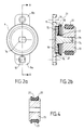
- Figure 2a shows a front view of the retarder (6) used.
- the arm (8a) constitutes a stop to limit the rotational movement of the retarder around the axis (10).
- Figure 2b is a sectional view, along the plane A-A shown in Figure 2a, of that same retarder.
- the arm (8a) is an extension the housing (14) of the retarder (6).
- This chamber is filled with grease (19) or viscous substance.
- the axis (7a) opens from this chamber (16) through an orifice formed in the cover (18). The rotation of this axis (7a) allows to train the disc (15) rotating in the grease.
- the axis (7a) and the disc (15) form only one piece.
- a roller (13) is fixedly attached to the axis (7a), however either, so that a rotation of the roller (13) causes a rotation of the axis (7a), therefore of the disc (15).
- One of the possible methods of fixing the two parts is a male / female type adjustment according to a non-circular section, as shown in Figure 2a where the axis section (7a) is shaped generally rectangular and corresponds to a complementary recess (7b) formed in the roller (13).
- the rotation of the roller, by rolling on the rod guide (5) of the bread holder carriage therefore causes a viscous type friction of the disc (15) in the grease (19).
- the roller (13) is covered with a rubber band (20) in order to ensure a rolling without sliding of the roller (13) on the rod guide (5) of the bread carriage.
- the roller (13) is made entirely of rubbery material, which avoids the friction band (20).
- This rubber band (20) can constitute a noise-absorbing tape caused by the device during use a rack drive method, as described later in Requirement.
- Figure 3 illustrates the operating principle of the system retarder. This figure represents the retarder (6) in its slowdown operation when raising the bread basket.
- FIG. 3 shows that this device is not active during the descent of the carriage.
- Figure 4 provides a sectional view along the plane A-A of Figure 2a of roller (13) equipped with a variant of the shape of the rubber coating (20).
- This coating has a groove (21) which can come into contact with the rod. guide (5) to thereby increase the contact surface, which makes the more reliable deceleration system.
- the main feature of this first version of the slowing of the rise of the bread basket is linked to the viscosity of the fluid contained in the housing (14) of the retarder. This fluid being trapped in a sealed enclosure, the bread crumbs, generated during repeated use of the toaster, cannot interfere with operation of this system.
- the system retarder is only active after a few millimeters of carriage travel, corresponding to the inertia of the device, to the dynamics of the process, as well as to the arm rotation (8a).
- This non-slowed down stroke is of sufficient amplitude to ensure the loosening of the bread from the holding grids and to cut the electrical supply of the heating means.
- Figure 5a is a longitudinal section view along plane B-B of FIG. 5b of the retarder at friction
- Figure 5b is a cross-sectional view along the plane A-A of FIG. 5a of this same retarder.
- This includes a housing (14) as well as a cylindrical axis (7a), integral with one face (11) of the housing (14) of the retarder, free of grease.
- the axis (7a) and the face (11) form only one element.
- the roller (13) is mounted with a slight play on the axis (7a), so that it can rotate freely around this axis.
- the axis (7a) has a stop zone (24) at its end, under the shape, for example of a stop. Furthermore, an elastomer ring (22), characterized by a determined coefficient of friction, is made integral with the part (11) of the housing (14) of the retarder, for example, by overmolding. So, the housing (14) is constituted by the part (11), the ring (22) and by the roller (13).
- the roller (13) extends, through its barrel, inside the ring (22) in having, peripherally, molded facets (23), the dimensions are such that they exert a determined contact pressure on the inner surface of the ring (22).
- the roller (13) is covered with a rubber coating (20). So when this coating (20) comes into friction with the guide rod (5), when ascent of the bread-carrying carriage, the roller (13) is rotated around the axis (7a), its facets (23) then rub against the internal surface of the ring (22), inside the housing (14), thus creating the slowing of the carriage recovery.
- FIGS. 5a and 5b show, on the same principle slowing the ascent of the carriage, another embodiment of the friction retarder, according to the same sectional views as in FIGS. 5a and 5b.
- the roller (13) is made of elastomer and comprises the ring (22).
- the axis (7a), connected to the part (11) of the housing (14), comprises the friction facets (23).
- the housing is always formed by the part (11), the ring (22) and the roller (13), but with respect to FIGS. 5a and 5b, these are not not the same parts that are set in motion.
- the friction phenomenon is, according to this configuration, accentuated by the deformation of the elastomeric roller.
- the shape of the facets (23) such as presented in FIG. 5a or 6a is not limiting, and it is possible to present any other shape allowing different contact surfaces to be obtained the ring (22), in order to adapt the device to the desired slowdown, without depart from the scope of the present invention.
- the part likely to be rotated when raising the bread carrier that is to say the roller (13)
- the roller (13) has a shape of pinion.
- the toaster has a vertical element having a rack shape adapted to the teeth roller (13).
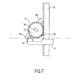
- FIG. 7 shows such a device applied to a retarder at fat.
- the grease retarder system (6) in operation, when raising the bread basket.
- the particularity of this variant therefore resides in the roller (13) which has the shape of a pinion, obtained for example by molding.
- a rack (26) adapted by its pitch to the serrated shape (25) of the roller (13) is arranged vertically inside the toaster.
- a coating may be provided.
- elastomer on this pinion in order to limit the noise linked to the meshing of this element on the rack.
- a thinning of the rack at its base can be done, in order to make inactive the slowing device on the first centimeters of ascent of the carriage.
- This rack (26) can be molded in the outer casing of the toaster, or, advantageously, it can be the guide rod of the carriage bread.
- the present invention economically solves the function of slowing of the ascent of the bread basket using an element standard, with adjusted characteristics. This significantly reduces the cost price of a toaster equipped with such a function.
Landscapes
- Engineering & Computer Science (AREA)
- Food Science & Technology (AREA)
- Vibration Prevention Devices (AREA)
Abstract
Description
- la figure 1 est une vue en perspective du mécanisme de remontée ralentie monté sur le châssis du grille-pain, le chariot étant en position de repos,
- les figures 2a et 2b représentent le ralentisseur à graisse équipé du galet de friction, respectivement en vue de face et en vue selon la coupe A-A,
- la figure 3 représente un schéma simplifié du principe de fonctionnement du dispositif ralentisseur,
- la figure 4 est une variante de construction du galet associé au ralentisseur,
- les figures 5a, 5b, 6a et 6b représentent deux variantes de construction du ralentisseur à friction.
- la figure 7 représente une variante de construction du dispositif de ralentissement.
Claims (13)
- Grille-pain électrique, comportant un bâti pourvu d'un châssis (1), une fente d'introduction du pain, une chambre de cuisson (3), des éléments chauffants agencés au voisinage de la chambre de cuisson, un chariot porte pain (2) mobile, à l'intérieur de la chambre de cuisson, entre au moins une position de grillage et une position de repos, une tige de guidage (5) pour optimiser le déplacement du chariot, un moyen de blocage afin de positionner le chariot à un niveau inférieur correspondant à la position de grillage, un moyen de rappel du chariot monté sur le chariot et sur le bâti, un système susceptible de ralentir la remontée du chariot, caractérisé en ce que ce système est disposé sur une extension (4) du chariot porte pain, hors de la chambre de grillage et est constitué d'un ralentisseur (6) rotatif de type visqueux ou de type friction, activé lorsque le chariot est libéré et remonte de sa position de grillage vers une position de repos.
- Grille-pain selon la revendication 1, caractérisé en ce que le ralentisseur (6) est constitué d'un boítier (14) formé soit uniquement par des éléments solidaires d'une extension du chariot porte pain, soit en partie par lesdits éléments et par un élément susceptible d'être mis en rotation, le frottement de type visqueux ou de type friction se réalisant à l'intérieur du boítier (14) par un élément (13) mis en rotation par rapport à un élément fixe solidaire du boítier (14) du système ralentisseur (6) lorsque le chariot est libéré et remonte de sa position de grillage vers une position de repos.
- Grille-pain selon l'une des revendications précédentes, caractérisé en ce que le ralentisseur (6) est de type visqueux, constitué d'un disque (15) d'axe de rotation (7a), comportant un galet de friction (13) situé à l'extérieur du boítier (14), associé à l'axe de rotation (7a) du disque (15) du ralentisseur (6), ce galet (13) étant mis en rotation sur un élément vertical lorsque le chariot est libéré et remonte de sa position de grillage vers une position de repos.
- Grille-pain selon la revendication 3, caractérisé en ce que le ralentisseur (6) comporte :l'un des deux éléments (22, 23) étant solidaire de l'élément (13), tandis que l'autre est solidaire du boítier (14), lesdites facettes de la pièce (23) étant en contact avec la surface interne de l'anneau (22) et susceptibles de ralentir le mouvement de rotation de l'élément (13) par friction sur cet anneau (22) lorsque le chariot est libéré et remonte de sa position de grillage vers une position de repos.un anneau (22)une pièce à facettes (23),
- Grille-pain selon l'une des revendications précédentes, caractérisé en ce que l'élément vertical est la tige de guidage (5) du chariot porte-pain.
- Grille-pain selon l'une des revendications précédentes, caractérisé en ce que l'élément (13), susceptible d'être mis en rotation, est recouvert d'une matière caoutchouteuse (20).
- Grille-pain selon l'une des revendications précédentes, caractérisé en ce que l'élément (13) est entièrement constituée de matière caoutchouteuse.
- Grille-pain selon l'une des revendications précédentes, caractérisé en ce que l'élément (13) présente un profil périphérique en forme de gorge adaptée à la forme de la tige de guidage.
- Grille-pain selon l'une des revendications 1 à 7, caractérisé en ce que l'élément (13) présente une forme de pignon à dents (25) et est susceptible d'être mis en rotation par engrènement sur une crémaillère (26) verticale, lorsque le chariot est libéré et remonte de sa position de grillage vers une position de repos.
- Grille-pain selon la revendication précédente, caractérisé en ce que la crémaillère (26) est moulée dans l'enveloppe extérieure du grille-pain dans un matériau thermoplastique.
- Grille-pain selon la revendication 9 ou 10, caractérisé en ce que la crémaillère (26) est la tige de guidage du chariot porte-pain.
- Grille-pain selon l'une des revendications précédentes, caractérisé en ce que le boítier (14) du ralentisseur comporte une extension formant un bras (8a) articulé sur l'extension (4) du chariot porte-pain, ledit bras étant orienté sensiblement obliquement par rapport à l'axe de remontée du chariot (2).
- Grille-pain caractérisé en ce qu'il comprend un système de remontée ralentie du chariot porte-pain (2) conforme à l'une des revendications 1 à 12.
Applications Claiming Priority (2)
| Application Number | Priority Date | Filing Date | Title |
|---|---|---|---|
| FR9711602A FR2768320B1 (fr) | 1997-09-12 | 1997-09-12 | Grille-pain a remontee ralentie |
| FR9711602 | 1997-09-12 |
Publications (1)
| Publication Number | Publication Date |
|---|---|
| EP0901767A1 true EP0901767A1 (fr) | 1999-03-17 |
Family
ID=9511197
Family Applications (1)
| Application Number | Title | Priority Date | Filing Date |
|---|---|---|---|
| EP98420155A Withdrawn EP0901767A1 (fr) | 1997-09-12 | 1998-09-10 | Grille-pain à remontée ralentie |
Country Status (2)
| Country | Link |
|---|---|
| EP (1) | EP0901767A1 (fr) |
| FR (1) | FR2768320B1 (fr) |
Cited By (4)
| Publication number | Priority date | Publication date | Assignee | Title |
|---|---|---|---|---|
| FR2832914A1 (fr) * | 2001-12-05 | 2003-06-06 | Seb Sa | Grille-pain electrique perfectionne |
| EP1500360A1 (fr) * | 2003-07-22 | 2005-01-26 | BSH Bosch und Siemens Hausgeräte GmbH | Grille-pain électrique |
| WO2006084801A1 (fr) * | 2005-02-11 | 2006-08-17 | BSH Bosch und Siemens Hausgeräte GmbH | Grille-pain |
| US7351939B2 (en) | 2004-03-19 | 2008-04-01 | Whirlpool Corporation | Toaster |
Citations (4)
| Publication number | Priority date | Publication date | Assignee | Title |
|---|---|---|---|---|
| DE1579531A1 (de) * | 1965-10-22 | 1969-09-11 | Sunbeam Corp | Elektrischer Brotroester |
| FR2035965A1 (fr) | 1969-03-28 | 1970-12-24 | Gen Electric | |
| FR2419706A1 (fr) * | 1978-03-16 | 1979-10-12 | Moulinex Sa | Grille-pain electrique |
| DE3048173A1 (de) * | 1980-12-19 | 1982-07-08 | Bosch-Siemens Hausgeräte GmbH, 7000 Stuttgart | Elektrischer brotroester |
-
1997
- 1997-09-12 FR FR9711602A patent/FR2768320B1/fr not_active Expired - Fee Related
-
1998
- 1998-09-10 EP EP98420155A patent/EP0901767A1/fr not_active Withdrawn
Patent Citations (4)
| Publication number | Priority date | Publication date | Assignee | Title |
|---|---|---|---|---|
| DE1579531A1 (de) * | 1965-10-22 | 1969-09-11 | Sunbeam Corp | Elektrischer Brotroester |
| FR2035965A1 (fr) | 1969-03-28 | 1970-12-24 | Gen Electric | |
| FR2419706A1 (fr) * | 1978-03-16 | 1979-10-12 | Moulinex Sa | Grille-pain electrique |
| DE3048173A1 (de) * | 1980-12-19 | 1982-07-08 | Bosch-Siemens Hausgeräte GmbH, 7000 Stuttgart | Elektrischer brotroester |
Cited By (6)
| Publication number | Priority date | Publication date | Assignee | Title |
|---|---|---|---|---|
| FR2832914A1 (fr) * | 2001-12-05 | 2003-06-06 | Seb Sa | Grille-pain electrique perfectionne |
| WO2003047405A1 (fr) * | 2001-12-05 | 2003-06-12 | Seb S.A. | Grille-pain electrique perfectionne |
| EP1500360A1 (fr) * | 2003-07-22 | 2005-01-26 | BSH Bosch und Siemens Hausgeräte GmbH | Grille-pain électrique |
| DE10333312A1 (de) * | 2003-07-22 | 2005-02-10 | BSH Bosch und Siemens Hausgeräte GmbH | Elektrischer Brotröster |
| US7351939B2 (en) | 2004-03-19 | 2008-04-01 | Whirlpool Corporation | Toaster |
| WO2006084801A1 (fr) * | 2005-02-11 | 2006-08-17 | BSH Bosch und Siemens Hausgeräte GmbH | Grille-pain |
Also Published As
| Publication number | Publication date |
|---|---|
| FR2768320B1 (fr) | 2002-01-11 |
| FR2768320A1 (fr) | 1999-03-19 |
Similar Documents
| Publication | Publication Date | Title |
|---|---|---|
| EP2687132B1 (fr) | Appareil de cuisson d'aliments sous pression à dispositif de commande amélioré | |
| EP1344476B1 (fr) | Appareil de cuisson d'aliments sous pression a dispositif de commande de verrouillage/deverrouillage rotatif | |
| EP2551199A1 (fr) | Verrou de supression | |
| CH650060A5 (fr) | Dispositif auxiliaire de commande, pour portes ou grilles enroulables ou portes sectionnelles | |
| EP2659149B1 (fr) | Dispositif de blocage entre deux tubes montes a coulissement | |
| FR2958518A1 (fr) | Appareil de cuisson d'aliments sous pression pourvu d'un selecteur et d'un organe de gestion de pression | |
| WO2008102073A1 (fr) | Appareil de cuisson sous pression muni d'un verrou | |
| WO2017198815A1 (fr) | Appareil de cuisson sous pression a ergonomie de commande ameliorée | |
| EP2772168B1 (fr) | Dispositif de préhension amovible d'un récipient culinaire muni de moyens antiretour d'une patte de serrage rotative | |
| EP0479673B1 (fr) | Moto-réducteur muni d'un couvercle de fermeture de carter du moto-réducteur, notamment moto-réducteur d'essuyage | |
| EP0901767A1 (fr) | Grille-pain à remontée ralentie | |
| EP2732734B1 (fr) | Appareil de cuisson d'aliments sous pression à commande de déverrouillage améliorée | |
| EP0908130A1 (fr) | Grille-pain avec moyen de selection entre deux positions de dechargement du pain | |
| FR2832914A1 (fr) | Grille-pain electrique perfectionne | |
| BE627435A (fr) | Détendeur de gaz pouvant faire office de robinet | |
| EP2732735A1 (fr) | Appareil de cuisson d'aliments sous pression comportant des moyens de maintien en position d'un organe de commande | |
| EP2716188B1 (fr) | Appareil de cuisson d'aliments sous pression a couvercle allege | |
| FR3043320A1 (fr) | Appareil electromenager de preparation culinaire comprenant un dispositif d'entrainement d'un outil de travail rotatif muni d'un systeme de freinage | |
| EP2597241B1 (fr) | Ensemble de retenue pour porte coulissante et installation correspondante | |
| EP1835830B1 (fr) | Appareil electromenager de preparation culinaire comportant un mecanisme de transmission muni de moyens de freinage | |
| EP4363299B1 (fr) | Systeme de blocage de suspension pour vehicule | |
| EP0022020A1 (fr) | Dispositif limiteur de pression pour un appareil ménager fonctionnant sous pression | |
| EP0765624B1 (fr) | Perfectionnement aux grille-pain equipés d'un dispositif de réchauffage de croissants ou aliments analogues | |
| WO2008102071A2 (fr) | Appareil de cuisson sous pression a effort d'ouverture / fermeture variable | |
| EP1599629A1 (fr) | Orifice de remplissage avec fermeture a bouton poussoir |
Legal Events
| Date | Code | Title | Description |
|---|---|---|---|
| PUAI | Public reference made under article 153(3) epc to a published international application that has entered the european phase |
Free format text: ORIGINAL CODE: 0009012 |
|
| AK | Designated contracting states |
Kind code of ref document: A1 Designated state(s): BE DE ES FR GB NL |
|
| AX | Request for extension of the european patent |
Free format text: AL;LT;LV;MK;RO;SI |
|
| 17P | Request for examination filed |
Effective date: 19990727 |
|
| AKX | Designation fees paid |
Free format text: BE DE ES FR GB NL |
|
| 17Q | First examination report despatched |
Effective date: 20020321 |
|
| GRAH | Despatch of communication of intention to grant a patent |
Free format text: ORIGINAL CODE: EPIDOS IGRA |
|
| RTI1 | Title (correction) |
Free format text: TOASTER WITH SLOWED DOWN UPWARD MOVEMENT |
|
| RTI1 | Title (correction) |
Free format text: TOASTER WITH SLOWED DOWN UPWARD MOVEMENT |
|
| STAA | Information on the status of an ep patent application or granted ep patent |
Free format text: STATUS: THE APPLICATION IS DEEMED TO BE WITHDRAWN |
|
| 18D | Application deemed to be withdrawn |
Effective date: 20030212 |
|
| REG | Reference to a national code |
Ref country code: HK Ref legal event code: WD Ref document number: 1018935 Country of ref document: HK |