EP0901779A2 - Dispositif permettant de régler et fixer la position relative de deux élémentsd'une prothèse auditive active ou passive - Google Patents
Dispositif permettant de régler et fixer la position relative de deux élémentsd'une prothèse auditive active ou passive Download PDFInfo
- Publication number
- EP0901779A2 EP0901779A2 EP97118092A EP97118092A EP0901779A2 EP 0901779 A2 EP0901779 A2 EP 0901779A2 EP 97118092 A EP97118092 A EP 97118092A EP 97118092 A EP97118092 A EP 97118092A EP 0901779 A2 EP0901779 A2 EP 0901779A2
- Authority
- EP
- European Patent Office
- Prior art keywords
- shaped
- arrangement according
- elements
- coupling
- rod
- Prior art date
- Legal status (The legal status is an assumption and is not a legal conclusion. Google has not performed a legal analysis and makes no representation as to the accuracy of the status listed.)
- Granted
Links
Images



Classifications
-
- H—ELECTRICITY
- H04—ELECTRIC COMMUNICATION TECHNIQUE
- H04R—LOUDSPEAKERS, MICROPHONES, GRAMOPHONE PICK-UPS OR LIKE ACOUSTIC ELECTROMECHANICAL TRANSDUCERS; ELECTRIC HEARING AIDS; PUBLIC ADDRESS SYSTEMS
- H04R25/00—Electric hearing aids
- H04R25/60—Mounting or interconnection of hearing aid parts, e.g. inside tips, housings or to ossicles
- H04R25/604—Mounting or interconnection of hearing aid parts, e.g. inside tips, housings or to ossicles of acoustic or vibrational transducers
- H04R25/606—Mounting or interconnection of hearing aid parts, e.g. inside tips, housings or to ossicles of acoustic or vibrational transducers acting directly on the eardrum, the ossicles or the skull, e.g. mastoid, tooth, maxillary or mandibular bone, or mechanically stimulating the cochlea, e.g. at the oval window
-
- A—HUMAN NECESSITIES
- A61—MEDICAL OR VETERINARY SCIENCE; HYGIENE
- A61F—FILTERS IMPLANTABLE INTO BLOOD VESSELS; PROSTHESES; DEVICES PROVIDING PATENCY TO, OR PREVENTING COLLAPSING OF, TUBULAR STRUCTURES OF THE BODY, e.g. STENTS; ORTHOPAEDIC, NURSING OR CONTRACEPTIVE DEVICES; FOMENTATION; TREATMENT OR PROTECTION OF EYES OR EARS; BANDAGES, DRESSINGS OR ABSORBENT PADS; FIRST-AID KITS
- A61F2/00—Filters implantable into blood vessels; Prostheses, i.e. artificial substitutes or replacements for parts of the body; Appliances for connecting them with the body; Devices providing patency to, or preventing collapsing of, tubular structures of the body, e.g. stents
- A61F2/02—Prostheses implantable into the body
- A61F2/18—Internal ear or nose parts, e.g. ear-drums
-
- A—HUMAN NECESSITIES
- A61—MEDICAL OR VETERINARY SCIENCE; HYGIENE
- A61F—FILTERS IMPLANTABLE INTO BLOOD VESSELS; PROSTHESES; DEVICES PROVIDING PATENCY TO, OR PREVENTING COLLAPSING OF, TUBULAR STRUCTURES OF THE BODY, e.g. STENTS; ORTHOPAEDIC, NURSING OR CONTRACEPTIVE DEVICES; FOMENTATION; TREATMENT OR PROTECTION OF EYES OR EARS; BANDAGES, DRESSINGS OR ABSORBENT PADS; FIRST-AID KITS
- A61F2/00—Filters implantable into blood vessels; Prostheses, i.e. artificial substitutes or replacements for parts of the body; Appliances for connecting them with the body; Devices providing patency to, or preventing collapsing of, tubular structures of the body, e.g. stents
- A61F2/02—Prostheses implantable into the body
- A61F2/18—Internal ear or nose parts, e.g. ear-drums
- A61F2002/183—Ear parts
-
- H—ELECTRICITY
- H04—ELECTRIC COMMUNICATION TECHNIQUE
- H04R—LOUDSPEAKERS, MICROPHONES, GRAMOPHONE PICK-UPS OR LIKE ACOUSTIC ELECTROMECHANICAL TRANSDUCERS; ELECTRIC HEARING AIDS; PUBLIC ADDRESS SYSTEMS
- H04R2225/00—Details of deaf aids covered by H04R25/00, not provided for in any of its subgroups
- H04R2225/67—Implantable hearing aids or parts thereof not covered by H04R25/606
Definitions
- the invention relates to an arrangement for adjusting the relative position of two elements an active or passive hearing implant and to fix these elements in the set relative position.
- EP-A-0 499 940 describes an electromechanical transducer for implantable hearing aids known for the direct mechanical excitation of the middle or inner ear, in which a wall of a hermetically sealed and biologically compatible housing as vibrating membrane is designed with an applied on the inside piezoelectric ceramic disk an electromechanically active heteromorph composite element represents, and their mechanical vibrations on a on the Outside of the membrane firmly fixed, mechanically rigid coupling rod and a mechanically rigid coupling element on a middle ear ossicle or directly on the Inner ear are transmitted.
- the coupling element on the with the coupling rod connecting end formed as a strap loop, which in a bulge of the coupling rod is inserted and the bulged part of the coupling rod in the fixed state wraps around part of its circumference.
- the fixation is done by pressing the strap loop or by applying a drop of glue.
- the mutual Position of the coupling rod and coupling element in the axial direction of the coupling rod is fixed by the bulge of the coupling rod, the bulge contributes to the coupling element in the intended position with respect to the Hold coupling rod. Nevertheless, the long-term stability of the connection from Leave the coupling rod and coupling element to be desired.
- the invention has for its object to provide an arrangement that allows the relative position of two elements of an active or passive hearing implant easy to adjust in situ at the implantation site and the elements in the set the relative position reliably and with long-term stability.
- This object is achieved by an arrangement for adjusting the Relative position of two elements of an active or passive hearing implant and for fixation of these elements in the set relative position, one of the elements at least formed sleeve-shaped in the fixing area and by means of a crimping tool is plastically cold deformable, the other element at least in the fixing area rod-shaped, with a rough surface and under the influence of the medium of the crimping tool is not plastically cold deformable, and wherein in the fixed state the sleeve-shaped part of one element by the Crimping force deformed cold-flowing on the rod-shaped part of the other element is free of play and permanently attached.
- the arrangement according to the invention comes without a fixing aid in the manner of the coupling rod bulge the known solution. Rather, the rod-shaped part can be straightforward, so that a large one in the course of the implantation Flexibility for an in-situ setting of the relative position of the two elements not only in Circumferential direction, but also guaranteed in the axial direction of the rod-shaped part is. Due to the cold-flowing deformation of the sleeve-shaped part on the rough rod-shaped Mutual clawing of the two parts is achieved in the part It is capable of transmitting forces even in the axial direction that are higher than powers of ten the necessary stimulation forces are there.
- the arrangement according to the invention allows it is first to loosely attach the sleeve-shaped part intraoperatively to the rod-shaped part and then bring the two parts into the appropriate relative position, whereupon the Crimping takes place in situ in the middle ear.
- the arrangement for adjusting the Relative position of two elements of an active or passive hearing implant and for fixation these elements in the set relative position can also be constructed so that one the elements are designed as drawable tape loops at least in the fixing area, that the other element has a straight rod-shaped design at least in the fixing area and that in the fixed state the loop-shaped part of the one element straight rod-shaped part of the other element over an angle of at least 360 ° encloses and by force and / or positive engagement on the rod-shaped part of the other element is free of play and permanently attached.
- one of the two elements can be a coupling rod which is connected to a actively vibrating part of an implantable hearing aid transducer is connected while the other of the two elements is a coupling element that connects to the ossicular chain or the perilymph can be coupled.
- the implant can also be designed as a total or partial replacement for the ossicular chain be.
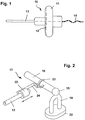
- FIG. 1 shows an implantable hearing aid transducer 10 on an enlarged scale designed, for example, as a piezo transducer for vibratory stimulation of the ossicular chain can be.
- the hearing aid converter has a hermetically sealed on all sides, biocompatible housing 11, and it can be used with an electromechanically active Heteromorphic composite element of the type known from EP-A-0 499 940.
- an actively vibratable part 12 of the Hearing aid converter 10 With an actively vibratable part 12 of the Hearing aid converter 10, a coupling rod 13 is mechanically firmly connected.
- Im illustrated Embodiment has the coupling rod 13 essentially on it entire length the shape of a straight cylinder.
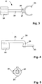
- Fig. 2 shows a schematic perspective view of a for connecting the coupling rod 13 with the long anvil extension 16 designed coupling element 17.
- a such coupling is suitable for an intact ossicular chain. 2 are the Anvil-stapes joint 18, the stapes superstructure 19 and the stapes footplate 20 shown schematically.
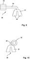
- the coupling element 17 has a crimp sleeve 22, a C-shaped one Coupling part 23 and a central part 24, which for a fixed mutual connection of crimp sleeve 22 and coupling part 23.
- the coupling element 17 is in further enlarged scale in FIGS. 3, 4 and 5.
- the middle part 24 consists of an angled piece of wire, one leg 25 elongated and connected to the outside of the crimp sleeve 22, e.g. soldered or welded.
- the other, shorter leg 26 of the middle part 24 engages its free end into an eyelet 27 formed on the coupling part 23. He is there for example by welding or soldering.
- the C-shaped Coupling part 23 can in particular be made of a pure titanium foil (purity> 99.6%) with a Thickness on the order of 200 microns wire-eroded.
- a coupling element 29 corresponding to a modified, also particularly suitable for coupling to the long anvil extension 16 Embodiment shown.
- the crimp sleeve 22 is in a fixed connection (for example Welded or soldered connection) with a first cylindrical section 30 of a central part 31, designated overall by 31.
- a tapered section 32 On the cylindrical section 30 adjoins a tapered section 32, which into a second cylindrical Section 33 merges. Its diameter is smaller than that of section 30.
- the cylindrical section 33 is in one piece with a band loop 34, which can be placed around the long anvil extension 16, for example.
- the figures 9 and 10 show a further modified coupling element 36. This is before especially suitable for coupling to the stapes head in the absence of anvil.
- the Coupling element 36 differs from coupling element 17 of FIGS. 2 to 5 in essentially in that instead of the C-shaped coupling part 23 on the central part 24 an approximately bell-shaped coupling part 37 is attached.
- the coupling part 37 can the gold bell of conventional gold wire BELL prostheses (see Steinbach, E .; Pusalkar, A.G .; Plester, D. (1990): Replacement of the ossicles with gold prostheses.
- the coupling part 37 leaves sit on the stapes head and there by squeezing the Fix bell parts 38.
- FIGS. 11 and 12 illustrated type.
- a piston-shaped coupling part 41 according to Art a stapes piston prosthesis is provided, which has an angled middle part 42 the crimp sleeve 22 is firmly connected and an integral extension of the Crimp sleeve 22 remote leg 43 of the middle part 42.
- the coupling rod 13 as an "artificial anvil” through the Chorda-facial angle led into the middle ear and its distal end over the oval Niche to be positioned.
- the coupling element 40 becomes similar to a stapedectomy set and attached to the coupling rod 13. The coupling part then dips over the Perforation into the vestibule.
- the coupling parts mentioned are similar to those of proven standard elements of middle ear prostheses, and they offer the advantage that they can be used with common Standard surgical instruments, such as McGee forceps, jaws, Double spoons or hooks mechanically closed, but also if necessary can be opened again.
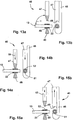
- a hammer head punch known per se is particularly suitable for crimping in situ (e.g. STORZ 222800), which in the cutting area in the from the fig. 13 to 15 visible Was modified.
- the crimping tool so adapted to the present purpose has a stationary part 46 and a displaceable with respect to the stationary part Part 47 on.
- the crimping tool parts 46 and 47 are opposed to each other arcuate cutting 48 and 49 equipped, the radius of curvature of the Radius of the crimp sleeve 22 is adapted., Preferably the radius of curvature of the Cutting is slightly larger than the outer radius of the crimp sleeve.
- the cutting edge 48 of the stationary crimping tool part can be used to fasten the crimp sleeve 22 46 against the crimp sleeve 22 brought into the desired position corresponding to the Fig. 13a and 13b are created. Then the cutting edge 49 is moved by moving the Crimping tool part 46 in the direction of arrow 50 on the cutting edge 48 of the stationary Crimping tool part 46 moved. By applying an appropriate crimping force the crimp sleeve 22 by means of the cutting edges 48, 49 in the area of two to one another diametrically opposed, arcuate crimp zones 51, 52, which are in Extend circumferential direction of the crimp sleeve 22, cold-flow deformed (Figs. 14a and 14b). Then, by moving the crimping tool part 47 in the direction of arrow 53 the cutting edge 49 moves away from the cutting edge 48 (FIGS. 15a and 15b), whereupon the Crimping tool 45 is brought out of the middle ear area.
- a crimp angle ⁇ (FIG. 13a) worked from approximately 90 °.
- the crimp angle ⁇ corresponds to intraoperatively the angle between the external auditory canal through which the crimping tool 45 is enaural is inserted into the middle ear, and the longitudinal axis of the coupling rod 13.
- the crimping tool 45 is also useful with a mechanical overload protection (not shown in detail) for avoidance provided excessively large operators.
- the crimp sleeve by means of the crimping tool is plastically cold-deformable, while the coupling rod 13 is at least has a rough surface in the fixing area and under the influence of the Crimping tool is not plastically cold deformable.
- An averaged Roughing depth Rz of at least 10 ⁇ m is for the rough outer surface of the coupling rod 13 particularly expedient in the area of the connection to the crimp sleeve 22.
- the crimp sleeve 22 preferably consists of gold, in particular of fine gold a gold content> 99.99%, which is preferably soft annealed.
- the soft glow can be conveniently for about 10 minutes at a temperature of the order of magnitude of 500 ° C.
- Such soft annealed fine gold can have a hardness HV of about 20, for example.
- the smallest possible number of different bio-metals should be used for the hearing implant can be used to generate an unwanted potential corresponding to the exclude or minimize electrochemical voltage series.
- the material is biocompatibility and long-term stability especially for middle ear spaces sufficiently occupied.
- there is a postoperative releasability of the ossicle coupling still given after several years of body time. Such The connection is broken using adequate force and using ear surgical standard instruments possible.
- the connection of the coupling element 17, 19, 36, 40 can be based on the respective target ossicle or the perilymph on proven standard elements of common passive middle ear prostheses happen.
- Implantable titanium is particularly suitable for the coupling rod 13, in particular Pure titanium with a purity> 99.6%.
- platinum, niobium or tantalum Alloys of titanium, platinum, niobium or tantalum are considered.
- the Coupling rod 13 but also made of an implantable ceramic material, in particular Aluminum oxide.
- the material and constructive design make sure that it it depends on the vibratory stimulus (action) of the transducer 10 being as lossless as possible, i.e. reverberant to introduce into the target ossicle or perilymph.
- the total mass of the coupling elements is preferably below the mass of the anvil, which averages 25 mg.
- the lowest possible weight of the coupling elements also leads to a reduction in inertial forces when accelerated by external forces Influences such as shock, vibration, etc.
- the cold flow connection explained in detail above can also be used for elements of a passive hearing implant that can be used as a total or partial replacement for the ossicular chain is trained.
- An exemplary embodiment of a total prosthesis is shown schematically in Fig. 16 is shown at 58, while Fig. 17 is a similar schematic representation Example of a partial prosthesis 59 shows.
- the total prosthesis 58 has a connecting element 61 with a drum head-side coupling part 62 for coupling the prosthesis the eardrum and a hollow cylinder part 63 firmly connected to it. Of the At its end remote from the coupling part 62, the cylinder part 63 goes into the Crimp sleeve 22 over.
- the implant 58 also includes one in the crimp sleeve 22 and if necessary, the coupling rod 64 immersing the cylinder part 63.
- the coupling rod 64 is at least in the fixing area in the manner explained above for the coupling rod 13 provided with a rough surface, and it goes in the illustrated embodiment integrally into the piston-shaped coupling part 41, which has an opening the stapes footplate 20 is immersed in the perilymph.
- the coupling part 41 carries on his from the end of the crimp sleeve 22, for example an annular end Stop 65 for limiting the immersion depth of the coupling part 41.
- the partial prosthesis according to FIG. 17 differs from the total prosthesis of FIG. 16 in essentially only in that the end of the coupling rod remote from the coupling part 62 64 is connected to the bell-shaped coupling part 37, which, as above described, can be placed on the head of stapes.
- the connecting element 61 can be and rotate the coupling rod 64 in the same way as explained above and in Adjust the axial direction and connect to one another permanently and without play by crimping. In this way, the length of the patient can be easily and quickly customized Total or partial denture and, if necessary, mutual angular alignment the coupling parts 62 and 41 and 37 set intraoperatively become.
- the figures 18, 19 and 20 show a further modified embodiment of a Arrangement for adjusting the relative position of two elements of a hearing implant and to fix these elements in the set relative position.
- a coupling element 67 the piston-shaped coupling part 41 according to FIGS. 11, 12 and 16 and one connected via an intermediate link 68 to strap loop 69, which around the Coupling rod 13 can be drawn around.
- the band loop 69 encloses the coupling rod 13 over an angle of at least 360 ° to by force and / or positive engagement for a Fixing the strap loop 69 with respect to the coupling rod 13 in the respectively set Position.
- the C-shaped coupling part 23 or the band loop 34 or the bell-shaped coupling part 37 can be provided can instead of the piston-shaped coupling part 41. In a corresponding manner, this can be done in the partial prosthesis according to FIG. 17 bell-shaped coupling part 37 through the C-shaped coupling part 23 or the band loop 34 replace.
- the described can also be used with regard to other features Arrangements vary easily. For example, using the crimping tool 45 two or more crimp zones side by side in successive crimping operations be formed, or the crimping tool can be with two or more side by side Pairs of cutters. Among other things, it is also possible to replace one of the two cutting edges 48, 49 by an anvil-like counterpart and to form only one of the crimp zones 51 and 52.
Landscapes
- Health & Medical Sciences (AREA)
- General Health & Medical Sciences (AREA)
- Otolaryngology (AREA)
- Engineering & Computer Science (AREA)
- Oral & Maxillofacial Surgery (AREA)
- Transplantation (AREA)
- Acoustics & Sound (AREA)
- Signal Processing (AREA)
- Pulmonology (AREA)
- Cardiology (AREA)
- Neurosurgery (AREA)
- Physics & Mathematics (AREA)
- Biomedical Technology (AREA)
- Heart & Thoracic Surgery (AREA)
- Vascular Medicine (AREA)
- Life Sciences & Earth Sciences (AREA)
- Animal Behavior & Ethology (AREA)
- Public Health (AREA)
- Veterinary Medicine (AREA)
- Prostheses (AREA)
Applications Claiming Priority (2)
| Application Number | Priority Date | Filing Date | Title |
|---|---|---|---|
| DE19738587A DE19738587C1 (de) | 1997-09-03 | 1997-09-03 | Anordnung zum Einstellen und Fixieren der Relativlage zweier Elemente eines aktiven oder passiven Hör-Implantats |
| DE19738587 | 1997-09-03 |
Publications (3)
| Publication Number | Publication Date |
|---|---|
| EP0901779A2 true EP0901779A2 (fr) | 1999-03-17 |
| EP0901779A3 EP0901779A3 (fr) | 2006-03-15 |
| EP0901779B1 EP0901779B1 (fr) | 2008-08-06 |
Family
ID=7841116
Family Applications (1)
| Application Number | Title | Priority Date | Filing Date |
|---|---|---|---|
| EP97118092A Expired - Lifetime EP0901779B1 (fr) | 1997-09-03 | 1997-10-17 | Dispositif permettant de régler et fixer la position relative de deux éléments d'une prothèse auditive active ou passive |
Country Status (6)
| Country | Link |
|---|---|
| US (1) | US5941814A (fr) |
| EP (1) | EP0901779B1 (fr) |
| AU (1) | AU712964B2 (fr) |
| CA (1) | CA2242235C (fr) |
| DE (2) | DE19738587C1 (fr) |
| DK (1) | DK0901779T3 (fr) |
Cited By (9)
| Publication number | Priority date | Publication date | Assignee | Title |
|---|---|---|---|---|
| DE19931788C1 (de) * | 1999-07-08 | 2000-11-30 | Implex Hear Tech Ag | Anordnung zum mechanischen Ankoppeln eines Treibers an eine Ankoppelstelle der Ossikelkette |
| DE19935029C2 (de) * | 1999-07-26 | 2003-02-13 | Phonak Ag Staefa | Implantierbare Anordnung zum mechanischen Ankoppeln eines Treiberteils an eine Ankoppelstelle |
| EP1054573A3 (fr) * | 1999-05-21 | 2006-01-04 | Phonak Ag | Dispositif pour le couplage mécanique d'un transducteur électromécanique de prothèse auditive implantable dans une cavité dans la mastoidite |
| EP1759662A1 (fr) * | 2005-09-06 | 2007-03-07 | Clarity Corporation | Prothèse de l'oreille moyenne avec une aide de sertissage |
| EP1774925A1 (fr) * | 2005-10-11 | 2007-04-18 | Heinz Kurz GmbH Medizintechnik | Prothèse d'osselets de l'oreille à joint articulé élastique |
| EP1091619A3 (fr) * | 1999-10-07 | 2009-10-07 | Phonak Ag | Dispositif pour le couplage mécanique d'un vibreur à un place de couplage du chaîne ossicullair |
| EP1094687A3 (fr) * | 1999-10-07 | 2009-10-07 | Phonak Ag | Dispositif pour le couplage mécanique d'un vibreur à un place de couplage du chaîne ossicullair |
| EP2030595A3 (fr) * | 2007-08-31 | 2009-10-21 | Heinz Kurz GmbH Medizintechnik | Prothèse d'osselets d'oreille à longueur variable |
| EP3005982A1 (fr) * | 2014-10-07 | 2016-04-13 | Heinz Kurz GmbH Medizintechnik | Implant auditif actif comprenant une fixation reglable de l'embout d'actionneur dans l'oreille moyenne |
Families Citing this family (38)
| Publication number | Priority date | Publication date | Assignee | Title |
|---|---|---|---|---|
| US6267731B1 (en) | 1998-06-05 | 2001-07-31 | St. Croix Medical, Inc. | Method and apparatus for reduced feedback in implantable hearing assistance systems |
| US6077215A (en) * | 1998-10-08 | 2000-06-20 | Implex Gmbh Spezialhorgerate | Method for coupling an electromechanical transducer of an implantable hearing aid or tinnitus masker to a middle ear ossicle |
| DE19859171C2 (de) * | 1998-12-21 | 2000-11-09 | Implex Hear Tech Ag | Implantierbares Hörgerät mit Tinnitusmaskierer oder Noiser |
| DE19914993C1 (de) * | 1999-04-01 | 2000-07-20 | Implex Hear Tech Ag | Vollimplantierbares Hörsystem mit telemetrischer Sensorprüfung |
| DE19915684B4 (de) * | 1999-04-07 | 2005-12-01 | Phonak Ag | Implantierbares Positionier- und Fixiersystem für aktorische und sensorische Implantate |
| DE10015421C2 (de) | 2000-03-28 | 2002-07-04 | Implex Ag Hearing Technology I | Teil- oder vollimplantierbares Hörsystem |
| DE10018334C1 (de) * | 2000-04-13 | 2002-02-28 | Implex Hear Tech Ag | Mindestens teilimplantierbares System zur Rehabilitation einer Hörstörung |
| US6517476B1 (en) | 2000-05-30 | 2003-02-11 | Otologics Llc | Connector for implantable hearing aid |
| US6491622B1 (en) | 2000-05-30 | 2002-12-10 | Otologics Llc | Apparatus and method for positioning implantable hearing aid device |
| DE10031832C2 (de) * | 2000-06-30 | 2003-04-30 | Cochlear Ltd | Hörgerät zur Rehabilitation einer Hörstörung |
| DE10039401C2 (de) | 2000-08-11 | 2002-06-13 | Implex Ag Hearing Technology I | Mindestens teilweise implantierbares Hörsystem |
| DE20014659U1 (de) | 2000-08-24 | 2000-11-30 | Heinz Kurz GmbH Medizintechnik, 72144 Dußlingen | Vorrichtung zum Ankoppeln |
| DE10041726C1 (de) | 2000-08-25 | 2002-05-23 | Implex Ag Hearing Technology I | Implantierbares Hörsystem mit Mitteln zur Messung der Ankopplungsqualität |
| DE10047388C1 (de) | 2000-09-25 | 2002-01-10 | Implex Hear Tech Ag | Mindestens teilweise implantierbares Hörsystem |
| DE20101988U1 (de) * | 2001-02-06 | 2001-06-13 | Heinz Kurz GmbH Medizintechnik, 72144 Dußlingen | Vorrichtung zur Befestigung eines Magneten am menschlichen Mittelohr |
| DE10114838A1 (de) * | 2001-03-26 | 2002-10-10 | Implex Ag Hearing Technology I | Vollständig implantierbares Hörsystem |
| US6730015B2 (en) | 2001-06-01 | 2004-05-04 | Mike Schugt | Flexible transducer supports |
| EP1422971B1 (fr) * | 2002-11-20 | 2012-11-07 | Phonak Ag | Transducteur implantable pour des systèmes auditifs et procédé d'ajustement de la réponse en fréquence d'un tel transducteur |
| US7273447B2 (en) * | 2004-04-09 | 2007-09-25 | Otologics, Llc | Implantable hearing aid transducer retention apparatus |
| US7153257B2 (en) * | 2004-04-09 | 2006-12-26 | Otologics, Llc | Implantable hearing aid transducer system |
| US7186211B2 (en) | 2004-04-09 | 2007-03-06 | Otologics, Llc | Transducer to actuator interface |
| US7219177B2 (en) * | 2004-11-23 | 2007-05-15 | Winbond Electronics Corp. | Method and apparatus for connecting buses with different clock frequencies by masking or lengthening a clock cycle of a request signal in accordance with the different clock frequencies of the buses |
| WO2007011846A2 (fr) * | 2005-07-18 | 2007-01-25 | Soundquest, Inc. | Dispositif auditif integre dans l'oreille et ses procedes d'utilisation |
| US20070127757A2 (en) * | 2005-07-18 | 2007-06-07 | Soundquest, Inc. | Behind-The-Ear-Auditory Device |
| WO2007147071A2 (fr) * | 2006-06-14 | 2007-12-21 | Otologics, Llc | accouplement de compression d'un actionneur d'aide auditive implantable sur un composant auditif |
| WO2008033791A1 (fr) * | 2006-09-12 | 2008-03-20 | Med-El Elektromedizinische Geraete Gmbh | Structure de fixation de l'oreille moyenne |
| US7722525B2 (en) | 2007-05-24 | 2010-05-25 | Otologics, Llc | Lateral coupling of an implantable hearing aid actuator to an auditory component |
| US7822479B2 (en) * | 2008-01-18 | 2010-10-26 | Otologics, Llc | Connector for implantable hearing aid |
| US8262729B2 (en) * | 2008-07-08 | 2012-09-11 | Enteroptyx | Dynamic ossicular prosthesis |
| EP2135584B1 (fr) * | 2008-10-21 | 2011-01-19 | Franco Beoni | Dispositif de prothèse d'oreille moyenne |
| ATE523164T1 (de) * | 2009-09-14 | 2011-09-15 | Franco Beoni | Mittelohr-prothesenvorrichtung |
| DE102010046457B3 (de) | 2010-09-24 | 2011-07-07 | Heinz Kurz GmbH Medizintechnik, 72144 | Anordnung zur längenvariablen Fixierung des Aktor-Endstücks eines aktiven Hör-Implantats im Mittelohr |
| DE202010013586U1 (de) | 2010-09-24 | 2010-11-25 | Heinz Kurz Gmbh Medizintechnik | Anordnung zur längenvariablen Fixierung des Aktor-Endstücks eines aktiven Hör-Implantats im Mittelohr |
| US9119010B2 (en) * | 2011-12-09 | 2015-08-25 | Sophono, Inc. | Implantable sound transmission device for magnetic hearing aid, and corresponding systems, devices and components |
| IL218715A (en) * | 2012-03-19 | 2014-03-31 | Mor Research Applic Ltd | Middle ear prosthesis |
| DE202014104794U1 (de) | 2014-10-07 | 2014-10-29 | Heinz Kurz Gmbh Medizintechnik | Aktives Hör-Implantat mit einstellbarer Fixierung des Aktor-Endstücks im Mittelohr |
| US10321247B2 (en) | 2015-11-27 | 2019-06-11 | Cochlear Limited | External component with inductance and mechanical vibratory functionality |
| DE102023110157A1 (de) * | 2023-04-21 | 2024-10-24 | Med-El Elektromedizinische Geräte GmbH | Gehörknöchelchenprothese |
Citations (1)
| Publication number | Priority date | Publication date | Assignee | Title |
|---|---|---|---|---|
| EP0499940A1 (fr) | 1991-02-13 | 1992-08-26 | IMPLEX GmbH Spezialhörgeräte | Transducteur électromécanique pour appareils de correction auditive implantables |
Family Cites Families (11)
| Publication number | Priority date | Publication date | Assignee | Title |
|---|---|---|---|---|
| US3196462A (en) * | 1961-09-05 | 1965-07-27 | Robinson Mendell | Stapedial prosthesis |
| US3931648A (en) * | 1975-01-08 | 1976-01-13 | Richards Manufacturing Company | Stapedial prosthesis |
| US4655776A (en) * | 1984-01-12 | 1987-04-07 | Oto Enterprises, Inc. | Prostheses for ossicular reconstruction |
| DE3604648A1 (de) * | 1985-12-03 | 1987-08-20 | Toepholm & Westermann | Verfahren zum herstellen eines im-ohr-hoergeraetes |
| US4898183A (en) * | 1987-07-24 | 1990-02-06 | Cochlear Pty. Limited | Apparatus and method for insertion of cochlear electrode assembly |
| US4988333A (en) * | 1988-09-09 | 1991-01-29 | Storz Instrument Company | Implantable middle ear hearing aid system and acoustic coupler therefor |
| US5370689A (en) * | 1992-07-23 | 1994-12-06 | Xomed-Treace, Inc. | Method of implanting a middle ear prosthesis |
| US5433749A (en) * | 1993-03-08 | 1995-07-18 | Clifford; Jerome R. | Apparatus for enhancing hearing in an ear |
| US5772575A (en) * | 1995-09-22 | 1998-06-30 | S. George Lesinski | Implantable hearing aid |
| DE19618961B4 (de) * | 1996-05-10 | 2004-09-16 | Phonak Ag | Gerät zur elektromechanischen Stimulation und Prüfung des Gehörs |
| US5771298A (en) * | 1997-01-13 | 1998-06-23 | Larson-Davis, Inc. | Apparatus and method for simulating a human mastoid |
-
1997
- 1997-09-03 DE DE19738587A patent/DE19738587C1/de not_active Expired - Fee Related
- 1997-10-17 DE DE59712957T patent/DE59712957D1/de not_active Expired - Lifetime
- 1997-10-17 EP EP97118092A patent/EP0901779B1/fr not_active Expired - Lifetime
- 1997-10-17 DK DK97118092T patent/DK0901779T3/da active
-
1998
- 1998-03-17 US US09/042,805 patent/US5941814A/en not_active Expired - Lifetime
- 1998-06-30 CA CA002242235A patent/CA2242235C/fr not_active Expired - Fee Related
- 1998-09-02 AU AU83074/98A patent/AU712964B2/en not_active Ceased
Patent Citations (1)
| Publication number | Priority date | Publication date | Assignee | Title |
|---|---|---|---|---|
| EP0499940A1 (fr) | 1991-02-13 | 1992-08-26 | IMPLEX GmbH Spezialhörgeräte | Transducteur électromécanique pour appareils de correction auditive implantables |
Cited By (10)
| Publication number | Priority date | Publication date | Assignee | Title |
|---|---|---|---|---|
| EP1054573A3 (fr) * | 1999-05-21 | 2006-01-04 | Phonak Ag | Dispositif pour le couplage mécanique d'un transducteur électromécanique de prothèse auditive implantable dans une cavité dans la mastoidite |
| DE19931788C1 (de) * | 1999-07-08 | 2000-11-30 | Implex Hear Tech Ag | Anordnung zum mechanischen Ankoppeln eines Treibers an eine Ankoppelstelle der Ossikelkette |
| EP1067820A3 (fr) * | 1999-07-08 | 2009-09-30 | Phonak Ag | Dispositif pour le couplage mécanique d'un vibreur à un place de couplage du chaîne ossicullair |
| DE19935029C2 (de) * | 1999-07-26 | 2003-02-13 | Phonak Ag Staefa | Implantierbare Anordnung zum mechanischen Ankoppeln eines Treiberteils an eine Ankoppelstelle |
| EP1091619A3 (fr) * | 1999-10-07 | 2009-10-07 | Phonak Ag | Dispositif pour le couplage mécanique d'un vibreur à un place de couplage du chaîne ossicullair |
| EP1094687A3 (fr) * | 1999-10-07 | 2009-10-07 | Phonak Ag | Dispositif pour le couplage mécanique d'un vibreur à un place de couplage du chaîne ossicullair |
| EP1759662A1 (fr) * | 2005-09-06 | 2007-03-07 | Clarity Corporation | Prothèse de l'oreille moyenne avec une aide de sertissage |
| EP1774925A1 (fr) * | 2005-10-11 | 2007-04-18 | Heinz Kurz GmbH Medizintechnik | Prothèse d'osselets de l'oreille à joint articulé élastique |
| EP2030595A3 (fr) * | 2007-08-31 | 2009-10-21 | Heinz Kurz GmbH Medizintechnik | Prothèse d'osselets d'oreille à longueur variable |
| EP3005982A1 (fr) * | 2014-10-07 | 2016-04-13 | Heinz Kurz GmbH Medizintechnik | Implant auditif actif comprenant une fixation reglable de l'embout d'actionneur dans l'oreille moyenne |
Also Published As
| Publication number | Publication date |
|---|---|
| DE59712957D1 (de) | 2008-09-18 |
| DK0901779T3 (da) | 2008-11-24 |
| AU712964B2 (en) | 1999-11-18 |
| DE19738587C1 (de) | 1999-05-27 |
| CA2242235C (fr) | 2002-12-10 |
| US5941814A (en) | 1999-08-24 |
| EP0901779A3 (fr) | 2006-03-15 |
| EP0901779B1 (fr) | 2008-08-06 |
| CA2242235A1 (fr) | 1999-03-03 |
| AU8307498A (en) | 1999-03-18 |
Similar Documents
| Publication | Publication Date | Title |
|---|---|---|
| EP0901779B1 (fr) | Dispositif permettant de régler et fixer la position relative de deux éléments d'une prothèse auditive active ou passive | |
| EP1067820B1 (fr) | Dispositif pour le couplage mécanique d'un vibreur à un place de couplage du chaîne ossicullair | |
| DE19948375B4 (de) | Anordnung zum mechanischen Ankoppeln eines Treibers an eine Ankoppelstelle der Ossikelkette | |
| DE19923403C2 (de) | Vorrichtung zum mechanischen Ankoppeln eines in einer Mastoidhöhle implantierbaren elektromechanischen Hörgerätewandlers | |
| EP1073313B1 (fr) | Dispositif pour le couplage mécanique d'un vibreur à une place de couplage de la chaîne ossiculaire | |
| EP1094687B1 (fr) | Dispositif pour le couplage mécanique d'un vibreur à un place de couplage du chaîne ossicullair | |
| EP2434778B1 (fr) | Agencement de fixation variable en longueur de l'extrémité d'actionneur d'un implant auditif actif dans l'oreille moyenne | |
| EP2789311B1 (fr) | Prothèse d'osselet avec élément de fixation rembourré | |
| EP2210572B1 (fr) | Prothèse de l'osselet de l'oreille passive avec applicateur | |
| DE102005010705B3 (de) | Gehörknöchelchenprothese | |
| EP1017337A1 (fr) | Prothese de l'oreille moyenne | |
| EP2030595A2 (fr) | Prothèse d'osselets d'oreille à longueur variable | |
| DE29819892U1 (de) | Gehörknöchelprothese | |
| EP1191816A2 (fr) | Système auditif au moins partiellement implantable | |
| EP1774925B1 (fr) | Prothèse d'osselets de l'oreille à joint articulé élastique | |
| DE60015724T2 (de) | Mittelohrimplantat | |
| DE102014119224B3 (de) | Gehörknöchelchenprothese mit Spikes | |
| DE102014114494A1 (de) | Aktives Hör-Implantat mit einstellbarer Fixierung des Aktor-Endstücks im Mittelohr | |
| DE202005003782U1 (de) | Gehörknöchelchenprothese | |
| DE202005015944U1 (de) | Gehörknöchelchenprothese mit elastischem Drehgelenk | |
| DE202010013586U1 (de) | Anordnung zur längenvariablen Fixierung des Aktor-Endstücks eines aktiven Hör-Implantats im Mittelohr | |
| DE4407847A1 (de) | Mittelohr-Prothese | |
| DE202013101478U1 (de) | Gehörknöchelchenprothese mit aufgefüttertem Befestigungselement | |
| DE202014104794U1 (de) | Aktives Hör-Implantat mit einstellbarer Fixierung des Aktor-Endstücks im Mittelohr | |
| DE202009000935U1 (de) | Passive Gehörknöchelchenprothese mit Applikator |
Legal Events
| Date | Code | Title | Description |
|---|---|---|---|
| PUAI | Public reference made under article 153(3) epc to a published international application that has entered the european phase |
Free format text: ORIGINAL CODE: 0009012 |
|
| AK | Designated contracting states |
Kind code of ref document: A2 Designated state(s): AT BE CH DE DK ES FI FR GB GR IE IT LI LU MC NL PT SE |
|
| RTI1 | Title (correction) | ||
| RAP1 | Party data changed (applicant data changed or rights of an application transferred) |
Owner name: IMPLEX AKTIENGESELLSCHAFT HEARING TECHNOLOGY |
|
| RAP1 | Party data changed (applicant data changed or rights of an application transferred) |
Owner name: PHONAK AG |
|
| PUAL | Search report despatched |
Free format text: ORIGINAL CODE: 0009013 |
|
| AK | Designated contracting states |
Kind code of ref document: A3 Designated state(s): AT BE CH DE DK ES FI FR GB GR IE IT LI LU MC NL PT SE |
|
| 17P | Request for examination filed |
Effective date: 20060907 |
|
| AKX | Designation fees paid |
Designated state(s): CH DE DK FR GB IT LI NL |
|
| GRAP | Despatch of communication of intention to grant a patent |
Free format text: ORIGINAL CODE: EPIDOSNIGR1 |
|
| GRAS | Grant fee paid |
Free format text: ORIGINAL CODE: EPIDOSNIGR3 |
|
| GRAA | (expected) grant |
Free format text: ORIGINAL CODE: 0009210 |
|
| AK | Designated contracting states |
Kind code of ref document: B1 Designated state(s): CH DE DK FR GB IT LI NL |
|
| REG | Reference to a national code |
Ref country code: GB Ref legal event code: FG4D Free format text: NOT ENGLISH |
|
| REG | Reference to a national code |
Ref country code: CH Ref legal event code: NV Representative=s name: TROESCH SCHEIDEGGER WERNER AG Ref country code: CH Ref legal event code: EP |
|
| REF | Corresponds to: |
Ref document number: 59712957 Country of ref document: DE Date of ref document: 20080918 Kind code of ref document: P |
|
| REG | Reference to a national code |
Ref country code: DK Ref legal event code: T3 |
|
| PLBE | No opposition filed within time limit |
Free format text: ORIGINAL CODE: 0009261 |
|
| STAA | Information on the status of an ep patent application or granted ep patent |
Free format text: STATUS: NO OPPOSITION FILED WITHIN TIME LIMIT |
|
| 26N | No opposition filed |
Effective date: 20090507 |
|
| PGFP | Annual fee paid to national office [announced via postgrant information from national office to epo] |
Ref country code: NL Payment date: 20101015 Year of fee payment: 14 Ref country code: FR Payment date: 20101029 Year of fee payment: 14 Ref country code: DK Payment date: 20101006 Year of fee payment: 14 |
|
| PGFP | Annual fee paid to national office [announced via postgrant information from national office to epo] |
Ref country code: IT Payment date: 20101027 Year of fee payment: 14 Ref country code: GB Payment date: 20101005 Year of fee payment: 14 |
|
| REG | Reference to a national code |
Ref country code: NL Ref legal event code: V1 Effective date: 20120501 |
|
| GBPC | Gb: european patent ceased through non-payment of renewal fee |
Effective date: 20111017 |
|
| REG | Reference to a national code |
Ref country code: DK Ref legal event code: EBP |
|
| REG | Reference to a national code |
Ref country code: FR Ref legal event code: ST Effective date: 20120629 |
|
| PG25 | Lapsed in a contracting state [announced via postgrant information from national office to epo] |
Ref country code: NL Free format text: LAPSE BECAUSE OF NON-PAYMENT OF DUE FEES Effective date: 20120501 |
|
| PG25 | Lapsed in a contracting state [announced via postgrant information from national office to epo] |
Ref country code: IT Free format text: LAPSE BECAUSE OF NON-PAYMENT OF DUE FEES Effective date: 20111017 Ref country code: GB Free format text: LAPSE BECAUSE OF NON-PAYMENT OF DUE FEES Effective date: 20111017 Ref country code: FR Free format text: LAPSE BECAUSE OF NON-PAYMENT OF DUE FEES Effective date: 20111102 |
|
| PG25 | Lapsed in a contracting state [announced via postgrant information from national office to epo] |
Ref country code: DK Free format text: LAPSE BECAUSE OF NON-PAYMENT OF DUE FEES Effective date: 20111031 |
|
| PGFP | Annual fee paid to national office [announced via postgrant information from national office to epo] |
Ref country code: CH Payment date: 20121004 Year of fee payment: 16 |
|
| REG | Reference to a national code |
Ref country code: DE Ref legal event code: R082 Ref document number: 59712957 Country of ref document: DE Representative=s name: GRUENECKER PATENT- UND RECHTSANWAELTE PARTG MB, DE Ref country code: DE Ref legal event code: R082 Ref document number: 59712957 Country of ref document: DE Representative=s name: GRUENECKER, KINKELDEY, STOCKMAIR & SCHWANHAEUS, DE |
|
| PGFP | Annual fee paid to national office [announced via postgrant information from national office to epo] |
Ref country code: DE Payment date: 20131009 Year of fee payment: 17 |
|
| REG | Reference to a national code |
Ref country code: CH Ref legal event code: PL |
|
| PG25 | Lapsed in a contracting state [announced via postgrant information from national office to epo] |
Ref country code: LI Free format text: LAPSE BECAUSE OF NON-PAYMENT OF DUE FEES Effective date: 20131031 Ref country code: CH Free format text: LAPSE BECAUSE OF NON-PAYMENT OF DUE FEES Effective date: 20131031 |
|
| REG | Reference to a national code |
Ref country code: DE Ref legal event code: R119 Ref document number: 59712957 Country of ref document: DE |
|
| PG25 | Lapsed in a contracting state [announced via postgrant information from national office to epo] |
Ref country code: DE Free format text: LAPSE BECAUSE OF NON-PAYMENT OF DUE FEES Effective date: 20150501 |