EP0901784A2 - Halsmassagegerät für Bäder - Google Patents
Halsmassagegerät für Bäder Download PDFInfo
- Publication number
- EP0901784A2 EP0901784A2 EP98305082A EP98305082A EP0901784A2 EP 0901784 A2 EP0901784 A2 EP 0901784A2 EP 98305082 A EP98305082 A EP 98305082A EP 98305082 A EP98305082 A EP 98305082A EP 0901784 A2 EP0901784 A2 EP 0901784A2
- Authority
- EP
- European Patent Office
- Prior art keywords
- massager
- spa
- massagers
- held
- water
- Prior art date
- Legal status (The legal status is an assumption and is not a legal conclusion. Google has not performed a legal analysis and makes no representation as to the accuracy of the status listed.)
- Ceased
Links
- XLYOFNOQVPJJNP-UHFFFAOYSA-N water Substances O XLYOFNOQVPJJNP-UHFFFAOYSA-N 0.000 claims description 37
- 238000010276 construction Methods 0.000 description 2
- 210000003205 muscle Anatomy 0.000 description 2
- 239000004677 Nylon Substances 0.000 description 1
- 238000005299 abrasion Methods 0.000 description 1
- 229920001971 elastomer Polymers 0.000 description 1
- 239000000806 elastomer Substances 0.000 description 1
- 239000000463 material Substances 0.000 description 1
- 238000000034 method Methods 0.000 description 1
- 229920001778 nylon Polymers 0.000 description 1
- 229920000642 polymer Polymers 0.000 description 1
- 229920002635 polyurethane Polymers 0.000 description 1
- 239000004814 polyurethane Substances 0.000 description 1
- 230000003245 working effect Effects 0.000 description 1
Images




Classifications
-
- A—HUMAN NECESSITIES
- A61—MEDICAL OR VETERINARY SCIENCE; HYGIENE
- A61H—PHYSICAL THERAPY APPARATUS, e.g. DEVICES FOR LOCATING OR STIMULATING REFLEX POINTS IN THE BODY; ARTIFICIAL RESPIRATION; MASSAGE; BATHING DEVICES FOR SPECIAL THERAPEUTIC OR HYGIENIC PURPOSES OR SPECIFIC PARTS OF THE BODY
- A61H7/00—Devices for suction-kneading massage; Devices for massaging the skin by rubbing or brushing not otherwise provided for
- A61H7/002—Devices for suction-kneading massage; Devices for massaging the skin by rubbing or brushing not otherwise provided for by rubbing or brushing
- A61H7/004—Devices for suction-kneading massage; Devices for massaging the skin by rubbing or brushing not otherwise provided for by rubbing or brushing power-driven, e.g. electrical
-
- A—HUMAN NECESSITIES
- A61—MEDICAL OR VETERINARY SCIENCE; HYGIENE
- A61H—PHYSICAL THERAPY APPARATUS, e.g. DEVICES FOR LOCATING OR STIMULATING REFLEX POINTS IN THE BODY; ARTIFICIAL RESPIRATION; MASSAGE; BATHING DEVICES FOR SPECIAL THERAPEUTIC OR HYGIENIC PURPOSES OR SPECIFIC PARTS OF THE BODY
- A61H2201/00—Characteristics of apparatus not provided for in the preceding codes
- A61H2201/12—Driving means
- A61H2201/1238—Driving means with hydraulic or pneumatic drive
-
- A—HUMAN NECESSITIES
- A61—MEDICAL OR VETERINARY SCIENCE; HYGIENE
- A61H—PHYSICAL THERAPY APPARATUS, e.g. DEVICES FOR LOCATING OR STIMULATING REFLEX POINTS IN THE BODY; ARTIFICIAL RESPIRATION; MASSAGE; BATHING DEVICES FOR SPECIAL THERAPEUTIC OR HYGIENIC PURPOSES OR SPECIFIC PARTS OF THE BODY
- A61H2203/00—Additional characteristics concerning the patient
- A61H2203/02—Additional characteristics concerning the patient immersed in liquid
-
- A—HUMAN NECESSITIES
- A61—MEDICAL OR VETERINARY SCIENCE; HYGIENE
- A61H—PHYSICAL THERAPY APPARATUS, e.g. DEVICES FOR LOCATING OR STIMULATING REFLEX POINTS IN THE BODY; ARTIFICIAL RESPIRATION; MASSAGE; BATHING DEVICES FOR SPECIAL THERAPEUTIC OR HYGIENIC PURPOSES OR SPECIFIC PARTS OF THE BODY
- A61H2205/00—Devices for specific parts of the body
- A61H2205/04—Devices for specific parts of the body neck
Definitions
- the field of the invention is muscle massagers and the invention relates more particularly to neck and shoulder massagers of the type which tend to be used with spas, hot tubs or whirlpool baths.
- a hydro-massage unit for a spa is shown in U.S. Patent No. 4,839,930. This device provides a flow of water against the inner surface of a diaphragm which provides a massage for a user's neck.
- a waterproof vibrating cushion is shown in U.S. Patent No. 4,935,972. It is waterproof and may be used in a spa or a bath tub. It utilizes a vibrator element within a cushion.
- the present invention is for a neck and upper shoulder massager for mounting in a spa, whirlpool bath or the like.
- the neck and upper shoulder massager is held in a housing which may be held in or against the sidewall of a spa.
- the massager has a massager body held in an opening in the sidewall or against the opening in the sidewall of the spa in a waterproof manner so that no water may be passed into the massager body.
- a waterproof massager diaphragm is held in a watertight manner over a diaphragm opening in the massager body. At least two massagers are held in a moveable manner by the massager body.
- Each massager has a massager face which contacts an underside of the waterproof massager diaphragm and each of the massagers is supported so that they are capable of moving in an undulating manner under the waterproof massager diaphragm.
- the massagers may be turned either by a motor held within the massager body, a motor which drives a driven cable within a hollow conduit attached to a remote motor and to the massager body or by water power driving a turbine held within the massager body.
- the massagers may be rotating angled arms or rotating angled massage wheels or cams.
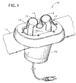
- Figure 1 is a perspective view partially cut away of the neck massager of the present invention.
- Figure 2 is a cross-sectional view thereof showing one of the massage knobs.
- Figure 3 is a cross-sectional view thereof showing both of the massage knobs.
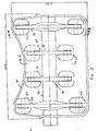
- Figure 4 is a top view with the diaphragm removed of the spa of Figure 1.
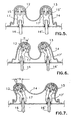
- Figure 5 is a cross-sectional view of the knobs in a central position.
- Figure 6 is a cross-sectional view of the knobs in an inner position.
- Figure 7 is a cross-sectional view of the knobs in an outer position.
- Figure 8 is a diagrammatic side view, partly in cross section, of an alternate embodiment of a massager positioned in a spa.
- Figure 9 is an enlarged cross sectional view, partly cut away of the drive cable of the massager of Figure 8.
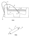
- Figure 10 is a diagrammatic side view, partly in cross section, of a further alternate embodiment of a massager positioned in a spa.
- Figure 11 is a side view partly in cross-section of an alternate embodiment of the neck massager of the present invention.
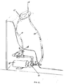
- Figure 12 is a side view of a spa and neck massager of the present invention driven by water power.
- Figure 13 is a cross-sectional view of an alternate embodiment of the massager arms of the massager of the present invention.
- Figure 14 is a cross-sectional view taken along line 14-14 of Figure 13.
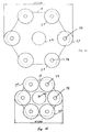
- Figure 15 is a cross-sectional view taken along line 15-15 of Figure 13.
- a neck massager for spas is shown in perspective view in Figure 1 and indicated generally by reference character 10.
- the neck massager of Figure 1 is designed to be mounted in the sidewall of a spa 11 in a waterproof manner. It is preferably mounted at an angle of about 45° to the horizontal.
- the massager has a pair of knobs 12 and 13 below a flexible diaphragm 14.
- the inner workings are shown best in Figures 2 and 3 where it can be seen that knob 12 is held on a shaft 15 which is turned by a bent fitting 17 affixed to shaft 16.
- the bent fitting 17 causes the tip 18 of knob 12 to be offset a distance 19 from the axis of rotation 20 of massage arm shaft 16.
- Distance should be between about 0.5" and 2.0" and preferably about 1.0".
- Bent fitting 17 is preferably at an angle of about 30°.
- An electric motor 21 is held within housing 22 as are a series of gears 23.
- Motor 21 has a driven shaft 24 to which an output gear 25 is held.
- Output gear 25 drives gear 26 which has a smaller gear 27 around the shaft 28' thereof.
- Smaller gear 27 drives gear 28 which also has a smaller gear 29 in its center.
- Smaller gear 29 in turn drives gear 30 which is attached to shaft 16.
- gear 30 drives a pair of idler gears 31 and 32 which in turn drive gear 33 in the opposite direction from gear 30.
- gear 30 drives a pair of idler gears 31 and 32 which in turn drive gear 33 in the opposite direction from gear 30.
- gear 33 With a 1500 RPM motor the massage gears 30 and 33 rotate at a speed of about 30 RPM which provides a slow and pleasant massage action by the movement of knobs 12 and 13 under diaphragm 14.
- Diaphragm 14 is fabricated from a flexible material preferably an elastomer such as polyurethane.
- the diaphragm 14 is preferably waterproof as is the gear box 34 portion of housing 22. Housing 22 is covered by a weatherproof cover 38.
- An O-ring seal 35 preferably is held by a series of bolts and nuts to the spa shell 11.
- the unit is shown in Figure 3 without gears where the support for shafts 16 and 16' can be seen to be held in shaft cups 39 and 39'.
- the other gears are similarly supported.
- the wall mounted massager of the present invention is preferably mounted in a flattened portion of a spa fabricated especially for the use of such massager, although other mounting methods can be used to adapt existing spas to the use of the massager of the present invention.
- the knobs preferably each have a rounded hemi- spherical ends having a diameter of about 1.5".
- the knobs are preferably fabricated from a polymer having a high degree of surface slip and abrasion resistance such as nylon, and with the knobs operating in opposite directions, the massaging action is especially effective.
- a cable driven version of the massager of the present invention is shown in Figure 8 and indicated by reference character 40.
- Two massage units are shown in the spa 41 and these may be hand held or attached to a spa wall by suction cups or other means.
- the massage unit is identical to that shown in Figures 1 through 7 except that in place of motor 21 a drive cable 42 is utilized.
- Drive cable 42 is flexible and, as shown in Figure 10 has a stationary outer sleeve or conduit 43 and a rotating inner driven cable 44.
- Such cables are used in a smaller version as speedometer cables and in larger versions to remotely drive a tool.
- Inner cable 44 would be attached to driven shaft 24 so that it is driven by inner cable 44 in place of motor 21.
- Inner cable 44 is driven by motor 45.
- Motor 45 is shown attached to an outer portion of spa 41 and is provided with means to protect the motor from the elements and to prevent the motor from being touched by users of the spa.
- the use of a cable driven massager permits the user to position the massager 40 in any preferred location.
- the massager 40 can be operated under the surface 54 of the water in the spa. Both the hollow flexible conduit 43 and the body of the massager are waterproof as is the diaphragm. Thus, the massager 40 of Figure 8 can be positioned at any desirable position.
- FIG. 10 A different version of a hand held massager is shown in Figure 10 and indicated by reference character 46.
- Massager 46 is also like massager 40 except that it is driven by a water turbine which turns driven shaft 24. Water is fed through hose 47 into massager 46 which contains a conventional turbine, not shown. Water is supplied from within spa 48 through conduit 49. Conduit 49 is affixed to the inlet of pump 50 which is driven by motor 51. Pump 50 feeds water at a high pressure to conduit 52 which, in turn, is attached to flexible hose 47. The water from the massager turbine simply drains back into the spa as indicated at reference character 53.
- a spa wall-mounted massager 55 is shown in Figure 11 and this massager is driven by the hollow flexible cable 42 of Figure 9.
- the motor 45 is positioned behind spa wall 56 and at a level below spa seat 57 and above the bottom 58 of spa 41. In this way, motor 45 is protected from any contact by the user. It is shown in Figure 11 attached to the outer wall 60 of the spa.
- the massager body or housing 22 is shown mounted in a manner similar to that shown in Figure 1 and the diaphragm 14 is held about diaphragm opening 61 in a waterproof manner similar to that shown in Figure 1.
- At least two massage arms 62 and 63 are shown in Figure 11 and they may be of any construction as long as they provide an undulating motion to waterproof diaphragm 14.
- a water driven massager is shown in Figure 12 and the massager body 22 is the same as that shown in Figure 10.
- a pump motor 64 drives a high pressure water pump 65 which provides high pressure water to the jets of the spa (not shown) through pipe 66.
- On/off valves 67 and 68 control the flow of water to the jets and the massager respectively.
- a conduit 69 feeds water to a turbine not shown, but of conventional construction which turns the massager arms in a manner similar to that described above.
- a water outlet conduit 70 is attached to the outlet of the turbine not shown and is connected to an inlet line 71 of pump 65.
- FIG. 13 An alternate embodiment of a massager unit is shown in Figures 13, 14 and 15 of the drawings.
- the massager body supports a massager wheel support shaft 72 to which massage wheels 73, 74, 75 and 76 are rigidly mounted. Wheels 73, 74, 75 and 76 support six rollers 77 rotatingly mounted on axles 78.
- Massage wheel support shaft 72 is driven by a belt not shown. Rollers 77 cause the flexible diaphragm 14 to undulate and provide a massaging action against the user's neck.
- a neck and upper massager may be held either by a spa wall or against a spa wall and is provided with a waterproof housing and diaphragm so that it may be used in a spa environment.
- the portable version may be moved to any comfortable position either above the water level or below it and the motor which drives the massager is safely held out of the way below the spa wall.
Landscapes
- Health & Medical Sciences (AREA)
- Life Sciences & Earth Sciences (AREA)
- Epidemiology (AREA)
- Pain & Pain Management (AREA)
- Physical Education & Sports Medicine (AREA)
- Rehabilitation Therapy (AREA)
- Dermatology (AREA)
- Animal Behavior & Ethology (AREA)
- General Health & Medical Sciences (AREA)
- Public Health (AREA)
- Veterinary Medicine (AREA)
- Massaging Devices (AREA)
- Percussion Or Vibration Massage (AREA)
Applications Claiming Priority (2)
| Application Number | Priority Date | Filing Date | Title |
|---|---|---|---|
| US08/911,041 US5984883A (en) | 1997-04-08 | 1997-08-14 | Neck massager for use in spas |
| US911041 | 1997-08-14 |
Publications (2)
| Publication Number | Publication Date |
|---|---|
| EP0901784A2 true EP0901784A2 (de) | 1999-03-17 |
| EP0901784A3 EP0901784A3 (de) | 2000-01-12 |
Family
ID=25429681
Family Applications (1)
| Application Number | Title | Priority Date | Filing Date |
|---|---|---|---|
| EP98305082A Ceased EP0901784A3 (de) | 1997-08-14 | 1998-06-26 | Halsmassagegerät für Bäder |
Country Status (3)
| Country | Link |
|---|---|
| US (1) | US5984883A (de) |
| EP (1) | EP0901784A3 (de) |
| BR (1) | BR9804523A (de) |
Cited By (1)
| Publication number | Priority date | Publication date | Assignee | Title |
|---|---|---|---|---|
| WO2004078090A3 (en) * | 2003-03-07 | 2005-01-13 | Carisma S R L | Hydrotherapeutic bathtub |
Families Citing this family (13)
| Publication number | Priority date | Publication date | Assignee | Title |
|---|---|---|---|---|
| US6387063B1 (en) * | 1999-11-03 | 2002-05-14 | Joseph Elnar | Vertically-oscillating spa massager |
| US6539560B1 (en) | 2000-10-24 | 2003-04-01 | Amanda Jill Grieco | Head support device |
| US6641548B2 (en) * | 2002-02-11 | 2003-11-04 | Joseph G. Elnar | Water driven vibrating massager |
| JP2003310689A (ja) * | 2002-04-18 | 2003-11-05 | Marutaka Co Ltd | 可搬型マッサージ機 |
| US7276034B1 (en) * | 2004-02-27 | 2007-10-02 | Elnar Joseph G | Water driven roller massager |
| US7996932B2 (en) * | 2008-03-28 | 2011-08-16 | Elnar Joseph G | Spa wall mounted water jet neck and shoulder massager |
| FR2941149B1 (fr) * | 2009-01-16 | 2013-10-18 | New Bath | Dispositif de massage pour une baignoire ou une cabine de douche |
| CN107126128B (zh) * | 2017-06-20 | 2023-08-04 | 九牧厨卫股份有限公司 | 一种内置多功能按摩枕的浴缸及组装方法 |
| UA130799U (uk) * | 2018-06-14 | 2018-12-26 | Микола Григорович Ляпко | Масажер |
| RU2711494C1 (ru) * | 2018-08-31 | 2020-01-17 | Николай Григорьевич Ляпко | Массажер |
| CN109907964A (zh) * | 2019-03-29 | 2019-06-21 | 合肥和正医疗科技有限公司 | 一种按摩头和颈部按摩器 |
| US12485062B2 (en) | 2020-08-21 | 2025-12-02 | Kohler Co. | Bath massage chair and pillow |
| CN215021900U (zh) * | 2021-07-12 | 2021-12-07 | 金成� | 多点式揉捏震动按摩设备 |
Family Cites Families (9)
| Publication number | Priority date | Publication date | Assignee | Title |
|---|---|---|---|---|
| US2384427A (en) * | 1942-01-19 | 1945-09-11 | Andis Clipper Co | Massage apparatus |
| US3322117A (en) * | 1963-10-18 | 1967-05-30 | Mccaw Earl | Orbit circulation activator and mount therefor |
| DE3436389A1 (de) * | 1984-02-18 | 1986-04-10 | MAG Walter Frenkel Medizinische Apparate und Geräte, 7483 Inzigkofen | Funktionserweitertes walkrollenmassagegeraet |
| EP0343912B1 (de) * | 1988-05-27 | 1994-01-19 | Watkins Manufacturing Corporation | Massage-Einheit |
| US4839930A (en) * | 1988-05-27 | 1989-06-20 | Watkins Manufacturing Corporation | Dry hydro-massage unit for a spa tank |
| JP2915112B2 (ja) * | 1990-09-05 | 1999-07-05 | 株式会社日立製作所 | 情報用記録部材及びディスク用記録媒体 |
| US5183034A (en) * | 1991-12-23 | 1993-02-02 | Kabushiki Kaisha Japan Health | Portable vibration finger pressure massager |
| US5356369A (en) * | 1992-06-11 | 1994-10-18 | Kabushiki Kaisha Japan Health | Portable vibration finger pressure massager |
| US5695451A (en) * | 1993-09-28 | 1997-12-09 | Tetsuhiro Kawakami | Massaging apparatus |
-
1997
- 1997-08-14 US US08/911,041 patent/US5984883A/en not_active Expired - Lifetime
-
1998
- 1998-06-26 EP EP98305082A patent/EP0901784A3/de not_active Ceased
- 1998-08-14 BR BR9804523-7A patent/BR9804523A/pt not_active Application Discontinuation
Cited By (1)
| Publication number | Priority date | Publication date | Assignee | Title |
|---|---|---|---|---|
| WO2004078090A3 (en) * | 2003-03-07 | 2005-01-13 | Carisma S R L | Hydrotherapeutic bathtub |
Also Published As
| Publication number | Publication date |
|---|---|
| BR9804523A (pt) | 1999-11-16 |
| US5984883A (en) | 1999-11-16 |
| EP0901784A3 (de) | 2000-01-12 |
Similar Documents
| Publication | Publication Date | Title |
|---|---|---|
| US5984883A (en) | Neck massager for use in spas | |
| US5016617A (en) | Automatic body massaging apparatus | |
| US6047416A (en) | Therapeutic shower for enveloping purposes | |
| CA2480009A1 (en) | Bath apparatus with therapy centers | |
| US5605533A (en) | Touch activated foot massage device | |
| CA2329117A1 (en) | Massager | |
| EP0107661A1 (de) | Vorrichtung zur durchführung hydraulischer massagen. | |
| US20240009070A1 (en) | Automated skeletal musculature, joint, facia and skin therapy system and methods of use | |
| US6387063B1 (en) | Vertically-oscillating spa massager | |
| US20030040689A1 (en) | Deep tissue massage machine | |
| US3580246A (en) | Motor operated vibrator having solar type motion | |
| US5675846A (en) | Brush-massage shower installation | |
| US5902258A (en) | Massage device | |
| CA2231309C (en) | Neck massager for use in spas | |
| WO2006096545A2 (en) | Waterproof hydrotherapy limb massager | |
| US6581219B1 (en) | Rotary shower brush for mounting in a shower stall | |
| US3570478A (en) | Foot massager apparatus | |
| EP0190007B1 (de) | Gerät zur Körperreinigung | |
| JP2001128880A (ja) | 垢擦水洗淨機具 | |
| JPH04297259A (ja) | ハンドマッサージ器 | |
| RU2343897C2 (ru) | Прибор для ножных процедур | |
| JP2004081416A (ja) | 可搬型マッサージ機 | |
| KR960000390B1 (ko) | 혈액순환과 피로회복을 위한 안마기 | |
| KR102061519B1 (ko) | 운동 및 치료를 위한 수중워킹머신 | |
| CN2302008Y (zh) | 脚部按摩器 |
Legal Events
| Date | Code | Title | Description |
|---|---|---|---|
| PUAI | Public reference made under article 153(3) epc to a published international application that has entered the european phase |
Free format text: ORIGINAL CODE: 0009012 |
|
| AK | Designated contracting states |
Kind code of ref document: A2 Designated state(s): AT CH DE ES FR GB IT LI |
|
| AX | Request for extension of the european patent |
Free format text: AL;LT;LV;MK;RO;SI |
|
| PUAL | Search report despatched |
Free format text: ORIGINAL CODE: 0009013 |
|
| AK | Designated contracting states |
Kind code of ref document: A3 Designated state(s): AT BE CH CY DE DK ES FI FR GB GR IE IT LI LU MC NL PT SE |
|
| AX | Request for extension of the european patent |
Free format text: AL;LT;LV;MK;RO;SI |
|
| 17P | Request for examination filed |
Effective date: 20000427 |
|
| RAP1 | Party data changed (applicant data changed or rights of an application transferred) |
Owner name: ELNAR, JOSEPH G. |
|
| AKX | Designation fees paid |
Free format text: AT CH DE ES FR GB IT LI |
|
| 17Q | First examination report despatched |
Effective date: 20020625 |
|
| STAA | Information on the status of an ep patent application or granted ep patent |
Free format text: STATUS: THE APPLICATION HAS BEEN REFUSED |
|
| 18R | Application refused |
Effective date: 20040919 |