EP0901821B1 - Dispositif avec récipient de prélèvement - Google Patents
Dispositif avec récipient de prélèvement Download PDFInfo
- Publication number
- EP0901821B1 EP0901821B1 EP98115764A EP98115764A EP0901821B1 EP 0901821 B1 EP0901821 B1 EP 0901821B1 EP 98115764 A EP98115764 A EP 98115764A EP 98115764 A EP98115764 A EP 98115764A EP 0901821 B1 EP0901821 B1 EP 0901821B1
- Authority
- EP
- European Patent Office
- Prior art keywords
- assembly
- tube
- cylindrical wall
- collection
- outer member
- Prior art date
- Legal status (The legal status is an assumption and is not a legal conclusion. Google has not performed a legal analysis and makes no representation as to the accuracy of the status listed.)
- Expired - Lifetime
Links
Images

Classifications
-
- B—PERFORMING OPERATIONS; TRANSPORTING
- B01—PHYSICAL OR CHEMICAL PROCESSES OR APPARATUS IN GENERAL
- B01L—CHEMICAL OR PHYSICAL LABORATORY APPARATUS FOR GENERAL USE
- B01L3/00—Containers or dishes for laboratory use, e.g. laboratory glassware; Droppers
- B01L3/50—Containers for the purpose of retaining a material to be analysed, e.g. test tubes
- B01L3/508—Rigid containers without fluid transport within
- B01L3/5082—Test tubes per se
Definitions
- This invention relates to a specimen collection container assembly and more particularly to a collection container for collecting biological fluid specimens where a small quantity of fluid may be collected and retained in the container while maintaining a container size sufficient to be easily accommodated and/or compatible with standard clinical equipment and instrumentation.
- Blood samples and other biological fluid specimens are routinely taken and analyzed in hospital and clinical situations for various medical purposes. Collection, handling and testing of these samples typically requires the use of various medical testing instruments. As the blood and fluid specimens are usually collected in a standard sized collection tube, the medical instruments used to test the samples are designed to accommodate these standard sized collection tubes.
- Conventional blood collection tubes used in most clinical situations are elongated cylindrical containers having one end closed by a semi-spherical or rounded portion and an opposed open end. The open end may be sealed by a resilient cap or stopper.
- the tube defines a collection interior which collects and holds the blood sample.
- the most common size of these blood collection tubes are designed to accommodate approximately 10 ml of blood or other biological fluid samples.
- Illustrative of such blood collection tubes is the VACUTAINER® brand blood collection tube sold by Becton, Dickinson and Company, 1 Becton Drive, Franklin Lakes, NJ (registered trademark of Becton, Dickinson and Company).
- a phlebotomist or other medical technician typically obtains a specimen of the patient's blood in the tube by techniques well known in the art.
- the tube is then appropriately labeled and transferred from the site of collection to a laboratory or other location where the contents of the tube are analyzed.
- the tube may be supported by various medical instruments.
- the plasma or serum derived therefrom is processed and analyzed either manually, semiautomatically or automatically. In some cases, the specimen must first be dispensed from the collection tube to a sample test tube or cuvette.
- specimen containers such as those incorporating a "false bottom” have been proposed to achieve decreased volume capacity in conjunction with standard external dimensions.
- these various specimen containers are not compatible with standard clinical equipment and instrumentation due to their design.
- these specimen containers have false bottoms with a generally flat, planar bottom end and a circular shaped opening.
- a specimen collection container assembly according to the first part of claim 1 is described in US-A-3 807 955.
- An outer tube forums a blood sample tube.
- An inner tube forming an isolator cup is inserted into the open end of the outer tube.
- the outer tube is a blood collection tube that may be used for taking in a sample of body fluid.
- the outer tube containing the sample is placed in a centrifuge and the body fluid is separated with the cells in the bottom portion of the tube and clear fluid portion up above. The fluid portion is than transferred from the outer tube into an inner tube or cup.
- the cup is inserted in the open end of the outer tube and snapped down into place.
- the cups or inner tubes may be used to take in a smaller volume of liquids. The cup holding such liquid is inserted into the top of an outer tube which is empty. It is always the outer tube that is used for taking in a sample of body fluid.
- specimen containers include partial-draw tubes which have standard external dimensions with partial evacuation so that blood fills only a portion of the internal volume.
- partial-draw tubes exhibit a reduction in the draw rate of a sample which reduces the collection efficacy of such tubes.
- partial-draw tubes may result in an inconsistent fill volume which may alter test results.
- it is difficult to determine accurate sample quantities with such partial-draw tubes because the slow rate of sample draw is not consistently measurable.
- the specimen collection container assembly according to the present invention is defined by claim 1.
- the present invention is a specimen collection container assembly comprising an inner tube within an outer tube.
- the inner and outer tubes each comprise an open top portion, a closed bottom portion, a sidewall extending from the top portion to the bottom portion and an open end associated with the top portion.
- the dimensions of the inner tube are such that the inner tube fits within the outer tube.
- the assembly may further comprise a cap or a stopper.
- the internal volume of the inner tube is less than the internal volume of the outer tube.
- the internal volume of the outer tube is about the same as a standard-sized or full draw blood collection container assembly.
- the external dimensions of the inner tube are less than the external dimensions of the outer tube.
- the external dimensions of the outer tube are about the same as a standard-sized or full draw blood collection container assembly.
- a standard-sized blood collection container assembly has an outer diameter of about 13 millimeters, a length of about 75 millimeters and an internal volume of about 6 mL to about 10 mL.
- each tube is made from polyethylene terephthalate, polypropylene, polyethylene, polyethylene napthalate or copolymers thereof or glass.
- An advantage of the present invention is that it provides a full-draw blood collection container assembly having a reduced internal volume but with external dimensions about the same as a standard-sized blood collection container assembly.
- a further advantage of the present invention is that the assembly provides a means for adapting a full-draw blood collection tube to handle a reduced internal volume for handling by equipment configured to handle standard-sized blood collection tubes having standard external dimensions.
- the assembly of the present invention provides a blood collection tube having full draw external dimensions but with a reduced internal volume as compared to standard-sized full draw blood collection tubes.
- the assembly of the present invention therefore addresses the need for a full-draw low-volume blood collection container assembly that presents the external dimensions of a standard-sized blood collection tube.
- the assembly of the present invention may be used to reliably collect small samples of blood or biological fluids and to maintain the integrity of the samples during storage and transport as compared to using standard-sized blood collection tubes.
- the assembly of the present invention can also be accommodated by standard-sized blood collection, transportation, storage, and diagnostic equipment.
- the assembly of the present invention may be used to reliably collect small samples of blood or biological fluids without being under partial pressure.
- the assembly of the present invention is therefore compatible with existing instrumentation, labels, and bar code readers and obviates the need for new instrumentation and handling devices or procedures that would be required for smaller or varying sized tubes.
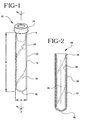
- FIGS. 1 and 2 show a typical standard sized blood collection tube 10 , having a sidewall 12 extending from an open end rim 14 to a closed end 16 and an interior area 18 .
- Sidewall 12 has an inner wall surface 20 and an outer wall surface 22 .
- a cap or stopper 24 may be on the open end rim 14 of tube 10 .
- Tube 10 is most preferably a standard-sized blood collection tube having an outer diameter A of about 13 millimeters, a length B of about 75 millimeters, and an internal volume of about 10 milliliters.
- Interior area 18 is typically maintained at a lower-than-atmospheric internal pressure so that when a blood collection probe penetrates through the cap placing interior area 18 in communication with the circulatory system of a patient, the lower-than-atmospheric pressure of interior area 18 will draw blood from the patient into the tube.
- Tube 10 may be described as a full-draw blood collection tube because the internal pressure of interior area 18 is low enough to draw a volume of blood substantially equal to the volume of interior area 18 .
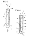
- FIGS. 3 and 4 show the preferred embodiment of the present invention, assembly 30 .
- Assembly 30 comprises an inner tube 40 and outer tube 10a .
- inner tube 40 includes a cylindrical sidewall 42 extending from an open end portion 44 to a lower closed end portion 46 having a semi-spherical wall 48 and an interior area 49 .
- Open end portion 44 tapers outwardly to a second cylindrical sidewall 50 whereby cylindrical sidewall 42 has a smaller internal and external diameter than second cylindrical sidewall 50 .
- Second cylindrical sidewall 50 includes an outer surface 52 and inner surface 54 .
- Second cylindrical sidewall 50 extends to an annular rim 56 .
- Annular flange 58 provides the tapering connection between cylindrical sidewall 42 and second cylindrical sidewall 50 .
- Annular shoulder 60 defines the underside of annular rim 56 .
- Tube 40 has an outer diameter C of about 13 millimeters, a length D of about 75 millimeters, from the rim to the bottom end, and an internal volume of about 1 to 3 milliliters.
- the internal volume of inner tube 40 is less than the internal volume of outer tube 10a and the external dimensions of inner tube 40 are less than the external dimensions of outer tube 10a .
- Inner tube 40 is inserted into or mated within the interior area 18a of outer tube 10a whereby the outer surface 52 of second cylindrical sidewall 50 provides an interference or frictional fit with inner wall surface 20a of outer tube 10a . While the preferred embodiment of the present invention provides a frictional fit between these two engaging surfaces, it is also contemplated that outer surface 52 could be adhesively bonded to inner wall surface 20a . It is further contemplated that inner tube 40 will be inserted into outer tube 10a so that annular shoulder 60 of inner tube 40 abuts against open end rim 14a of tube 10a .
- assembly 30 may be sealed with cap 60 .
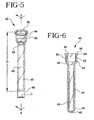
- the assembly of FIG. 7 is evacuated.
- Assembly 30 is provided with a full-draw internal pressure so as to be able to draw a sufficient quantity of blood to substantially fill collection interior area 48.
Landscapes
- Health & Medical Sciences (AREA)
- Chemical & Material Sciences (AREA)
- Analytical Chemistry (AREA)
- General Health & Medical Sciences (AREA)
- Hematology (AREA)
- Clinical Laboratory Science (AREA)
- Chemical Kinetics & Catalysis (AREA)
- Measurement Of The Respiration, Hearing Ability, Form, And Blood Characteristics Of Living Organisms (AREA)
- Sampling And Sample Adjustment (AREA)
- Automatic Analysis And Handling Materials Therefor (AREA)
Claims (8)
- Ensemble formant récipient de prélèvement d'échantillons, comprenant :caractérisé en ce queun tube intérieur allongé (40) possédant une extrémité supérieure ouverte (44), une extrémité inférieure fermée (48), et une première paroi (42) globalement cylindrique définissant, entre elles, un espace intérieur de prélèvement (49), la paroi cylindrique présentant un premier diamètre, l'extrémité supérieure ouverte présentant un épaulement annulaire (60) ;un élément externe (10a) possédant un rebord d'extrémité ouverte (14a), une extrémité fermée (16a) et une paroi cylindrique présentant un deuxième diamètre plus important que le premier diamètre, le tube intérieur allongé (40) étant inséré et fixé dans l'élément externe de telle sorte que l'épaulement annulaire (60) vienne buter contre le rebord d'extrémité ouverte (14a) ;
le tube intérieur allongé est un tube de prélèvement (40) sous vide d'échantillons fermé par un bouchon (60). - Ensemble selon la revendication 1, dans lequel le tube de prélèvement (40) comprend, en outre, une deuxième paroi (50) globalement cylindrique définissant l'extrémité supérieure ouverte (44), la deuxième paroi cylindrique (50) présentant un troisième diamètre plus important que le premier diamètre, et présentant une conicité annulaire établissant la transition, par une bride annulaire (58), entre la première paroi cylindrique et la deuxième paroi cylindrique.
- Ensemble selon la revendication 2, dans lequel la deuxième paroi cylindrique (50) du tube de prélèvement (40) est dimensionnée de tette sorte qu'elle s'insère dans l'élément externe (10a) par un ajustement serré.
- Ensemble selon la revendication 3, dans lequel la deuxième paroi cylindrique (50) du tube de prélèvement (40) est assemblée à l'élément externe (10a) par collage.
- Ensemble selon la revendication 1, dans lequel l'élément externe présente un diamètre d'approximativement 13 millimètres.
- Ensemble selon la revendication 1, dans lequel l'ensemble présente une longueur (D) d'approximativement 75 millimètres.
- Ensemble selon la revendication 1, dans lequel l'espace intérieur de prélèvement présente un volume compris entre approximativement 1 et approximativement 3 millimètres.
- Ensemble selon l'une des revendications 1 à 7, caractérisé par son emploi pour soutirer un fluide dans l'espace intérieur de prélèvement (49) sous vide du tube de prélèvement (40) tandis que le tube de prélèvement est inséré dans l'élément externe (10a).
Applications Claiming Priority (2)
| Application Number | Priority Date | Filing Date | Title |
|---|---|---|---|
| US08/928,350 US5924594A (en) | 1997-09-12 | 1997-09-12 | Collection container assembly |
| US928350 | 1997-09-12 |
Publications (3)
| Publication Number | Publication Date |
|---|---|
| EP0901821A2 EP0901821A2 (fr) | 1999-03-17 |
| EP0901821A3 EP0901821A3 (fr) | 2000-01-12 |
| EP0901821B1 true EP0901821B1 (fr) | 2005-03-30 |
Family
ID=25456125
Family Applications (1)
| Application Number | Title | Priority Date | Filing Date |
|---|---|---|---|
| EP98115764A Expired - Lifetime EP0901821B1 (fr) | 1997-09-12 | 1998-08-21 | Dispositif avec récipient de prélèvement |
Country Status (5)
| Country | Link |
|---|---|
| US (1) | US5924594A (fr) |
| EP (1) | EP0901821B1 (fr) |
| JP (1) | JP4824845B2 (fr) |
| CA (1) | CA2245402C (fr) |
| DE (1) | DE69829531T2 (fr) |
Families Citing this family (25)
| Publication number | Priority date | Publication date | Assignee | Title |
|---|---|---|---|---|
| JP3872893B2 (ja) * | 1997-12-19 | 2007-01-24 | 積水化学工業株式会社 | 真空検体採取管 |
| US6080366A (en) * | 1998-03-02 | 2000-06-27 | Becton, Dickinson And Company | Disposable blood tube holder |
| USD444887S1 (en) | 1999-08-06 | 2001-07-10 | Becton, Dickinson And Company | Stackable tube assembly |
| USD444568S1 (en) | 1999-08-06 | 2001-07-03 | Becton, Dickinson And Company | Stackable tube assembly |
| USD445908S1 (en) | 1999-08-06 | 2001-07-31 | Becton, Dickinson And Company | Stackable tube assembly |
| USD444885S1 (en) | 1999-08-06 | 2001-07-10 | Becton, Dickinson And Company | Stackable tube assembly |
| USD444886S1 (en) | 1999-08-06 | 2001-07-10 | Becton, Dickinson And Company | Stackable tube assembly |
| WO2004022234A2 (fr) * | 2000-07-25 | 2004-03-18 | Becton, Dickinson And Company | Dispositif de recueil |
| US6354452B1 (en) | 2000-07-25 | 2002-03-12 | Becton, Dickinson And Company | Collection container assembly |
| USD448086S1 (en) | 2000-08-24 | 2001-09-18 | Becton Dickinson And Company | Collection tube assembly |
| USD446865S1 (en) | 2000-08-24 | 2001-08-21 | Becton Dickinson And Company | Collection tube assembly |
| USD447812S1 (en) | 2000-08-24 | 2001-09-11 | Becton Dickinson And Company | Collection tube assembly |
| USD448085S1 (en) | 2000-08-24 | 2001-09-18 | Becton Dickinson And Company | Collection tube assembly |
| US20020121139A1 (en) | 2001-03-02 | 2002-09-05 | Purpura Paul E. | Adapter for holding a sample container to facilitate sensing of liquid level in the sample container |
| AU2003273236B2 (en) * | 2002-08-20 | 2010-03-11 | Becton, Dickinson And Company | Collection assembly |
| AU2003268274A1 (en) * | 2002-09-04 | 2004-03-29 | Becton, Dickinson And Company | Collection assembly |
| JP4391761B2 (ja) * | 2003-04-28 | 2009-12-24 | 積水メディカル株式会社 | 血液検査用容器 |
| WO2008031036A1 (fr) * | 2006-09-08 | 2008-03-13 | Becton, Dickinson And Company | Contenant d'échantillon pourvu d'un indicateur de remplissage physique |
| MX339825B (es) * | 2008-10-31 | 2016-06-13 | Biomerieux Inc * | Dispositivo de separacion para su uso en la separacion, caracterizacion y/o identificacion de microorganismos. |
| US8460620B2 (en) * | 2010-12-03 | 2013-06-11 | Becton, Dickinson And Company | Specimen collection container assembly |
| US20150108076A1 (en) * | 2013-10-21 | 2015-04-23 | Health Diagnostic Laboratory, Inc. | Test tube rack insert device |
| WO2018208863A1 (fr) * | 2017-05-08 | 2018-11-15 | Claudia Santamaria | Dispositif de protection d'un récipient interne |
| BR112021003049A2 (pt) * | 2018-08-22 | 2021-05-11 | Quest Diagnostics Investments Llc | placa para aparelho de amostragem e frasco de microcentrífuga para aparelho de microamostragem |
| US11618026B2 (en) * | 2019-03-17 | 2023-04-04 | Michelle Nicole Steiner | False bottom specimen transport tube |
| BE1032752B1 (fr) * | 2024-07-08 | 2026-02-09 | Elysia | Flacon pour echantillon de liquide, ensemble et procede d'acheminement d'echantillon de liquide |
Family Cites Families (21)
| Publication number | Priority date | Publication date | Assignee | Title |
|---|---|---|---|---|
| US3649552A (en) * | 1967-03-31 | 1972-03-14 | Hughes Aircraft Co | Method for preparing high quality rare earth and alkaline earth fluoride single crystals |
| US3807955A (en) * | 1971-04-15 | 1974-04-30 | Becton Dickinson Co | Serum/plasma isolator cup |
| JPS5246778Y2 (fr) * | 1975-01-29 | 1977-10-24 | ||
| GB1533272A (en) * | 1976-02-13 | 1978-11-22 | Radiochemical Centre Ltd | Centrifuge tube |
| JPS5827934B2 (ja) * | 1980-09-25 | 1983-06-13 | テルモ株式会社 | 減圧採血管保持具 |
| US4483616A (en) * | 1981-07-20 | 1984-11-20 | American Hospital Supply Corporation | Container for small quantities of liquids |
| US4578588A (en) * | 1983-08-12 | 1986-03-25 | Galkin Benjamin M | Volume reduction in liquid scintillation counting |
| US5132232A (en) * | 1985-07-30 | 1992-07-21 | V-Tech, Inc. | Method and apparatus for preparation of liquids for examination |
| DE8808738U1 (de) * | 1988-07-07 | 1988-09-01 | Diekmann, Stephan, Dr., 3400 Göttingen | Gefäß zur Druchführung von Reaktionen bei erhöhter Temperatur |
| US4980129A (en) * | 1989-12-22 | 1990-12-25 | Eastman Kodak Company | Kit of collection vessels of uniform outside dimensions, different volumes |
| CA2044422C (fr) * | 1990-07-10 | 1995-02-07 | Hans-Joachim Burkardt | Systeme de transport de prelevements biologiques |
| JP2967364B2 (ja) * | 1990-10-03 | 1999-10-25 | テルモ株式会社 | 採液管 |
| GB9107258D0 (en) * | 1991-04-06 | 1991-05-22 | Chromacol Ltd | Apparatus for use in analytical instruments |
| JPH04347141A (ja) * | 1991-05-23 | 1992-12-02 | Nissho Corp | 微量血液採取装置 |
| US5269927A (en) * | 1991-05-29 | 1993-12-14 | Sherwood Medical Company | Separation device for use in blood collection tubes |
| US5236604A (en) * | 1991-05-29 | 1993-08-17 | Sherwood Medical Company | Serum separation blood collection tube and the method of using thereof |
| FR2688888B1 (fr) * | 1992-03-23 | 1994-07-01 | Boy Sa Inst Jacques | Dispositif destine notamment a la mise en óoeuvre de microtechniques d'analyse. |
| US5780248A (en) * | 1993-07-15 | 1998-07-14 | Ortho Diagnostic Systems, Inc. | Foil sealed cassette for agglutination reactions and liner therefor |
| US5533518A (en) * | 1994-04-22 | 1996-07-09 | Becton, Dickinson And Company | Blood collection assembly including mechanical phase separating insert |
| US5456887A (en) * | 1994-05-27 | 1995-10-10 | Coulter Corporation | Tube adapter |
| JP3634438B2 (ja) * | 1995-04-21 | 2005-03-30 | 積水化学工業株式会社 | 真空採液管 |
-
1997
- 1997-09-12 US US08/928,350 patent/US5924594A/en not_active Expired - Lifetime
-
1998
- 1998-08-20 CA CA002245402A patent/CA2245402C/fr not_active Expired - Fee Related
- 1998-08-21 DE DE69829531T patent/DE69829531T2/de not_active Expired - Lifetime
- 1998-08-21 EP EP98115764A patent/EP0901821B1/fr not_active Expired - Lifetime
- 1998-09-14 JP JP26069098A patent/JP4824845B2/ja not_active Expired - Lifetime
Also Published As
| Publication number | Publication date |
|---|---|
| CA2245402A1 (fr) | 1999-03-12 |
| US5924594A (en) | 1999-07-20 |
| DE69829531D1 (de) | 2005-05-04 |
| EP0901821A3 (fr) | 2000-01-12 |
| DE69829531T2 (de) | 2006-05-04 |
| JPH11151216A (ja) | 1999-06-08 |
| EP0901821A2 (fr) | 1999-03-17 |
| JP4824845B2 (ja) | 2011-11-30 |
| CA2245402C (fr) | 2002-10-22 |
Similar Documents
| Publication | Publication Date | Title |
|---|---|---|
| EP0901821B1 (fr) | Dispositif avec récipient de prélèvement | |
| CA2243899C (fr) | Ensemble recipient de prelevement | |
| US5938621A (en) | Collection container assembly | |
| EP0901817B1 (fr) | Dispositif avec récipient de prélèvement | |
| EP0901818B1 (fr) | Dispositif pour récipient de prélèvement | |
| JP4486690B2 (ja) | 採集容器アッセンブリ | |
| US5975343A (en) | Collection container assembly | |
| WO1984000418A1 (fr) | Recipient pour petites quantites de liquides | |
| EP0901822A2 (fr) | Dispositif avec récipient de prélèvement | |
| MXPA98006919A (en) | Container unit for recolecc |
Legal Events
| Date | Code | Title | Description |
|---|---|---|---|
| PUAI | Public reference made under article 153(3) epc to a published international application that has entered the european phase |
Free format text: ORIGINAL CODE: 0009012 |
|
| AK | Designated contracting states |
Kind code of ref document: A2 Designated state(s): DE FR GB IT |
|
| AX | Request for extension of the european patent |
Free format text: AL;LT;LV;MK;RO;SI |
|
| PUAL | Search report despatched |
Free format text: ORIGINAL CODE: 0009013 |
|
| AK | Designated contracting states |
Kind code of ref document: A3 Designated state(s): AT BE CH CY DE DK ES FI FR GB GR IE IT LI LU MC NL PT SE |
|
| AX | Request for extension of the european patent |
Free format text: AL;LT;LV;MK;RO;SI |
|
| 17P | Request for examination filed |
Effective date: 20000610 |
|
| AKX | Designation fees paid |
Free format text: DE FR GB IT |
|
| 17Q | First examination report despatched |
Effective date: 20030923 |
|
| GRAP | Despatch of communication of intention to grant a patent |
Free format text: ORIGINAL CODE: EPIDOSNIGR1 |
|
| GRAS | Grant fee paid |
Free format text: ORIGINAL CODE: EPIDOSNIGR3 |
|
| GRAA | (expected) grant |
Free format text: ORIGINAL CODE: 0009210 |
|
| AK | Designated contracting states |
Kind code of ref document: B1 Designated state(s): DE FR GB IT |
|
| REG | Reference to a national code |
Ref country code: GB Ref legal event code: FG4D |
|
| RIC1 | Information provided on ipc code assigned before grant |
Ipc: 7A 61B 5/145 B Ipc: 7B 01L 3/14 A |
|
| REF | Corresponds to: |
Ref document number: 69829531 Country of ref document: DE Date of ref document: 20050504 Kind code of ref document: P |
|
| PLBE | No opposition filed within time limit |
Free format text: ORIGINAL CODE: 0009261 |
|
| STAA | Information on the status of an ep patent application or granted ep patent |
Free format text: STATUS: NO OPPOSITION FILED WITHIN TIME LIMIT |
|
| ET | Fr: translation filed | ||
| 26N | No opposition filed |
Effective date: 20060102 |
|
| PGFP | Annual fee paid to national office [announced via postgrant information from national office to epo] |
Ref country code: IT Payment date: 20060831 Year of fee payment: 9 |
|
| PG25 | Lapsed in a contracting state [announced via postgrant information from national office to epo] |
Ref country code: IT Free format text: LAPSE BECAUSE OF NON-PAYMENT OF DUE FEES Effective date: 20070821 |
|
| REG | Reference to a national code |
Ref country code: FR Ref legal event code: PLFP Year of fee payment: 19 |
|
| REG | Reference to a national code |
Ref country code: FR Ref legal event code: PLFP Year of fee payment: 20 |
|
| PGFP | Annual fee paid to national office [announced via postgrant information from national office to epo] |
Ref country code: GB Payment date: 20170719 Year of fee payment: 20 Ref country code: FR Payment date: 20170720 Year of fee payment: 20 Ref country code: DE Payment date: 20170719 Year of fee payment: 20 |
|
| REG | Reference to a national code |
Ref country code: DE Ref legal event code: R071 Ref document number: 69829531 Country of ref document: DE |
|
| REG | Reference to a national code |
Ref country code: GB Ref legal event code: PE20 Expiry date: 20180820 |
|
| PG25 | Lapsed in a contracting state [announced via postgrant information from national office to epo] |
Ref country code: GB Free format text: LAPSE BECAUSE OF EXPIRATION OF PROTECTION Effective date: 20180820 |