EP0901844A2 - Verfahren und Vorrichtung zur Behandlung einer unreinen Flüssigkeit - Google Patents
Verfahren und Vorrichtung zur Behandlung einer unreinen Flüssigkeit Download PDFInfo
- Publication number
- EP0901844A2 EP0901844A2 EP98307346A EP98307346A EP0901844A2 EP 0901844 A2 EP0901844 A2 EP 0901844A2 EP 98307346 A EP98307346 A EP 98307346A EP 98307346 A EP98307346 A EP 98307346A EP 0901844 A2 EP0901844 A2 EP 0901844A2
- Authority
- EP
- European Patent Office
- Prior art keywords
- reagent
- mass transfer
- transfer device
- liquid
- housing
- Prior art date
- Legal status (The legal status is an assumption and is not a legal conclusion. Google has not performed a legal analysis and makes no representation as to the accuracy of the status listed.)
- Withdrawn
Links
- 239000007788 liquid Substances 0.000 title claims abstract description 56
- 238000000034 method Methods 0.000 title claims abstract description 11
- 239000003153 chemical reaction reagent Substances 0.000 claims abstract description 37
- 239000012535 impurity Substances 0.000 claims abstract description 9
- 238000006243 chemical reaction Methods 0.000 claims abstract description 7
- 230000002708 enhancing effect Effects 0.000 claims abstract description 6
- XLYOFNOQVPJJNP-UHFFFAOYSA-N water Substances O XLYOFNOQVPJJNP-UHFFFAOYSA-N 0.000 claims description 43
- 239000002689 soil Substances 0.000 claims description 26
- 239000011159 matrix material Substances 0.000 claims description 22
- 239000000356 contaminant Substances 0.000 claims description 8
- 230000014759 maintenance of location Effects 0.000 claims description 7
- VYPSYNLAJGMNEJ-UHFFFAOYSA-N Silicium dioxide Chemical compound O=[Si]=O VYPSYNLAJGMNEJ-UHFFFAOYSA-N 0.000 claims description 6
- 238000007599 discharging Methods 0.000 claims description 6
- 230000000694 effects Effects 0.000 claims description 5
- 238000001914 filtration Methods 0.000 claims description 5
- 230000003197 catalytic effect Effects 0.000 claims description 4
- 239000000463 material Substances 0.000 claims description 4
- 230000002401 inhibitory effect Effects 0.000 claims description 3
- 229910052751 metal Inorganic materials 0.000 claims description 3
- 239000002184 metal Substances 0.000 claims description 3
- -1 platinum group metals Chemical class 0.000 claims description 3
- 238000006555 catalytic reaction Methods 0.000 claims description 2
- 239000004576 sand Substances 0.000 claims description 2
- 239000000377 silicon dioxide Substances 0.000 claims description 2
- 238000011144 upstream manufacturing Methods 0.000 claims description 2
- CBENFWSGALASAD-UHFFFAOYSA-N Ozone Chemical compound [O-][O+]=O CBENFWSGALASAD-UHFFFAOYSA-N 0.000 description 14
- 230000003647 oxidation Effects 0.000 description 10
- 238000007254 oxidation reaction Methods 0.000 description 10
- 239000007800 oxidant agent Substances 0.000 description 9
- OKTJSMMVPCPJKN-UHFFFAOYSA-N Carbon Chemical compound [C] OKTJSMMVPCPJKN-UHFFFAOYSA-N 0.000 description 8
- 230000001590 oxidative effect Effects 0.000 description 8
- 238000012856 packing Methods 0.000 description 8
- MHAJPDPJQMAIIY-UHFFFAOYSA-N Hydrogen peroxide Chemical compound OO MHAJPDPJQMAIIY-UHFFFAOYSA-N 0.000 description 6
- 239000007789 gas Substances 0.000 description 5
- UFHFLCQGNIYNRP-UHFFFAOYSA-N Hydrogen Chemical compound [H][H] UFHFLCQGNIYNRP-UHFFFAOYSA-N 0.000 description 3
- 239000003638 chemical reducing agent Substances 0.000 description 3
- 229910052739 hydrogen Inorganic materials 0.000 description 3
- 239000001257 hydrogen Substances 0.000 description 3
- 230000001580 bacterial effect Effects 0.000 description 2
- 230000015556 catabolic process Effects 0.000 description 2
- 238000011109 contamination Methods 0.000 description 2
- GNTDGMZSJNCJKK-UHFFFAOYSA-N divanadium pentaoxide Chemical compound O=[V](=O)O[V](=O)=O GNTDGMZSJNCJKK-UHFFFAOYSA-N 0.000 description 2
- 239000003673 groundwater Substances 0.000 description 2
- 238000002386 leaching Methods 0.000 description 2
- 230000008569 process Effects 0.000 description 2
- 230000009467 reduction Effects 0.000 description 2
- 238000005406 washing Methods 0.000 description 2
- 230000009471 action Effects 0.000 description 1
- 150000001338 aliphatic hydrocarbons Chemical class 0.000 description 1
- 230000008901 benefit Effects 0.000 description 1
- 239000006227 byproduct Substances 0.000 description 1
- 239000004568 cement Substances 0.000 description 1
- 230000003247 decreasing effect Effects 0.000 description 1
- 230000001419 dependent effect Effects 0.000 description 1
- 229930195733 hydrocarbon Natural products 0.000 description 1
- 150000002430 hydrocarbons Chemical class 0.000 description 1
- TUJKJAMUKRIRHC-UHFFFAOYSA-N hydroxyl Chemical compound [OH] TUJKJAMUKRIRHC-UHFFFAOYSA-N 0.000 description 1
- 239000003295 industrial effluent Substances 0.000 description 1
- 150000002739 metals Chemical class 0.000 description 1
- 230000035699 permeability Effects 0.000 description 1
- 238000005067 remediation Methods 0.000 description 1
- 239000011347 resin Substances 0.000 description 1
- 229920005989 resin Polymers 0.000 description 1
- 239000002002 slurry Substances 0.000 description 1
- 230000004936 stimulating effect Effects 0.000 description 1
Images

Classifications
-
- B—PERFORMING OPERATIONS; TRANSPORTING
- B09—DISPOSAL OF SOLID WASTE; RECLAMATION OF CONTAMINATED SOIL
- B09C—RECLAMATION OF CONTAMINATED SOIL
- B09C1/00—Reclamation of contaminated soil
- B09C1/002—Reclamation of contaminated soil involving in-situ ground water treatment
-
- B—PERFORMING OPERATIONS; TRANSPORTING
- B01—PHYSICAL OR CHEMICAL PROCESSES OR APPARATUS IN GENERAL
- B01F—MIXING, e.g. DISSOLVING, EMULSIFYING OR DISPERSING
- B01F23/00—Mixing according to the phases to be mixed, e.g. dispersing or emulsifying
- B01F23/20—Mixing gases with liquids
- B01F23/23—Mixing gases with liquids by introducing gases into liquid media, e.g. for producing aerated liquids
- B01F23/231—Mixing gases with liquids by introducing gases into liquid media, e.g. for producing aerated liquids by bubbling
- B01F23/23105—Arrangement or manipulation of the gas bubbling devices
- B01F23/2312—Diffusers
- B01F23/23123—Diffusers consisting of rigid porous or perforated material
-
- B—PERFORMING OPERATIONS; TRANSPORTING
- B01—PHYSICAL OR CHEMICAL PROCESSES OR APPARATUS IN GENERAL
- B01F—MIXING, e.g. DISSOLVING, EMULSIFYING OR DISPERSING
- B01F23/00—Mixing according to the phases to be mixed, e.g. dispersing or emulsifying
- B01F23/20—Mixing gases with liquids
- B01F23/23—Mixing gases with liquids by introducing gases into liquid media, e.g. for producing aerated liquids
- B01F23/233—Mixing gases with liquids by introducing gases into liquid media, e.g. for producing aerated liquids using driven stirrers with completely immersed stirring elements
-
- B—PERFORMING OPERATIONS; TRANSPORTING
- B01—PHYSICAL OR CHEMICAL PROCESSES OR APPARATUS IN GENERAL
- B01F—MIXING, e.g. DISSOLVING, EMULSIFYING OR DISPERSING
- B01F23/00—Mixing according to the phases to be mixed, e.g. dispersing or emulsifying
- B01F23/20—Mixing gases with liquids
- B01F23/23—Mixing gases with liquids by introducing gases into liquid media, e.g. for producing aerated liquids
- B01F23/237—Mixing gases with liquids by introducing gases into liquid media, e.g. for producing aerated liquids characterised by the physical or chemical properties of gases or vapours introduced in the liquid media
- B01F23/2376—Mixing gases with liquids by introducing gases into liquid media, e.g. for producing aerated liquids characterised by the physical or chemical properties of gases or vapours introduced in the liquid media characterised by the gas being introduced
- B01F23/23761—Aerating, i.e. introducing oxygen containing gas in liquids
-
- B—PERFORMING OPERATIONS; TRANSPORTING
- B01—PHYSICAL OR CHEMICAL PROCESSES OR APPARATUS IN GENERAL
- B01F—MIXING, e.g. DISSOLVING, EMULSIFYING OR DISPERSING
- B01F27/00—Mixers with rotary stirring devices in fixed receptacles; Kneaders
- B01F27/80—Mixers with rotary stirring devices in fixed receptacles; Kneaders with stirrers rotating about a substantially vertical axis
- B01F27/91—Mixers with rotary stirring devices in fixed receptacles; Kneaders with stirrers rotating about a substantially vertical axis with propellers
-
- B—PERFORMING OPERATIONS; TRANSPORTING
- B01—PHYSICAL OR CHEMICAL PROCESSES OR APPARATUS IN GENERAL
- B01F—MIXING, e.g. DISSOLVING, EMULSIFYING OR DISPERSING
- B01F2101/00—Mixing characterised by the nature of the mixed materials or by the application field
- B01F2101/305—Treatment of water, waste water or sewage
-
- B—PERFORMING OPERATIONS; TRANSPORTING
- B01—PHYSICAL OR CHEMICAL PROCESSES OR APPARATUS IN GENERAL
- B01F—MIXING, e.g. DISSOLVING, EMULSIFYING OR DISPERSING
- B01F23/00—Mixing according to the phases to be mixed, e.g. dispersing or emulsifying
- B01F23/20—Mixing gases with liquids
- B01F23/23—Mixing gases with liquids by introducing gases into liquid media, e.g. for producing aerated liquids
- B01F23/231—Mixing gases with liquids by introducing gases into liquid media, e.g. for producing aerated liquids by bubbling
- B01F23/23105—Arrangement or manipulation of the gas bubbling devices
- B01F23/2312—Diffusers
- B01F23/23126—Diffusers characterised by the shape of the diffuser element
- B01F23/231265—Diffusers characterised by the shape of the diffuser element being tubes, tubular elements, cylindrical elements or set of tubes
Definitions
- THIS INVENTION relates to the treatment of liquids. More particularly, the invention relates to a mass transfer device for use in the treatment of an impure liquid, a method of treating an impure liquid. equipment for treating an impure liquid and a component for a borehole for use in the treatment of impure liquids.
- a mass transfer device for use in the treatment of an impure liquid, the mass transfer device including
- the side wall may be foraminous having openings which are defined in the side wall for allowing flow of the liquid and the reagent from and back into the housing.
- the reagent may be gaseous with the openings in the side wall being dimensioned according to physical and dynamic parameters of the device and providing the required resistance to movement through them when the liquid and the reagent are expelled from the housing through the openings.
- each impeller blade may have an edge portion which complements the shape of the interior surface of the side wall. At least the tip of the or each impeller blades may be formed of a catalytic material for enhancing catalytic reaction between the impurities in the liquid and the reagent.
- the catalytic material may be selected from the group comprising platinum group metals and may be vanadiumpentoxide.
- the method may include the step of discharging treated water into a soil matrix.
- the method may further include introducing excess reagent into the mass transfer device to enable residual reagent to be entrained in the treated water; and discharging the treated water with the residual reagent through outlet openings of discharge tubes into the soil matrix to effect reaction of contaminants in the soil matrix with the residual reagent.
- the treated water is discharged into the soil matrix to effect oxidation of absorbed organic contaminants in the soil matrix effecting soil washing and leaching and stimulating bacterial activity for further breakdown of adsorbed and absorbed soil contamination.
- equipment for treating an impure liquid including
- the reagent may be in the in the form of an oxidant or a reducing agent.
- the oxidant may be a gaseous oxidant.
- the oxidant may be ozone.
- the reagent supply means may be an ozone generator which, in use, is mounted above ground surface level or an ozonator installed underground.
- the reducing agent may be in the form of hydrogen.
- the equipment may include a retention means arranged within the vessel upstream from the, or a top mass transfer device, for absorbtion of impurities which are contained in treated water which issues from the mass transfer device.
- the retention means may be arranged between an upper water impervious packer and a lower water impervious packer.
- the retention means may comprise a packing of activated carbon, zeolyte, resin, or the like carried in the borehole casing between the lower packing element and the upper packing element.
- the retention means may serve to enhance oxidation or reduction of complex organic hydrocarbons present in the liquid.
- the vessel may be in the form of a borehole casing sunk into a soil matrix.
- the equipment may include a pump for drawing contaminated liquid to be treated into an interior of the borehole casing at an operatively lower elevation of the borehole casing.
- the borehole casing is of such a length that a lower end of the borehole casing will lie below a surface of the subterranean water, i.e. below the surface of the water table.
- the borehole casing may include openings arranged about its circumference via which the water can enter the borehole casing.
- only a lower region of the borehole carries the openings.
- a filtering means may be arranged about an outer periphery of the lower region of the borehole for inhibiting the ingress of detritus into the borehole casing.
- the filtering means may be in the form of a gravel pack including graded silica sand.
- the equipment may also include a drive means which, in use, drives both the pump and the impeller assembly of the mass transfer device.
- the drive means may be an electric motor.
- the equipment may further include a discharge means for discharging treated liquid from the vessel.
- the discharge means may include a discharge conduit comprising a plurality of discharge tubes extending radially outwardly from the discharge end of the vessel and having at least one outlet opening which extends into a soil matrix.
- the discharge means may be arranged below the surface of the ground, at various depths, defined by the hydraulic behaviour of the soil matrix and the yield of the borehole.
- An annular betonite or cement slurry seal may be located between the vessel and the soil matrix to inhibit flow of treated liquid back into the vessel.
- the vessel may alternatively be in the form of a free standing vessel which is used at ground surface level.
- a component for a borehole for use in the treatment of impure liquids including a borehole casing, only an operatively lower region of which is screened.
- impure liquid includes subterranean contaminated liquids such as water containing industrial effluents and/or metals and hydrocarbon-contaminated water, unless the context clearly indicates otherwise.
- screened means, unless the context clearly indicates otherwise, openings defined in the casing.
- the equipment 10 comprises a vessel 12 in the form of a borehole casing sunk into a soil matrix 14.
- the equipment 10 includes a borehole pump 16 arranged proximate a lower end 12.1 of the casing 12.
- a motor 18 is mounted below the borehole pump 16 for driving the pump 16, in use.
- a mass transfer device 20 is mounted intermediate the pump 16 and the motor 18.
- Water pumped by the pump 16 is drawn in from the matrix 14 into an interior 22 of the casing 12 and is then discharged into part 42 of the interior 22 via a feed pipe 24.
- the feed pipe 24 opens out through a lower packer 26 and an upper packer 28 is arranged in vertically spaced relationship proximate a discharge end 12.2 of the borehole casing 12.
- the equipment 10 includes a supply of oxidant in the form of an ozone generator 30 which is mounted above ground level 32.
- the ozone generator supplies ozone via a feed conduit 34 to the mass transfer device 20.
- a second oxidant can be fed into the mass transfer device 20 via a second feed conduit 36 (figure 3).
- the second oxidant can be hydrogen peroxide which creates an hydroxyl radical.
- the borehole casing 12. in the region 37 below the lower packer 26, is screened, i.e. has a plurality of openings 38 defined therein via which water to be treated is drawn into the interior of the borehole casing 12.
- a filtering medium in the form of a gravel pack 40 is arranged around said lower region 37 of the borehole casing 12 for inhibiting the ingress of detritus into the interior 22 of the borehoie casing 12. It is required that only the lower region of the borehole casing 12 is screened rather than the entire casing so that flow of liquid is directed towards the said lower region 37 and into the openings 38.
- the equipment 10 includes a discharge conduit 46 arranged at the discharge end 12.2 of the borehole casing 12 below ground surface level 32.
- the discharge conduit 46 comprises a plurality of discharge tubes 48 projecting radially outwardly from the discharge end 12.2 of the borehole casing 12.
- Each discharge tube 48 has a plurality of outlet openings 50 through which treated water is discharged into the soil matrix 14, as will be described in greater detail below.
- An annular region between the casing 12 and the outlet openings 50 may be sealed off to inhibit flow of treated water back into the casing 12.
- Water from the borehole casing is fed to the discharge conduit 46 via a feed pipe 52 extending through the upper packing element 28.
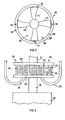
- the mass transfer device 20 comprises a housing 54 having an upper cover 56 and a lower cover 58 arranged on opposed sides of an annular side wall 60.
- the side wall 60 is foraminous having a plurality of apertures 62 defined therein.
- the upper cover 56 is omitted from Figure 2 for the sake of clarity.
- An impeller assembly 64 is rotatably mounted within an interior 66 of the housing 54.
- the impeller assembly 64 comprises a central boss 68 which is mounted rotatably fast with an output shaft 70 from the motor 18.
- a further drive shaft 72 drives the pump 16.
- a plurality of impellers 74 project radially outwardly from the boss 68. Each impeller 74 flares outwardly towards its rip 76 and is curved, as illustrated. Each tip 76 terminates with limited clearance short of an inner surface of the side wall 60. Typically, the clearance between the tip 76 and the side wall 60 is in the order of 1 to 3 mm or less. Further, a flat surface of the tip 76 is shaped to impart shear forces to gas bubbles generated and to create a negative or low pressure region at the trailing edge of the tip 76. This arrangement encourages highly effective contact of the oxidant and the liquid, in addition, facilitates high mass transfer rates between the ozone and the liquid. and hence, the oxidation rate. The expulsion of gas bubbles through the openings 62 in the side wall 60 of the housing 54 and, in addition, facilitates high mass transfer rates between the ozone and the liquid and, hence, ultimately the oxidation rate.
- the device 10 is intended particularly for use for treating halogenated aliphatic hydrocarbon contaminated water. Such water percolates into the soil matrix 14 and into a water table to cause pollution of the ground water.
- the contaminated water is drawn into the interior of the casing 22 by the pump 16.
- ozone from the ozone generator 30 is injected into the mass transfer device 20 via the feed conduit 34.
- hydrogen peroxide from a source (not shown) is injected into the mass transfer device 20 via the feed conduit 36.
- the impellers 74 rotate and ozone gas, in the interior 66 of the mass transfer device reacts with the contaminants in the water to cause oxidation of the contaminants to harmless by-products. Most of the oxidation occurs within the mass transfer device 20 and this oxidation is enhanced due to the shape and configuration of the impeller blades 74 of the impeller assembly 64. Those bubbles which collect on the impellers 74 are driven by centrifugal force to the impeller tips 76 where they are "squeezed" by the impeller tips 76 imparting shear forces thereto to be expelled through the openings 62 in the side wall 60 of the housing 54. The creation of the low pressure region at the trailing edge of the impeller tip 76 encourages re-introduction, by a suction action, of these gas bubbles into the low pressure region to enhance mass transfer and, as a result the oxidation rate.
- the treated water is then pumped by the pump 16 into the part 42 of the interior 22 of the borehole casing 12 where, if the part 42 contains activated carbon, the oxidation process is enhanced.
- the treated water When the treated water reaches the upper packer 28 it is discharged into the discharge tubes 48 of the discharge conduit 46. The water is discharged through the outlet openings 50 of the discharge conduits 48 into the soil matrix 14 to percolate through the soil matrix.
- the number and size of the discharge conduits 48 will be dependent on the radius of influence of the borehole, the soil permeability and hydraulic parameters.
- the equipment 10 may be operated by introducing excess ozone into the mass transfer device 20.
- This excess ozone is entrained in the treated water as it is pumped through the interior 22 of the borehole.
- the treated water when it is discharged through the outlet opening contains residual ozone and, where utilized, hydrogen peroxide with the resultant hydroxyl radicals.
- This treated water, together with the residual oxidants further oxidises absorbed or organic contaminants in the soil matrix 14 to effect soil washing and leaching and stimulate bacterial activity for further breakdown of adsorbed and adsorbed soil contamination.
- the ozone generator may be replaced with a supply of a reducing agent in the form of hydrogen. Hydrogen is thus pumped into the mass transfer device to effect reduction of the contaminants in the water.
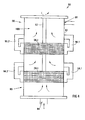
- the equipment 80 comprises a vessel 82 which is positioned at ground level. It will be appreciated that the vessel 82 could also be positioned in a borehole.
- a first and a second mass transfer device 20.1 and 20.2 are mounted inside the vessel 82.
- An inlet 84 is defined at a bottom end 86 of the vessel 82 and an outlet 88 leads from a top end 90 of the vessel 82.
- the mass transfer devices 20.1 and 20.2 are interconnected by means of a central shaft 92 which is in use driven by an electrical motor mounted outside the vessel 82 (not shown).
- Flow pipes 94.1 and 94.2 lead from the first mass transfer device 20.1 to an interior region 96 of the vessel 82 and flow pipes 98.1 and 98.2 lead from the second mass transfer device 20.2 to an interior region 100 the vessel 82.
- impure water is pumped into the vessel 82 via the inlet 84 and is drawn into the mass transfer device 20.1 for treatment as described in Figures 1, 2 and 3.
- flow of water which emanates from the first mass transfer device 20,1 is redirected into the region 96 via the flow pipes 94.1 and 94.2 and then into the second mass transfer device 20.2 for further treatment. Water emanating from the second mass transfer device 20.2 is recirculated into the region 100 and is discharged through the outlet 88.
- mass transfer devices 12 may be used inside the vessel 82.
- the liquid may then be treated further in at least one further mass transfer device to enhance the treatment of the water.
Landscapes
- Chemical & Material Sciences (AREA)
- Chemical Kinetics & Catalysis (AREA)
- Life Sciences & Earth Sciences (AREA)
- Engineering & Computer Science (AREA)
- Hydrology & Water Resources (AREA)
- Water Supply & Treatment (AREA)
- Soil Sciences (AREA)
- Environmental & Geological Engineering (AREA)
- Processing Of Solid Wastes (AREA)
- Physical Or Chemical Processes And Apparatus (AREA)
- Treatment Of Water By Oxidation Or Reduction (AREA)
Applications Claiming Priority (2)
| Application Number | Priority Date | Filing Date | Title |
|---|---|---|---|
| ZA978149 | 1997-09-10 | ||
| ZA9708149 | 1997-09-10 |
Publications (2)
| Publication Number | Publication Date |
|---|---|
| EP0901844A2 true EP0901844A2 (de) | 1999-03-17 |
| EP0901844A3 EP0901844A3 (de) | 2000-11-15 |
Family
ID=25586581
Family Applications (1)
| Application Number | Title | Priority Date | Filing Date |
|---|---|---|---|
| EP98307346A Withdrawn EP0901844A3 (de) | 1997-09-10 | 1998-09-09 | Verfahren und Vorrichtung zur Behandlung einer unreinen Flüssigkeit |
Country Status (2)
| Country | Link |
|---|---|
| US (1) | US6224757B1 (de) |
| EP (1) | EP0901844A3 (de) |
Cited By (2)
| Publication number | Priority date | Publication date | Assignee | Title |
|---|---|---|---|---|
| WO2001044125A1 (en) * | 1999-12-17 | 2001-06-21 | H2O Technologies, Ltd. | Decontamination method and system, such as an in-situ groundwater decontamination system, producing dissolved oxygen and reactive initiators |
| CN102102507B (zh) * | 2009-12-22 | 2014-11-05 | 李建利 | 双腔砂气锚 |
Families Citing this family (6)
| Publication number | Priority date | Publication date | Assignee | Title |
|---|---|---|---|---|
| US20070243037A1 (en) * | 2006-02-28 | 2007-10-18 | Pratt John D | Blind bolt fastener |
| WO2009128916A1 (en) * | 2008-04-14 | 2009-10-22 | Applied Process Technology, Inc. | In situ process and method for ground water remediation and recovery of minerals and hydrocarbons |
| US10233607B2 (en) * | 2017-02-12 | 2019-03-19 | Bahman Niroumand | Comprehensive excavation process |
| DE102017008628A1 (de) * | 2017-09-14 | 2019-03-14 | Julius Montz Gmbh | Stoffaustauschmaschine |
| CN112705561B (zh) * | 2019-10-24 | 2022-05-10 | 中国石油天然气股份有限公司 | 用于污染场地原位修复的自动旋喷注入钻具 |
| US20230364660A1 (en) * | 2022-05-13 | 2023-11-16 | Regenesis Bioremediation Products | Control of soil contaminant mass discharge with horizontal permeable colloidal sorbent barriers |
Family Cites Families (11)
| Publication number | Priority date | Publication date | Assignee | Title |
|---|---|---|---|---|
| DE1140014B (de) * | 1961-03-27 | 1962-11-22 | Johann Grassl | Wasserbelueftungsgeraet |
| SU899051A1 (ru) * | 1980-06-13 | 1982-01-23 | Гродненское Производственное Объединение "Азот" Им. С.О.Притыцкого | Пр моточное контактное устройство |
| DE3931011A1 (de) * | 1989-09-16 | 1991-03-28 | Ieg Ind Engineering Gmbh | Anordnung zum reinigen von verschmutzten filtern in brunnen zur grundwasserreinigung |
| US5520818A (en) * | 1989-12-06 | 1996-05-28 | The University Of Toronto Innovations Foundation | Method for effecting gas-liquid contact |
| FR2672230B1 (fr) * | 1991-02-04 | 1993-04-16 | Anjou Rech | Installation de melange de deux phases fluides par agitation mecanique, notamment pour le traitement des eaux par transfert de gaz oxydant, et utilisation d'une telle installation. |
| US5180503A (en) * | 1991-05-10 | 1993-01-19 | The Board Of Trustees Of The Leland Stanford Junior University | In-situ vapor stripping for removing volatile organic compounds from groundwater |
| US5248613A (en) * | 1991-07-08 | 1993-09-28 | Roubicek Rudolf V | Nonhomogeneous centrifugal film bioreactor |
| DE4138414C2 (de) * | 1991-11-22 | 1993-10-07 | Ieg Ind Engineering Gmbh | Anordnung zum Reinigen von verunreinigtem Grundwasser |
| DE4204059C2 (de) * | 1992-02-07 | 1994-05-05 | Koester Hans Herbert Dipl Geol | Sanierungsbrunnen zur Beseitigung von Grundwasserverunreinigungen |
| US5688076A (en) * | 1996-09-09 | 1997-11-18 | Atkins; Parker E. | High-vacuum groundwater and soil remediation system and related method and apparatus |
| US5849201A (en) * | 1997-06-02 | 1998-12-15 | Mva Inc. | Oxidation of aromatic hydrocarbons |
-
1998
- 1998-09-09 EP EP98307346A patent/EP0901844A3/de not_active Withdrawn
- 1998-09-09 US US09/149,980 patent/US6224757B1/en not_active Expired - Fee Related
Cited By (3)
| Publication number | Priority date | Publication date | Assignee | Title |
|---|---|---|---|---|
| WO2001044125A1 (en) * | 1999-12-17 | 2001-06-21 | H2O Technologies, Ltd. | Decontamination method and system, such as an in-situ groundwater decontamination system, producing dissolved oxygen and reactive initiators |
| US6332972B1 (en) | 1999-12-17 | 2001-12-25 | H20 Technologies, Ltd. | Decontamination method and system, such as an in-situ groundwater decontamination system, producing dissolved oxygen and reactive initiators |
| CN102102507B (zh) * | 2009-12-22 | 2014-11-05 | 李建利 | 双腔砂气锚 |
Also Published As
| Publication number | Publication date |
|---|---|
| EP0901844A3 (de) | 2000-11-15 |
| US6224757B1 (en) | 2001-05-01 |
Similar Documents
| Publication | Publication Date | Title |
|---|---|---|
| US6533499B2 (en) | Soil and groundwater remediation system | |
| US6283674B1 (en) | In-well air stripping, oxidation, and adsorption | |
| US5984578A (en) | Apparatus and method for in situ removal of contaminants using sonic energy | |
| EP1403221B1 (de) | Wasserreinigungsgerät | |
| US5061119A (en) | Method and apparatus for the remediation of contaminated soils | |
| US5197541A (en) | Apparatus for two phase vacuum extraction of soil contaminants | |
| US3650950A (en) | Material shearing mixer and aerator | |
| US7077208B2 (en) | Method and system for directing fluid flow | |
| US6818136B1 (en) | Groundwater remediation system | |
| US6224757B1 (en) | Treatment of liquids | |
| WO2005077504A1 (en) | Device for in-well aerating of water | |
| CN115259304B (zh) | 一种电化学芬顿循环井系统 | |
| US7007759B2 (en) | Method and system for directing fluid flow | |
| KR101720098B1 (ko) | 휘발성 유기화합물 오염 지하수 정화 장치 | |
| AU6371400A (en) | Decontamination method and system, such as an in-situ groundwater decontamination system, producing dissolved oxygen and reactive initiators | |
| CN116216912A (zh) | 一种地下水有机污染物净化系统及方法 | |
| CN108689480A (zh) | 一种高级污水氧化处理设备 | |
| CN215543670U (zh) | 一种抽吸深度可调节的多相抽提管 | |
| CN218969061U (zh) | 一种污泥发酵协同高浓度有机废水处理装置 | |
| JP2003047952A (ja) | 地下水浄化装置及び地下水浄化方法 | |
| JP4905727B2 (ja) | 有機性排水の処理方法及び装置 | |
| CN207259288U (zh) | 一种餐饮废水处理设备 | |
| CN113830980A (zh) | 一种原位处理河道底泥重金属污染的装置 | |
| CN213771717U (zh) | 一种含油废水处理装置 | |
| CN210048588U (zh) | 一种有机污染土壤修复用废水处理装置 |
Legal Events
| Date | Code | Title | Description |
|---|---|---|---|
| PUAI | Public reference made under article 153(3) epc to a published international application that has entered the european phase |
Free format text: ORIGINAL CODE: 0009012 |
|
| AK | Designated contracting states |
Kind code of ref document: A2 Designated state(s): AT BE CH CY DE DK ES FI FR GB GR IE IT LI LU MC NL PT SE |
|
| AX | Request for extension of the european patent |
Free format text: AL;LT;LV;MK;RO;SI |
|
| PUAL | Search report despatched |
Free format text: ORIGINAL CODE: 0009013 |
|
| AK | Designated contracting states |
Kind code of ref document: A3 Designated state(s): AT BE CH CY DE DK ES FI FR GB GR IE IT LI LU MC NL PT SE |
|
| AX | Request for extension of the european patent |
Free format text: AL;LT;LV;MK;RO;SI |
|
| AKX | Designation fees paid | ||
| REG | Reference to a national code |
Ref country code: DE Ref legal event code: 8566 |
|
| STAA | Information on the status of an ep patent application or granted ep patent |
Free format text: STATUS: THE APPLICATION IS DEEMED TO BE WITHDRAWN |
|
| 18D | Application deemed to be withdrawn |
Effective date: 20010516 |