EP0901853B1 - Coulée sous pression à vide poussé - Google Patents
Coulée sous pression à vide poussé Download PDFInfo
- Publication number
- EP0901853B1 EP0901853B1 EP98115778A EP98115778A EP0901853B1 EP 0901853 B1 EP0901853 B1 EP 0901853B1 EP 98115778 A EP98115778 A EP 98115778A EP 98115778 A EP98115778 A EP 98115778A EP 0901853 B1 EP0901853 B1 EP 0901853B1
- Authority
- EP
- European Patent Office
- Prior art keywords
- alloy
- shot sleeve
- die cavity
- dies
- die
- Prior art date
- Legal status (The legal status is an assumption and is not a legal conclusion. Google has not performed a legal analysis and makes no representation as to the accuracy of the status listed.)
- Expired - Lifetime
Links
- 238000004512 die casting Methods 0.000 title claims description 27
- 239000000956 alloy Substances 0.000 claims description 90
- 229910045601 alloy Inorganic materials 0.000 claims description 89
- 229910052751 metal Inorganic materials 0.000 claims description 73
- 239000002184 metal Substances 0.000 claims description 73
- RTAQQCXQSZGOHL-UHFFFAOYSA-N Titanium Chemical compound [Ti] RTAQQCXQSZGOHL-UHFFFAOYSA-N 0.000 claims description 23
- 239000010936 titanium Substances 0.000 claims description 23
- 229910052719 titanium Inorganic materials 0.000 claims description 23
- PXHVJJICTQNCMI-UHFFFAOYSA-N Nickel Chemical compound [Ni] PXHVJJICTQNCMI-UHFFFAOYSA-N 0.000 claims description 22
- 238000002844 melting Methods 0.000 claims description 20
- 230000008018 melting Effects 0.000 claims description 20
- XEEYBQQBJWHFJM-UHFFFAOYSA-N Iron Chemical compound [Fe] XEEYBQQBJWHFJM-UHFFFAOYSA-N 0.000 claims description 18
- 239000012080 ambient air Substances 0.000 claims description 18
- 239000000155 melt Substances 0.000 claims description 16
- 238000000034 method Methods 0.000 claims description 15
- 238000002347 injection Methods 0.000 claims description 12
- 239000007924 injection Substances 0.000 claims description 12
- 229910052759 nickel Inorganic materials 0.000 claims description 11
- 229910052742 iron Inorganic materials 0.000 claims description 9
- 239000000463 material Substances 0.000 claims description 7
- 229910001220 stainless steel Inorganic materials 0.000 claims description 7
- QVGXLLKOCUKJST-UHFFFAOYSA-N atomic oxygen Chemical group [O] QVGXLLKOCUKJST-UHFFFAOYSA-N 0.000 claims description 5
- 239000001301 oxygen Substances 0.000 claims description 5
- 229910052760 oxygen Inorganic materials 0.000 claims description 5
- 239000010935 stainless steel Substances 0.000 claims description 5
- RYGMFSIKBFXOCR-UHFFFAOYSA-N Copper Chemical compound [Cu] RYGMFSIKBFXOCR-UHFFFAOYSA-N 0.000 claims description 4
- 229910052802 copper Inorganic materials 0.000 claims description 4
- 239000010949 copper Substances 0.000 claims description 4
- 229910001069 Ti alloy Inorganic materials 0.000 claims description 3
- 229910010293 ceramic material Inorganic materials 0.000 claims description 3
- 238000010791 quenching Methods 0.000 claims description 3
- 230000000171 quenching effect Effects 0.000 claims description 3
- 239000011819 refractory material Substances 0.000 claims description 3
- 238000007789 sealing Methods 0.000 claims description 3
- 229910001067 superalloy steel Inorganic materials 0.000 claims 1
- 238000005266 casting Methods 0.000 description 10
- 229910000601 superalloy Inorganic materials 0.000 description 8
- 150000002739 metals Chemical class 0.000 description 6
- 239000007789 gas Substances 0.000 description 5
- 238000001816 cooling Methods 0.000 description 4
- 229910000831 Steel Inorganic materials 0.000 description 3
- 229910000883 Ti6Al4V Inorganic materials 0.000 description 3
- 230000013011 mating Effects 0.000 description 3
- 239000007787 solid Substances 0.000 description 3
- 239000010959 steel Substances 0.000 description 3
- XLYOFNOQVPJJNP-UHFFFAOYSA-N water Substances O XLYOFNOQVPJJNP-UHFFFAOYSA-N 0.000 description 3
- 229910001315 Tool steel Inorganic materials 0.000 description 2
- PNEYBMLMFCGWSK-UHFFFAOYSA-N aluminium oxide Inorganic materials [O-2].[O-2].[O-2].[Al+3].[Al+3] PNEYBMLMFCGWSK-UHFFFAOYSA-N 0.000 description 2
- 239000000919 ceramic Substances 0.000 description 2
- 230000007547 defect Effects 0.000 description 2
- 239000012530 fluid Substances 0.000 description 2
- 230000006698 induction Effects 0.000 description 2
- 238000005495 investment casting Methods 0.000 description 2
- 239000011800 void material Substances 0.000 description 2
- 229910000838 Al alloy Inorganic materials 0.000 description 1
- 229910000851 Alloy steel Inorganic materials 0.000 description 1
- 229910000952 Be alloy Inorganic materials 0.000 description 1
- 229920002449 FKM Polymers 0.000 description 1
- 229910001182 Mo alloy Inorganic materials 0.000 description 1
- -1 Ti-6Al-4V Chemical compound 0.000 description 1
- 229910052782 aluminium Inorganic materials 0.000 description 1
- XAGFODPZIPBFFR-UHFFFAOYSA-N aluminium Chemical compound [Al] XAGFODPZIPBFFR-UHFFFAOYSA-N 0.000 description 1
- 239000010941 cobalt Substances 0.000 description 1
- 229910017052 cobalt Inorganic materials 0.000 description 1
- GUTLYIVDDKVIGB-UHFFFAOYSA-N cobalt atom Chemical compound [Co] GUTLYIVDDKVIGB-UHFFFAOYSA-N 0.000 description 1
- 239000000498 cooling water Substances 0.000 description 1
- 238000010438 heat treatment Methods 0.000 description 1
- 238000004519 manufacturing process Methods 0.000 description 1
- 230000002093 peripheral effect Effects 0.000 description 1
- 238000003825 pressing Methods 0.000 description 1
- 210000003625 skull Anatomy 0.000 description 1
- 230000008961 swelling Effects 0.000 description 1
Images


Classifications
-
- B—PERFORMING OPERATIONS; TRANSPORTING
- B22—CASTING; POWDER METALLURGY
- B22D—CASTING OF METALS; CASTING OF OTHER SUBSTANCES BY THE SAME PROCESSES OR DEVICES
- B22D17/00—Pressure die casting or injection die casting, i.e. casting in which the metal is forced into a mould under high pressure
- B22D17/14—Machines with evacuated die cavity
-
- B—PERFORMING OPERATIONS; TRANSPORTING
- B22—CASTING; POWDER METALLURGY
- B22D—CASTING OF METALS; CASTING OF OTHER SUBSTANCES BY THE SAME PROCESSES OR DEVICES
- B22D17/00—Pressure die casting or injection die casting, i.e. casting in which the metal is forced into a mould under high pressure
- B22D17/20—Accessories: Details
- B22D17/22—Dies; Die plates; Die supports; Cooling equipment for dies; Accessories for loosening and ejecting castings from dies
- B22D17/2272—Sprue channels
- B22D17/2281—Sprue channels closure devices therefor
Definitions
- the present invention relates to die casting of metals and alloys and, more particularly, to vacuum die casting of metals and alloys under relatively high vacuum die cavity conditions.
- Titanium, titanium based alloy, nickel based alloy, and stainless steel castings are used in large numbers in the aerospace industry. Many such castings are made by the well known investment casting process wherein an appropriate melt is cast into a preheated ceramic investment mold formed by the lost wax process. Although widely used, investment casting of complex shaped components of such reactive materials can be characterized by relatively high costs and low yields. Low casting yields are attributable to several factors including surface or surface-connected, void type defects and/or inadequate filling of certain mold cavity regions, especially thin mold cavity regions, and associated internal void, shrinkage and like defects.
- the shot sleeve is provided with an open funnel for pouring melt into the shot sleeve which opens into the mold cavity. When the mold is closed, the mold cavity is not sealed in an air-tight manner.
- the present invention further provides for quenching of the cast components in a quenchant medium proximate the dies.
- one or more high temperature vacuum seals is/are provided between the dies about the die cavity such that a vacuum is provided in the die cavity through the shot sleeve when the vacuum chamber is evacuated.
- the first and second dies are opened after the metal or alloy is die cast in the die cavity followed by removal of the cast component from the die cavity directly to the ambient atmosphere or to an optional quenchant medium proximate the dies.
- the present invention envisions in one embodiment evacuating the die cavity to a vacuum level of less than 33,86 hPas (1000 microns) through the shot sleeve, introducing a reactive molten metal or alloy, such as a titanium, titanium based alloy, nickel based superalloy, and iron based alloy, into the shot sleeve in the vacuum melting chamber preferably in an amount that occupies less than 40 volume %, such as about 8 to about 15 volume %, of the effective internal shot sleeve volume, and then advancing the plunger to inject the reactive molten metal or alloy into the sealed, evacuated die cavity where at least the outer surface of the cast component can solidify before opening of the dies to break the vacuum seal(s) and expose the cast component to ambient air atmosphere for removal from the die and optional quenching in a quenchant medium.
- a reactive molten metal or alloy such as a titanium, titanium based alloy, nickel based superalloy, and iron based alloy
- the present invention envisions in another embodiment placing a plug in the shot sleeve prior to introduction of the metal or alloy located downstream of the shot sleeve melt inlet such that the plug improves filling of the shot sleeve with the proper volume of molten metal or alloy needed to fill the die cavity.
- the plug is advanced toward the die cavity as the plunger pressure injects the molten metal or alloy in the die cavity.
- the plug is moved by advancement of the plunger into a plug-receiving chamber out of the way of the die cavity so as not to interfere with injection of the molten metal or alloy in the die cavity.
- the shot sleeve and the plunger, or optional disposable plunger tip, contacting the molten metal or alloy can be made of an iron based material, such as H-13 tool steel, a refractory material such as Mo based alloy or TZM alloy, ceramic material such as alumina, or combinations thereof.
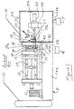
- die casting apparatus in accordance with an embodiment of the present invention is shown for die casting a metal or alloy such as especially titanium and titanium based alloys that are highly reactive with oxygen, under relatively high vacuum conditions in the die cavity despite the dies being disposed exteriorly in ambient air atmopshere.
- the apparatus also can be used to die cast nickel, cobalt base and other superalloys, iron based alloys such as stainless steels, and other metals or alloys under relatively high vacuum conditions in the die cavity.
- the die casting apparatus comprises a base 10 which defines therein a reservoir 10a for hydraulic fluid that is used by hydraulic actuator 12 to open and close the fixed and movable die platens 14, 16.
- the platen 16 is disposed for movement on stationary tie bars or rods 18 and has a die 34 disposed thereon.
- a die clamping linkage mechanism 20 is connected to the movable die platen 16 in conventional manner not considered part of the present invention to open/close the movable die 34 relative to fixed die 32 disposed on platen 14.
- a conventional die casting machine available as 250 ton HPM #73-086 from HPM, Cleveland, Ohio, includes such a base 10, actuator 12, and die platens 14, 16 mounted on tie bars 18 and opened/closed by die clamping linkage mechanism 20 in the manner described.
- the die casting machine includes a gas accumulator 21 for rapid feeding of hydraulic fluid to the plunger mechanism.
- the die casting apparatus comprises a tubular, horizontal shot sleeve 24 that communicates to a die cavity 30 defined by the dies 32, 34 disposed on the respective die platens 14, 16.
- One or more die cavities can be formed by dies 32, 34 to die cast one or more components.
- the shot sleeve 24 has an discharge end section 24a that communicates with the entrance passage or gate 36 to the one or more die cavities 30 so that molten metal or alloy can be pressure injected therein.
- the entrance passage or gate 36 can be machined in the stationary die 32 or the movable die 34, or both.
- the discharge end section 24a of the shot sleeve 24 extends through a suitable passage 24b in the stationary platen 14 and die 32 as illustrated in Figure 1.
- the shot sleeve 24 extends through die 32 into a vacuum melting chamber 40 where the metal or alloy to be die cast is melted under relatively high vacuum conditions such as less than 33,86 hPas (1000 microns) required by titanium and its alloys, such as Ti-6Al-4V, which are highly reactive to oxygen in ambient air at elevated temperatures.
- the vacuum chamber 40 is defined by a vacuum housing wall 42 that extends about and encompasses or surrounds the opposite charging end section of the shot sleeve 24 receiving the plunger 27 and the plunger hydraulic actuator 25.
- the vacuum chamber 40 is evacuated by a conventional vacuum pump P connected to the chamber 40 by a conduit 40a.
- the base 10 and the vacuum housing wall 42 rest on a concrete floor or other suitable support.
- the chamber wall 42 is airtight sealed with the fixed platen 14 by a peripheral airtight seal(s) 43 located therebetween so as to sealingly enclose the shot sleeve 24 and a pair of side-by-side stationary, horizontal shot sleeve/plunger support members 44 (one shown) extending through chamber wall 42.
- shot sleeve/plunger support members are provided on the aforementioned conventional die casting machine (250 ton HPM #73-086).
- a plunger 27 is disposed in the shot sleeve 24 for movement by plunger acutator 25 and plunger connector rod 27b between a start injection position located to the right of a melt entry or inlet opening 58 in shot sleeve 24 and a finish injection position proximate the die entrance gate 36.
- the melt inlet opening 58 communicates to a metal (e.g. steel) melt-receiving vessel 52 mounted adjacent the fixed platen 14 on the shot sleeve 24 by clamps, such as screw clamps (not shown).
- the melt-receiving vessel 52 is disposed beneath a melting crucible 54 to receive a charge of molten metal or alloy therefrom for die casting.
- the melting crucible 54 may be a conventional induction skull crucible comprising copper segements in which a charge of solid metal or alloy to be die cast is charged via vacuum port 40b and melted by energization of induction coils 56 disposed about the crucible in conventional manner in the chamber 40.
- Known ceramic or refractory lined crucibles also can be used in practicing the present invention.
- the crucible 54 can be tilted by rotation about crucible trunnions T using a conventional hydraulic, electrical or other actuator (not shown) disposed outside the vacuum chamber 40 and connected to the crucible by a suitable vacuum sealed linkage extending from the actuator to the crucible.
- the crucible is tilted to pour the molten metal or alloy charge into the melt-receving vessel 52, which is communicated to the shot sleeve 24 via opening 58 in the shot sleeve wall.
- the molten metal or alloy charge is introduced through opening 58 into the shot sleeve 24 in front of the plunger tip 27a.
- the molten metal or alloy charge is introduced into the shot sleeve in an amount that is less than 40 volume % of the effective internal volume of the shot sleeve defined in front of the plunger tip 27a and extending to the entrance or gate 36 of the die cavity.
- the amount of molten metal or alloy occupies less than 20 volume %, and even more preferably from about 8 to about 15 volume %, of the effective internal volume of the shot sleeve.
- Such a relatively low volume of molten charge relative to the shot sleeve internal volume provides a relatively low molten charge profile in the shot sleeve (i.e. the molten charge lies more along the bottom of the shot sleeve) to thereby reduce the contact area and contact time of the high temperature molten charge with the plunger tip 27a and resultant swelling of the plunger tip prior to melt injection into the mold cavity.
- the plunger 27 is moved from the start injection position to the finish injection position by a conventional hydraulic actuator 25 that, for example, is provided on the aforementioned conventional die casting machine (250 ton HPM #73-086).
- Typical plunger speeds are in the range of 15,24 to 91,44 m/s (50 to 300 feet/second).
- Radial clearances between the shot sleeve 24 and the plunger tip 27a are in the range of about 0,0127 to 0,508 mm (0.0005 inch to 0.020 inch).
- a preferred radial clearance between the shot sleeve 24 and the plunger tip 27a is about 0,203 mm (0.008 inch).
- the shot sleeve 24 and forward plunger tip 27a contacting the molten metal or alloy can be made of an iron based material, such as H-13 tool steel, or a refractory material such as based on Mo alloy or TZM alloy, ceramic material such as alumina, or combinations thereof that are compatible with the metal or alloy being melted and die cast.
- the plunger tip 27a can comprise a disposable tip that is thrown away after each molten metal or alloy charge is injected in the die cavity 30.
- a disposable plunger tip can comprise a copper based alloy such as a copper-beryllium alloy (e.g. D340 alloy), which is especially suitable for die casting A380 aluminum alloy.
- the dies 32, 34 can be made of steel and/or titanium pursuant to Colvin U.S. Patent 5 287 910, although other die materials may be used in practicing the invention.
- the first and second dies 32, 34 are disposed outside the vacuum melting chamber 40 in ambient air atmosphere. That is, exterior surfaces or sides of the dies 32, 34 are exposed to ambient air atmosphere.
- the die cavity 30 defined therebetween is communicated to the vacuum chamber 40 via the shot sleeve 24 and can be evacuated through the shot sleeve.
- the stationary die 32 typically includes one or more grooves 32a on its inner face 32b (one groove shown in Figure 2) that mates with the opposing inner face of the movable die 34 when the dies are closed.
- the groove(s) 32a encircle or extend about the die cavity 30 as well as gate 36 and a melt discharge opening commuicated to gate 36 and defined by shot sleeve end 24a.
- the groove 32a receives a resilent, reusable high temperature O-ring vacuum seal 60 for sealing in vacuum tight manner against the mating face of the movable die 34 when the dies are closed.
- the seal(s) 60 can be disposed in grooves on the mating face of the movable die 34, or they can be disposed on the mating faces of both dies 32, 34, so as to form a vacuum tight seal about and isolating the die cavity 30, gate 36 and shot sleeve end 24a from the ambient air atmosphere surrounding the exterior of the dies 32, 34 when closed.
- a series of several grooves and O-ring seals can be provided progressively outwardly relative to the die cavity perimeter to form a plurality of vacuum tight seals.
- the vacuum seals 60 may comprise Viton material that can withstand temperatures as high as 204°C (400 degrees F) that may be present when the die cavity 30 is filled with molten metal or alloy.
- the die cavity 30 is isolated from the ambient air atmosphere when the dies 32, 34 are closed and enables the die cavity 30 to be evacuated through the shot sleeve 24 when the vacuum melting chamber 40 is evacuted to high vacuum levels of less than 33,86 hPas (1000 microns) employed for melting the solid charge in the crucible 54.
- a solid metal or alloy is charged into the crucible 54 in the vaccuum melting chamber 40 via port 40b.
- the vacuum chamber 40 then is evacuated to a suitable level for melting the particular charge (such as less than 3,386 hPas (100 microns); e.g. 3,047 hPas (90 microns), for titanium and its alloys such as Ti-6Al-4V alloy, nickel base. superalloys, and stainless steels) by vacuum pump P.
- the die cavity 30 formed by the closed dies 32, 34 is concurrently evacuated to the same vacuum level through the connection to the vacuum melting chamber 40 via the shot sleeve 24 and by virtue of being isolated from surrounding ambient atmosphere by the vacuum seal(s) 60.
- the molten charge of the metal or alloy in crucible 54 is poured under vacuum into the shot sleeve 24 via the vessel 52 and melt inlet opening 58 with the plunger 27 initially positioned at the start injection position of Figure 1.
- the molten metal or alloy charge is introduced into the shot sleeve in an amount that is less than 40 volume % of the effective internal volume of the shot sleeve.
- the amount of molten metal or alloy occupies less than 20 volume %, and even more preferably from about 8 to about 15 volume %, of the effective internal volume of the shot sleeve.
- the molten metal or alloy is poured into the shot sleeve 24 and resides therein for a preselected dwell time of between 0.005 seconds and 4 seconds, typically only 0.1 second to 1.5 seconds, for the purpose of insuring that no molten metal gets behind the plunger 27.
- the melt can be poured directly from the crucible 54 via vessel 52 into the shot sleeve 24, thereby reducing time and metal cooling before injection can begin.
- the plunger 27 then is advanced in the shot sleeve 24 by actuator 25 to pressure inject the molten metal or alloy into the die cavity 30 via entrance passage or gate 36.
- the molten metal or alloy is forced at high velocities, such as up to 380 cm (150 inches) per second, down the shot sleeve 24 and into sealed, evacuated die cavity 30.
- the dies 32, 34 are opened by movement of die 34 relative to die 32 within a typical time period that can range from 5 to 25 seconds following injection to provide enough time for the molten metal or alloy to form at least a solidified surface on the die cast component(s).
- the dies 32, 34 then are opened to allow ready removal of the die cast component(s) from the dies.
- a conventional .ejector pin mechanism (not shown) provided on the aforementioned HPM die casting machine and not forming a part of the invention helps eject the die cast component(s) from the dies. Removal of the die cast component(s) can be made directly from the dies 32, 34 simply by opening the dies without further cooling of the cast component(s).
- the vacuum seal(s) 60 is/are broken, and the cast component(s) is/are exposed to ambient air atmosphere and optionally can be quenched in a quenchant medium M, such as water, oil and the like, located proximate the open dies 32, 34.
- a quenchant medium M such as water, oil and the like
- the present invention envisions in another embodiment placing a floating plug 70 in a longer shot sleeve 24 prior to introduction of the metal or alloy from crucible 54.
- the plug 70 initially is located downstream of the melt inlet opening 58 to improve filling of the shot sleeve 24 between the plug 70 and the plunger tip 27a with the proper volume of molten metal or alloy needed to fill the die cavity 30.
- the plug 70 is advanced toward the die cavity 30 as the plunger 27 pressure injects the molten metal or alloy in the die cavity 30.
- the plug 70 is moved by advancement of the plunger 27 into a plug-receiving chamber 72 formed in the movable die 34 out of the way of the die cavity entrance passage 36 so as not to interfere with injection of the molten metal or alloy in the die cavity.
- the plug 70 can comprise steel for titanium and its alloys and other high melt temperature metal which is resistant to reaction with the particular molten metal being die cast.
- the plug 70 is dimensioned such that it will stay in place durng sleeve filling with molten metal from the vessel 52 and remain ahead of the injected metal until it rests in chamber 72.
- the temperature of the dies 32, 34 can be controlled within desired ranges to provide die temperatures in the range of 37,8 - 392 °C (100-700 degrees F).
- the dies 32, 34 can be preheated prior to the start of injection of molten metal or alloy therein by one or more conventional gas flame burners or electrical resistance heating wires operably associated with the dies to this end.
- the dies 32, 34 can be cooled by water cooling conduits (not shown) formed internally of the dies and through which cooling water is circulated to control die temperature as die cast components continue to be made and the dies heat up.
- the shot sleeve 24 similarly also optionally can be heated or cooled to control shot sleeve temperature within a desired range such as 37,8 - 392 °C (100-700 degrees F) by similar gas flame burners or electrical resistance wires or water cooling passages in the shot sleeve.
- a charge of molten titanium or an alloy thereof, such as Ti-6Al-4V, comprising from 2,27 - 4,54 Mg (5 to 10 pounds) of melt at a melt temperature typically equal to the metal or alloy melting point plus 28°C (50 degrees F)(e.g. about 1694°C (3080 degrees F) for Ti-6A1-4V) can be introduced into shot sleeve 24 having a length of 41,9 cm (16.5 inches) and diameter of 7,6 cm (3 inches.
- the molten charge occupies about 9-10 volume % of the effective internal volume of shot sleeve 24, which includes therein a copper-berylium plunger tip having a radial clearance of 0,051 mm (0.002 inch) with the shot sleeve.
- the plunger moves at a minimum of 318 cm/s (125 inches per second) to inject the charge into the die cavity defined between the dies 32, 34 which can be preheated to 149°C (300 degrees F).
- Nickel base superalloys can be die cast pursuant to the invention using similar parameters with a melt temperature equal to the alloy melting point plus 42°C (75 degrees F).
- Stainless steel 17-4 PH can be die cast pursuant to the invention using similar parameters with a melt temperature equal to the alloy melting point plus 14°C (25 degrees F).
- the invention can be used to die cast complex shaped or configured components such as gas turbine compressor vanes and blades made of nickel base superalloys, such as for example only IN 718 nickel base superalloy, for the compressor section of a gas turbine engine as well as golf club putters made of stainless steel, such as 17-4 PH stainless steel and amorphous alloys, as well as a wide variety of other components.
- nickel base superalloys such as for example only IN 718 nickel base superalloy
- golf club putters made of stainless steel such as 17-4 PH stainless steel and amorphous alloys, as well as a wide variety of other components.
- the present invention also relates to a method of die casting titanium or an alloy thereof, said method comprising
- the melt is introduced into the shot sleeve in an amount of about 8 to about 15 volume % of the effective internal volume of the shot sleeve.
Landscapes
- Engineering & Computer Science (AREA)
- Mechanical Engineering (AREA)
- Molds, Cores, And Manufacturing Methods Thereof (AREA)
- Moulds For Moulding Plastics Or The Like (AREA)
- Injection Moulding Of Plastics Or The Like (AREA)
Claims (21)
- Appareil de coulée sous pression comprenant :caractérisé en ce que lesdites filières (32, 34) sont disposées dans une atmosphère d'air ambiant et comprennent un joint hermétique (60) entre lesdites filières afin d'isoler ladite cavité de moule (30) de l'atmosphère d'air ambiant quand lesdites filières sont fermées, en ce que les moyens (P, 40a, 40b) destinés à évacuer ladite chambre à dépression (40) sont adaptés pour évacuer simultanément ladite cavité de moule (30) à travers ladite chambre d'injection (24) en vertu du fait que ladite cavité de moule (30) est isolée de l'atmosphère d'air ambiant par ledit joint hermétique (60) et en ce qu'un composant de coulée sous pression est amovible de la cavité de moule (30) directement dans l'atmosphère d'air ambiant.a) une première et une seconde filières (32, 34) qui définissent une cavité de moule (30) entre elles quand les filières sont fermées,b) une chambre d'injection (24) communiquant au niveau d'une extrémité avec la cavité de moule (30) et présentant une autre extrémité avec un orifice d'entrée de coulée (58) communiquant avec un chambre à dépression (40),c) une cuve de fusion (54) disposée dans la chambre à dépression (40) destinée à préparer une coulée d'un métal ou d'un alliage qui est introduit à travers ledit orifice d'entrée de coulée (58) à l'intérieur de ladite chambre d'injection (24) en avant d'un piston plongeur (27) qui est mobile dans ladite chambre d'injection,d) des moyens (P, 40a, 40b) destinés à évacuer la chambre à dépression (40) quand le métal ou l'alliage fondu est fondu dans ladite cuve de fusion,e) ledit piston plongeur (27) étant mobile dans ladite chambre d'injection (24) pour injecter le métal ou l'alliage fondu à l'intérieur de ladite cavité (30), etf) des moyens (20) destinés à ouvrir les filières (32, 34) après que le métal ou l'alliage fondu est injecté à l'intérieur de celles-ci,
- Appareil selon la revendication 1, dans lequel ledit joint hermétique (60) comprend un joint torique sur au moins une filière (32) et s'étendant autour de ladite cavité (30), une porte (36) et une ouverture d'éjection de coulée (24a) communiquant avec ladite porte.
- Appareil selon la revendication 1, dans lequel ladite chambre à dépression (40) et la cavité de moule (30) sont adaptées pour être évacuées à moins de 33,86 hectopascals (1 000 microns).
- Appareil selon la revendication 1, dans lequel l'espace mort radial entre le piston plongeur (27) et la chambre d'injection (24) se situe approximativement entre 0,0127 mm (0,0005 pouce) et 0,508 mm (0,020 pouce).
- Appareil selon la revendication 1, dans lequel ladite cuve de fusion (54) est adaptée pour introduire une charge du métal ou de l'alliage fondu qui occupe moins de 40 % en volume du volume intérieur effectif de la chambre d'injection (24).
- Appareil selon la revendication 5, dans lequel la charge de métal ou d'alliage fondu occupe environ entre 8 % et 15 % en volume du volume intérieur effectif de la chambre d'injection (24).
- Appareil selon la revendication 1 comprenant en outre un bouchon (70) disposé dans ladite chambre d'injection (24) en aval dudit orifice d'entrée de coulée (58), ledit bouchon étant déplacé par le mouvement du piston plongeur (27) à travers ladite chambre d'injection (24) vers ladite cavité de moule (30).
- Appareil selon la revendication 7, dans lequel une desdites filières (32, 34) comprend une chambre (72) destinée à recevoir ledit bouchon (70) quand ledit métal ou alliage fondu est injecté dans ladite cavité de moule (30).
- Appareil selon la revendication 1, dans lequel ladite chambre d'injection (24) et ledit piston plongeur (27) comprennent un matériau sélectionné à partir du groupe consistant en un matériau à base de métal, un matériau réfractaire, un matériau céramique et des combinaisons de ceux-ci.
- Appareil selon la revendication 1, dans lequel ledit piston plongeur (27) comprend une pointe de piston plongeur jetable (27a).
- Appareil selon la revendication 10, dans lequel ladite pointe de piston plongeur (27a) comprend un alliage à base de cuivre.
- Appareil selon la revendication 1 comprenant des moyens destinés à commander la température d'au moins une desdites filières et de ladite chambre d'injection.
- Appareil selon la revendication 1, dans lequel ladite cuve (54) est disposée adjacente à un coulisseau de filière fixe (14).
- Procédé de coulée sous pression d'un métal ou d'un alliage réactif, consistant à :ledit procédé étant caractérisé par le fait de disposer les filières (32, 34) dans une atmosphère d'air ambiant, d'évacuer la cavité de moule (30) simultanément à ladite chambre à dépression (40) à travers la chambre d'injection (24) tout en scellant la cavité de moule de l'atmosphère d'air ambiant par un ou plusieurs joints hermétiques (60) entre lesdites filières (32, 34), d'introduire la coulée à l'intérieur de la chambre d'injection (24) dans une quantité inférieure à environ 40 % en volume du volume intérieur effectif de la chambre d'injection, et de retirer ledit composant de coulée sous pression de ladite cavité de moule (30) directement dans l'atmosphère d'air ambiant.a) fondre un métal ou un alliage réactif dans une chambre à dépression (40) communiquant par une chambre d'injection (24) à une cavité de moule (30) définie par des filières (32, 34),b) évacuer la chambre à dépression (40),c) introduire le métal ou l'alliage réactif fondu à l'intérieur de la chambre d'injection (24) en avant d'un piston plongeur (27),d) avancer le piston plongeur (27) vers la cavité de moule (30) afin d'injecter le métal ou l'alliage réactif fondu à l'intérieur de la cavité de moule évacuée afin de former un composant de coulée sous pression, ete) ouvrir les filières (32, 34) pour retirer un composant de coulée sous pression de la cavité de moule (30),
- Procédé selon la revendication 14, dans lequel le métal ou l'alliage réactif est sélectionné à partir du groupe consistant en titane, alliage de titane, superalliage à base de nickel et acier inoxydable.
- Procédé selon la revendication 14, comprenant l'étape supplémentaire de modérer le composant de coulée sous pression dans un moyen de modération (M) après le retrait des filières (32, 34).
- Procédé selon la revendication 14, dans lequel le métal ou l'alliage réactif fondu est introduit à l'intérieur de la chambre d'injection (24) dans une quantité inférieure à environ 20 % en volume du volume intérieur effectif de la chambre d'injection.
- Procédé selon la revendication 14, dans lequel le métal ou l'alliage réactif fondu est introduit à l'intérieur de la chambre d'injection (24) dans une quantité s'échelonnant environ entre 8 % et 15 % en volume du volume intérieur effectif de la chambre d'injection.
- Procédé selon la revendication 14 comprenant le fait de placer un bouchon (70) dans la chambre d'injection (24) en avant du piston plongeur (27) avant l'introduction du métal ou de l'alliage fondu et d'avancer le bouchon vers les filières (32, 34) avec le métal ou l'alliage fondu entre ledit bouchon et ledit piston plongeur.
- Procédé selon la revendication 19 comprenant le fait d'avancer le bouchon (70) à l'intérieur d'une chambre (72) formée dans une desdites filières (32, 34) de manière à ne pas interférer avec l'injection du métal ou de l'alliage fondu dans la cavité de moule (30).
- Procédé selon la revendication 14, dans lequel la chambre à dépression (40) et la cavité de moule (30) sont évacuées à moins de 33,86 hectopascals (1 000 microns) quand le métal ou l'alliage réactif est sélectionné à partir de titane réactif à l'oxygène et d'alliage à base de titane.
Applications Claiming Priority (2)
| Application Number | Priority Date | Filing Date | Title |
|---|---|---|---|
| US08/928,842 US6070643A (en) | 1997-09-12 | 1997-09-12 | High vacuum die casting |
| US928842 | 1997-09-12 |
Publications (2)
| Publication Number | Publication Date |
|---|---|
| EP0901853A1 EP0901853A1 (fr) | 1999-03-17 |
| EP0901853B1 true EP0901853B1 (fr) | 2003-07-23 |
Family
ID=25456860
Family Applications (1)
| Application Number | Title | Priority Date | Filing Date |
|---|---|---|---|
| EP98115778A Expired - Lifetime EP0901853B1 (fr) | 1997-09-12 | 1998-08-21 | Coulée sous pression à vide poussé |
Country Status (4)
| Country | Link |
|---|---|
| US (1) | US6070643A (fr) |
| EP (1) | EP0901853B1 (fr) |
| JP (1) | JP4712920B2 (fr) |
| DE (1) | DE69816543T2 (fr) |
Families Citing this family (42)
| Publication number | Priority date | Publication date | Assignee | Title |
|---|---|---|---|---|
| US20020005233A1 (en) * | 1998-12-23 | 2002-01-17 | John J. Schirra | Die cast nickel base superalloy articles |
| EP1152851B1 (fr) * | 1998-12-23 | 2007-08-01 | United Technologies Corporation | Moulage sous pression de matieres a haute temperature |
| US20030051851A1 (en) * | 2001-09-17 | 2003-03-20 | Fujio Yamada | Devices and methods for melting materials |
| JP4600718B2 (ja) * | 2001-08-28 | 2010-12-15 | トヨタ自動車株式会社 | 真空ダイカスト装置 |
| US20030056929A1 (en) * | 2001-09-24 | 2003-03-27 | Staley James T. | Die casting of wrought aluminum alloys |
| US7131912B1 (en) * | 2002-02-01 | 2006-11-07 | Dean L. Knuth | Golf club head |
| US7273421B2 (en) * | 2002-02-01 | 2007-09-25 | Dean L. Knuth | Golf club head |
| US6773666B2 (en) | 2002-02-28 | 2004-08-10 | Alcoa Inc. | Al-Si-Mg-Mn casting alloy and method |
| US6805758B2 (en) * | 2002-05-22 | 2004-10-19 | Howmet Research Corporation | Yttrium modified amorphous alloy |
| KR100578257B1 (ko) * | 2003-06-03 | 2006-05-15 | 고동근 | 다이케스팅기 |
| US7090733B2 (en) * | 2003-06-17 | 2006-08-15 | The Regents Of The University Of California | Metallic glasses with crystalline dispersions formed by electric currents |
| KR100715386B1 (ko) * | 2004-04-20 | 2007-05-07 | 도시바 기카이 가부시키가이샤 | 다이캐스트 장치 및 감압 주조 방법 |
| DE102004057324A1 (de) * | 2004-11-27 | 2006-06-01 | Pfeiffer Vacuum Gmbh | Vakuumdruckgussverfahren |
| DE102004057325A1 (de) * | 2004-11-27 | 2006-06-01 | Pfeiffer Vacuum Gmbh | Vakuumdruckgussverfahren |
| JP4885475B2 (ja) * | 2005-05-13 | 2012-02-29 | 東芝機械株式会社 | ダイカストマシン等の型締装置及び同型締装置を備えた金型交換方法ならびに移動側ダイプレートの交換システム |
| JP4688146B2 (ja) * | 2005-06-09 | 2011-05-25 | 日本碍子株式会社 | ダイキャスト装置 |
| US8083871B2 (en) | 2005-10-28 | 2011-12-27 | Automotive Casting Technology, Inc. | High crashworthiness Al-Si-Mg alloy and methods for producing automotive casting |
| US20070137827A1 (en) * | 2005-12-19 | 2007-06-21 | Howmet Corporation | Die casting in investment mold |
| JP4442598B2 (ja) * | 2006-10-12 | 2010-03-31 | トヨタ自動車株式会社 | 減圧鋳造方法、及び、減圧鋳造装置 |
| US8888451B2 (en) * | 2007-10-11 | 2014-11-18 | Volvo Aero Corporation | Method for producing a vane, such a vane and a stator component comprising the vane |
| KR101123645B1 (ko) * | 2009-06-15 | 2012-03-20 | 고동근 | 경금속을 진공환경에서 금형주조성형하는 방법 및 그 장치 |
| KR101306117B1 (ko) * | 2009-09-03 | 2013-10-15 | 고동근 | 진공융해용 금속재료 장입장치 및 그 방법 |
| KR101144767B1 (ko) * | 2009-09-03 | 2012-05-10 | 고동근 | 경금속의 진공융해장치 및 이를 이용한 진공융해방법 |
| KR101144770B1 (ko) * | 2009-09-03 | 2012-05-11 | 고동근 | 전자교반을 이용한 경금속 진공융해장치 및 이를 이용한 진공융해방법 |
| US8342229B1 (en) | 2009-10-20 | 2013-01-01 | Miasole | Method of making a CIG target by die casting |
| US20110089030A1 (en) * | 2009-10-20 | 2011-04-21 | Miasole | CIG sputtering target and methods of making and using thereof |
| US8709548B1 (en) | 2009-10-20 | 2014-04-29 | Hanergy Holding Group Ltd. | Method of making a CIG target by spray forming |
| US8709335B1 (en) | 2009-10-20 | 2014-04-29 | Hanergy Holding Group Ltd. | Method of making a CIG target by cold spraying |
| US8807198B2 (en) | 2010-11-05 | 2014-08-19 | United Technologies Corporation | Die casting system and method utilizing sacrificial core |
| US9150958B1 (en) | 2011-01-26 | 2015-10-06 | Apollo Precision Fujian Limited | Apparatus and method of forming a sputtering target |
| JP2012170965A (ja) * | 2011-02-18 | 2012-09-10 | Toyota Motor Corp | 減圧鋳造装置 |
| US9925584B2 (en) * | 2011-09-29 | 2018-03-27 | United Technologies Corporation | Method and system for die casting a hybrid component |
| CN102527982B (zh) * | 2011-12-15 | 2015-05-13 | 比亚迪股份有限公司 | 非晶合金压铸设备及非晶合金压铸工艺 |
| US8826968B2 (en) | 2012-09-27 | 2014-09-09 | Apple Inc. | Cold chamber die casting with melt crucible under vacuum environment |
| US8813817B2 (en) | 2012-09-28 | 2014-08-26 | Apple Inc. | Cold chamber die casting of amorphous alloys using cold crucible induction melting techniques |
| US8944140B2 (en) * | 2013-03-14 | 2015-02-03 | Crucible Intellectual Property, Llc | Squeeze-cast molding system suitable for molding amorphous metals |
| CN104550825B (zh) * | 2013-10-23 | 2017-02-15 | 比亚迪股份有限公司 | 金属成型设备 |
| US9968996B2 (en) * | 2013-10-23 | 2018-05-15 | Byd Company Limited | Metal forming apparatus |
| CN104668503B (zh) | 2013-11-30 | 2017-05-31 | 中国科学院金属研究所 | 一种非晶合金构件铸造成型设备和工艺 |
| CN103639387B (zh) * | 2013-12-20 | 2016-02-24 | 东莞宜安科技股份有限公司 | 一种金属真空熔炼压铸成型设备 |
| CN107030269A (zh) * | 2017-05-22 | 2017-08-11 | 宋佳 | 一种高真空金属成型设备及其使用方法 |
| CN115121645B (zh) * | 2022-06-27 | 2024-12-24 | 宁波力劲科技有限公司 | 一种立式挤压机双挤压结构及工艺方法 |
Family Cites Families (23)
| Publication number | Priority date | Publication date | Assignee | Title |
|---|---|---|---|---|
| US2668985A (en) * | 1951-01-04 | 1954-02-16 | Western Electric Co | Molding apparatus |
| CH313426A (fr) * | 1953-08-10 | 1956-04-15 | Hodler Fritz | Procédé de fonte sous pression d'objets en métal et machine à injecter pernettant la mise en oeuvre du procédé |
| US2799066A (en) * | 1954-01-12 | 1957-07-16 | Morgenstern | Method of and apparatus for die casting under vacuum |
| US2882570A (en) * | 1956-05-22 | 1959-04-21 | Joseph B Brennan | Continuous vacuum casting |
| US3019495A (en) * | 1958-05-28 | 1962-02-06 | Litemetal Dicast Inc | Die casting |
| GB957215A (en) * | 1961-06-16 | 1964-05-06 | Bryan Donkin Co Ltd | Process and apparatus for degassing molten metals |
| US3321008A (en) * | 1963-10-18 | 1967-05-23 | M E A Inc | Apparatus for the continuous casting of metal |
| US3863706A (en) * | 1972-12-04 | 1975-02-04 | Hitchiner Manufacturing Co | Metal casting |
| US4055216A (en) * | 1976-03-05 | 1977-10-25 | Viktor Leonidovich Ulyanov | Vacuum casting machine |
| US4146081A (en) * | 1976-08-14 | 1979-03-27 | Walter Reis | Apparatus for die casting |
| US4154286A (en) * | 1977-12-27 | 1979-05-15 | Filippov Dmitry A | Installation for die-casting of metal blanks |
| US4240497A (en) * | 1978-01-16 | 1980-12-23 | Filippov Dmitry A | Vacuum metal die-casting apparatus |
| AU514829B2 (en) * | 1978-01-16 | 1981-02-26 | IGOR BORISOVICH KRYUCHKOV NIKOLAI ROCKOVICH KLIMOV and DMITRY ALEXANDROVICH FILIPPOU SERGEI GEORGIEVICH GLAZUNOV ALEXEI MIKHAILOVICH KHRUNOV VASILY VLADIMIROVICH MERKULOV | Vacuum die casting |
| US4478270A (en) * | 1981-04-01 | 1984-10-23 | Interlake, Inc. | Apparatus for casting low-density alloys |
| JPS60250867A (ja) * | 1984-05-24 | 1985-12-11 | Nippon Denso Co Ltd | ダイカスト方法及びダイカスト装置 |
| JPS62207554A (ja) * | 1986-03-05 | 1987-09-11 | Kozo Kuroki | 真空ダイカスト装置 |
| US5119865A (en) * | 1990-02-20 | 1992-06-09 | Mitsubishi Materials Corporation | Cu-alloy mold for use in centrifugal casting of ti or ti alloy and centrifugal-casting method using the mold |
| JPH0813407B2 (ja) * | 1990-07-10 | 1996-02-14 | 株式会社京浜精機製作所 | ホットチャンバダイカストマシンにおける真空引き装置 |
| JP3006292B2 (ja) * | 1992-06-12 | 2000-02-07 | トヨタ自動車株式会社 | 吸引鋳造装置 |
| DE4310755C2 (de) * | 1993-04-01 | 1996-04-25 | Druckgusswerk Moessner Gmbh We | Druckgießvorrichtung |
| US5860468A (en) * | 1993-07-28 | 1999-01-19 | Cook; Arnold J. | Vacuum die casting |
| US5531262A (en) * | 1995-09-26 | 1996-07-02 | Freeman; Lewis G. | Bulk lubricant delivery unit for a die caster |
| DE19605727A1 (de) * | 1996-02-16 | 1997-08-21 | Mueller Weingarten Maschf | Vakuum-Druckgießmaschine |
-
1997
- 1997-09-12 US US08/928,842 patent/US6070643A/en not_active Expired - Fee Related
-
1998
- 1998-08-21 EP EP98115778A patent/EP0901853B1/fr not_active Expired - Lifetime
- 1998-08-21 DE DE69816543T patent/DE69816543T2/de not_active Expired - Lifetime
- 1998-09-09 JP JP27259498A patent/JP4712920B2/ja not_active Expired - Fee Related
Also Published As
| Publication number | Publication date |
|---|---|
| JPH11156517A (ja) | 1999-06-15 |
| DE69816543T2 (de) | 2004-05-13 |
| DE69816543D1 (de) | 2003-08-28 |
| JP4712920B2 (ja) | 2011-06-29 |
| EP0901853A1 (fr) | 1999-03-17 |
| US6070643A (en) | 2000-06-06 |
Similar Documents
| Publication | Publication Date | Title |
|---|---|---|
| US6070643A (en) | High vacuum die casting | |
| US6021840A (en) | Vacuum die casting of amorphous alloys | |
| US5335711A (en) | Process and apparatus for metal casting | |
| EP1663547B1 (fr) | Machine a couler sous pression et procede de coulage effectue par cette machine | |
| KR100646718B1 (ko) | 다이 주조 니켈-기제 초합금 제품 | |
| EP1415740B1 (fr) | Dispositif pour fusion et coulage des materiaux | |
| JP3882013B2 (ja) | 鋳造装置の給湯装置 | |
| WO2009067512A1 (fr) | Machine et traitement de coulée sous vide | |
| EP0748264B1 (fr) | Moulage de fonte reactive en coquille | |
| US3810505A (en) | Die casting method | |
| US20070137827A1 (en) | Die casting in investment mold | |
| CN112059134A (zh) | 一种真空熔炼气氛保护半连续铸造系统 | |
| US4231416A (en) | Apparatus for casting metals and other materials under pressure | |
| US20070199676A1 (en) | Composite mold with fugitive metal backup | |
| US4512383A (en) | Die casting process and apparatus therefor | |
| EP0293960B1 (fr) | Procédé et dispositif pour la coulée du métal | |
| US6805189B2 (en) | Die casting | |
| GB2381487A (en) | Die casting of aluminium alloys | |
| JP2001138025A (ja) | ホットランナユニット内の金属原料の排出方法 | |
| CN101296769A (zh) | 压铸方法及压铸装置 | |
| US20010002617A1 (en) | Apparatus and methods for die casting | |
| JP3706023B2 (ja) | 金属製品の真空成形装置 | |
| JP2965179B2 (ja) | 金型鋳造装置 | |
| EP1240960B1 (fr) | Procédé et dispositif pour la désoxydation pendant la coulée | |
| EP1153151B1 (fr) | Pieces moulees sous pression en superalliage |
Legal Events
| Date | Code | Title | Description |
|---|---|---|---|
| PUAI | Public reference made under article 153(3) epc to a published international application that has entered the european phase |
Free format text: ORIGINAL CODE: 0009012 |
|
| AK | Designated contracting states |
Kind code of ref document: A1 Designated state(s): DE FR GB |
|
| AX | Request for extension of the european patent |
Free format text: AL;LT;LV;MK;RO;SI |
|
| 17P | Request for examination filed |
Effective date: 19990821 |
|
| AKX | Designation fees paid |
Free format text: DE FR GB |
|
| 17Q | First examination report despatched |
Effective date: 20010509 |
|
| GRAH | Despatch of communication of intention to grant a patent |
Free format text: ORIGINAL CODE: EPIDOS IGRA |
|
| GRAH | Despatch of communication of intention to grant a patent |
Free format text: ORIGINAL CODE: EPIDOS IGRA |
|
| GRAA | (expected) grant |
Free format text: ORIGINAL CODE: 0009210 |
|
| AK | Designated contracting states |
Designated state(s): DE FR GB |
|
| REG | Reference to a national code |
Ref country code: GB Ref legal event code: FG4D |
|
| REF | Corresponds to: |
Ref document number: 69816543 Country of ref document: DE Date of ref document: 20030828 Kind code of ref document: P |
|
| ET | Fr: translation filed | ||
| PLBE | No opposition filed within time limit |
Free format text: ORIGINAL CODE: 0009261 |
|
| STAA | Information on the status of an ep patent application or granted ep patent |
Free format text: STATUS: NO OPPOSITION FILED WITHIN TIME LIMIT |
|
| 26N | No opposition filed |
Effective date: 20040426 |
|
| REG | Reference to a national code |
Ref country code: FR Ref legal event code: TP |
|
| REG | Reference to a national code |
Ref country code: DE Ref legal event code: R081 Ref document number: 69816543 Country of ref document: DE Owner name: HOWMET CORPORATION, INDEPENDENCE, US Free format text: FORMER OWNER: HOWMET RESEARCH CORP., WHITEHALL, MICH., US Effective date: 20110912 |
|
| REG | Reference to a national code |
Ref country code: GB Ref legal event code: 732E Free format text: REGISTERED BETWEEN 20130606 AND 20130612 |
|
| PGFP | Annual fee paid to national office [announced via postgrant information from national office to epo] |
Ref country code: DE Payment date: 20140821 Year of fee payment: 17 |
|
| PGFP | Annual fee paid to national office [announced via postgrant information from national office to epo] |
Ref country code: FR Payment date: 20140821 Year of fee payment: 17 Ref country code: GB Payment date: 20140820 Year of fee payment: 17 |
|
| REG | Reference to a national code |
Ref country code: DE Ref legal event code: R082 Ref document number: 69816543 Country of ref document: DE Representative=s name: HOEGER, STELLRECHT & PARTNER PATENTANWAELTE MB, DE |
|
| REG | Reference to a national code |
Ref country code: DE Ref legal event code: R119 Ref document number: 69816543 Country of ref document: DE |
|
| GBPC | Gb: european patent ceased through non-payment of renewal fee |
Effective date: 20150821 |
|
| REG | Reference to a national code |
Ref country code: FR Ref legal event code: ST Effective date: 20160429 |
|
| PG25 | Lapsed in a contracting state [announced via postgrant information from national office to epo] |
Ref country code: GB Free format text: LAPSE BECAUSE OF NON-PAYMENT OF DUE FEES Effective date: 20150821 Ref country code: DE Free format text: LAPSE BECAUSE OF NON-PAYMENT OF DUE FEES Effective date: 20160301 |
|
| PG25 | Lapsed in a contracting state [announced via postgrant information from national office to epo] |
Ref country code: FR Free format text: LAPSE BECAUSE OF NON-PAYMENT OF DUE FEES Effective date: 20150831 |