EP0901908A2 - Verfahren zum Bilden einer Bogenmaterial-Zusammenstellung - Google Patents
Verfahren zum Bilden einer Bogenmaterial-Zusammenstellung Download PDFInfo
- Publication number
- EP0901908A2 EP0901908A2 EP98115156A EP98115156A EP0901908A2 EP 0901908 A2 EP0901908 A2 EP 0901908A2 EP 98115156 A EP98115156 A EP 98115156A EP 98115156 A EP98115156 A EP 98115156A EP 0901908 A2 EP0901908 A2 EP 0901908A2
- Authority
- EP
- European Patent Office
- Prior art keywords
- envelope
- signatures
- stack
- signature
- folded
- Prior art date
- Legal status (The legal status is an assumption and is not a legal conclusion. Google has not performed a legal analysis and makes no representation as to the accuracy of the status listed.)
- Granted
Links
Images


Classifications
-
- B—PERFORMING OPERATIONS; TRANSPORTING
- B42—BOOKBINDING; ALBUMS; FILES; SPECIAL PRINTED MATTER
- B42C—BOOKBINDING
- B42C19/00—Multi-step processes for making books
- B42C19/04—Multi-step processes for making books starting with signatures
Definitions
- the present invention relates to a method for forming a sheet material assembly, such as B. a booklet or magazine with an envelope, that envelops a variety of signatures.
- the signatures be offset with their folded edges.
- the arrangement of the folded edges of the signatures with respect to the side surfaces of the signatures beveled at an acute angle.
- the adhesive is applied to the folded edges of the signatures and then the Envelope pressed against it.
- this process Difficulties may arise.
- the present invention provides an improved method for forming a booklet, a magazine or other sheet material compilation.
- an envelope is folded inside out and at one end a stack of signatures.
- the inner surface of a first or front part of the envelope placed inside out contacts a signature of the Signature stack.
- the outer surfaces of the cover parts face each other.
- the Inner surface of the second or back part of the envelope is from the signature stack turned away.
- the second part of the envelope is then the first part of the Envelope away and moved into contact with the signature stack.
- the second Cover part contacts one end of the signature stack opposite the end of that first envelope part is contacted.
- the stack of folded signatures is formed by placing the signatures across the folded one Edge of the signatures moved and further signatures to the moving signatures to be added.
- the folded envelope is at one end of the stack inside out.
- the stack of folded signatures and the Envelope with its inside turned outwards are then parallel to the Folded edges of the signatures moved.
- One of the envelope parts is placed over the Folded edges of the signatures at one end of the signature stack opposite that of the other envelope part contacted end moved.
- a glue-bound booklet, magazine, or similar sheet material compilation 10 (Fig. 1) includes an envelope 12 which is a stack or a Group 14 enveloped by folded signatures 16.
- the envelope has a front or first cover part 20 and a rear or second cover part 22, which by a spine or connecting portion 24 of the envelope 12 joined together are.
- the front envelope member 20 has an uncovered outer surface 28 and one Inner surface 30 on. The inner surface 30 of the front envelope part 20 of the envelope 12 is against a front end of the stack or group 14 of signatures 16 pressed.
- the rear envelope 22 has an uncovered outer surface 32 and an inner surface 34.
- the inner surface 34 of the rear cover part 22 is against a rear end of the stack or group 14 of signatures 16 is pressed.
- the Signatures 16 have folded edge parts 38 which are glued together connected and in contact with the back 24 of the envelope 12.
- a front and a rear fold 40 and 42 connect the back 24 and the front and rear Cover part 20 and 22 of the envelope 12 with each other.
- the illustrated booklet 10 has a flat spine 24, the front and rear part 20 and 22 of the envelope 12 connects, it is conceivable that the Back 24 a substantially U-shaped or even V-shaped as desired Can have structure.
- the envelope 12 shown consists of sheet material that is heavier than the sheet material of the signatures 16. However, it is also conceivable that the signatures 16 are made with material that is the same specific Weight as the material of the envelope 12 has.
- the signature stack 14 corresponds to that in FIG. 2 shown schematic representation collated.
- the folded edges 38 of the Signatures 16 are aligned with one another.
- the front or first signature 16a and the rear or second signature 16b in the signature stack 14 are only exposed.
- Of the Envelope 12 is moved towards the signature stack 14, as shown schematically in FIG. 2 is indicated.
- the envelope 12 is along the front fold line 40 from the inside folded outwards.
- the outer surface 28 of the front envelope 20 is the Outer surface 32 of the rear cover part 22 faces and is in with the latter Contact.
- the inner surfaces 30 and 34 of the front and rear envelope parts are uncovered and turned away from each other. Since the envelope 12 along the front Fold line 40 is folded, the upper edge of the rear cover part 22 extends of the envelope 12 beyond the edge of the front envelope portion 20 (as in FIG. 2 shown). At this point, envelope 12 is not yet along the rear Fold line 42 folded and the back 24 of the envelope 12 combines with the width of the rear cover part 22 and exceeds the width of the front cover part 20.
- the envelope 12 with the inside out is moved down (as in FIG. 2 shown) and further along a path perpendicular to the front fold line 40 runs so that the envelope 12 in the same direction as the signature stack 14 is positioned (see Figs. 3 and 4).
- the folded edges 38 of the signatures 16 are as shown beveled or slightly offset relative to each other to apply to facilitate the glue on the signatures. If desired, however, the adhesive can applied to the folded edges 38 of the signatures aligned with each other become.
- the envelope 12 is turned inside out in Figs. 2-4 as on the the first signature 16a of the signature stack 14 is shown placed.
- the envelope 12 can however, also be placed on the last signature 16b of the signature stack 14. In the latter
- the case 12 is folded along the rear fold line 42, and the Inner surface 34 of the rear envelope 22 is in contact with the last signature 16b the signature stack 14.
- a pop-up / folder 50 (Fig. 5) is used to first pull the one with the Unfold envelope 12 folded outwards and then envelope 12 to fold with the right side outwards over the stack 14 of the signatures 16 again.
- the folding / folding device 50 comprises a folding section 52 with a Knife 54, which is between the front and rear cover parts 20 and 22nd moved in.
- the knife 54 opens the envelope 12 while the Signature stack 14 and envelope 12 in the direction of the arrow shown in FIG. 5 move.
- the signature stack 14 and the envelope 12 turned inside out are along the flip section 52 and parallel to the folded edges 38 of the Signatures 16 and the front fold line 40 of the envelope 12 moves. It pivots the knife 54, the rear envelope 22 by 180 ° around the front fold line 40, so that the envelope 12 from the inside folded state to the unfolded or flat state is moved, as shown in Fig. 5.
- a pressure roller 72 exerts pressure on the edge of booklet 10. This force provides the connection between envelope 12 and Signatures 16 ago and through the adhesive, the signatures 16 are with each other and with connected to the envelope 12.
- the stack 14 of signatures and the envelope 12 can be used in a variety of ways different collation mechanisms. It is assumed, that a known collation mechanism 80 such as that shown in FIG. 6 is preferred comprising a plurality of sheet material gathering units 82.
- the Sheet material gathering units 82 are connected to one another and are inserted into the moved by an arrow 84 in Fig. 6 direction, along of a continuous path below stationary, bottomless magazines 86 Die Signatures are fed from the stacks with the folded edges 38 ahead while the collating units 82 are sequentially among each of the stationary ones Move stack 90 of signatures 16.
- Each collator 82 includes a feed mechanism 94 and one Recording pocket 96 on.
- the feed mechanism 94 is vacuum or Suction pads 100 equipped that have a lowermost signature 16 in the signature stack 90 seize.
- the suction pads 100 move a captured signature down and along a path between bands 102 to the receiving pocket 96.
- By means of the Feed mechanism 94 can sequentially feed the sheet material from each of stacks 90 a single pocket 96 can be fed.
- the collating unit 82 does not move in the direction 84 along one shown magazine, which contains envelopes 12, the inside of which is turned outwards.
- Such an envelope 12 folded with its inside out is then by the Feed mechanism 94 down from the magazine into the receiving pocket 96 fed, with his front fold 40 ahead.
- the collating unit 82 becomes perpendicular to the folded edges 38 of the signatures 16 are moved to a delivery station. There the Bottom of the receiving pocket 96 opened and the stack 14 of signatures 16 and Envelope 12 with its inside out are on a conveyor belt (not shown) placed. The conveyor belt moves the signature stack 14 and the opened one Envelope 12 for the folding and folding device 50, the signature stack 14 and the opened envelope 12 have the orientation shown in Fig. 5.
- collating mechanism 80 The construction and operation of the collating mechanism 80 is the same such as the collation mechanism disclosed in US 4,988,086. Although assumed will be that the device disclosed in that U.S. patent is the first one Signature stack 14 is formed and then envelope 12 is added to the stack, is preferred, the device could also be constructed and actuated in this way as disclosed in US 4,721,296.
- the above description of the operation of the collating mechanism 80 lies on the basis that the signature stack 14 is formed first and the envelope 12 with his Inside out is added to the stack.
- the envelope 12 could however, can also be fed into the receiving pocket 96 before the signatures 16. Accordingly, the signature stack 14 would be formed next to the envelope 12 during the Cover 12 is moved along the respective magazine 86.
- the signature stack 14 and the envelope 12 are so on the delivery conveyor belt oriented that both move parallel to the folded edges 38 of the signatures 16, the envelope 12 is located under the signature stack 14.
- the signature stack 14 and the envelope 12 then get into the opening section 52 of the opening and closing Folding device 50 (see Fig. 5).
- the flip open and Folding device 50 with its inside out envelope 12 and folds it back around the signature stack 14.
- collating mechanism 80 with the receiving pockets 96 with it opening bottom for receiving the signatures 16 and the envelope 12 the preference other types of collation mechanisms can be provided be used.
- a known flat gathering mechanism 120 for Formation of the signature stack 14 with the associated, with their inside to the outside reversed envelopes 12 is shown schematically in Fig. 7.
- the collating mechanism 120 comprises a series of stationary magazines 122.
- a straight conveyor belt 124 extends below the row of magazines 122. Although only two magazines 122 are shown in FIG. 7, it goes without saying that in the linear series of magazines of each signature 16 in the signature stack 14 and a magazine is associated with the respective envelope 12.
- known feed mechanisms 130 are associated with each of the Magazine 122 shown schematically.
- the feed mechanism 130 conveys the Envelopes 12 turned inside out and the folded signatures 16 closed Receiving points 132, which are connected between a transport chain 136 Sliding elements 134 are located.
- each magazine 122 becomes a different one Folded signature 16 with their folded edge 38 fed in order. If a signature stack 14 has formed at the receiving point 132 (FIG. 2), this becomes placed on an envelope 12, the inside of which is turned outwards.
- the signature stack moves perpendicular to the folded edges 38 of the signatures, as shown schematically by arrow 140 in FIG. 7 is indicated.
- the complete signature stack 14 then reaches one Delivery conveyor that changes the orientation of the stack so that the envelope 12th and the signature stack 14 parallel to the folded edge 38 of the signatures 16 and Cover fold line 42 are moved. Then the signature stack 14 and the Envelope in the folding / folding device 50 (Fig. 5) moves.
- the present one Invention for a new and improved method for forming a booklet, one Magazine or other sheet material compilation 10.
- an envelope 12 is folded inside out and on one End of a stack 14 of signatures 16 placed.
- the inner surface 30 of a first Cover part 20 is in contact with one of the signatures 16 of the signature stack 14.
- the Outer surfaces 28 and 32 of the envelope parts 20 and 22 of the envelope 12 are mutually turned towards.
- the inside 34 of the second envelope part 22 of the envelope 12 is from turned away from the signature stack 14.
- the second envelope part 22 is then the first Envelope part 20 away and in contact with one end of the signature stack 14 moves while the first envelope 20 with the opposite other end signature stack 14 is in contact.
- the stack 14 of folded signatures 16 is formed by the signatures 16 across moved to the folded edges 38 of the signatures 16 and further signatures to these moving signatures.
- the folded envelope 12 with his Inverted outward is positioned at one end of signature stack 14.
- the rear cover part 22 of the cover 12 is folded over the folded edges 38 of the signatures 16 moves to one end of the signature stack 14 which is that of the front envelope part 20 of the envelope 12 opposite end opposite.
Landscapes
- Collation Of Sheets And Webs (AREA)
- Folding Of Thin Sheet-Like Materials, Special Discharging Devices, And Others (AREA)
- Pile Receivers (AREA)
- Helmets And Other Head Coverings (AREA)
Abstract
Description
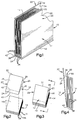
- Fig. 1
- eine fragmentarische schematische Darstellung eines Heftes oder einer Bogenmaterial-Zusammenstellung, bei der das erfindungsgemäße Verfahren angewandt wurde;
- Fig. 2
- eine schematische Darstellung der Weise, wie ein Umschlag mit der Innenseite nach außen relativ zu einem Ende eines Signaturstapels plaziert wird;
- Fig. 3
- eine schematische Darstellung von dem Verhältnis des Umschlags, dessen Innenseite nach außen gekehrt ist, mit dem Stapel von Signaturen;
- Fig. 4
- eine Ansicht entlang der Linie 4-4 der Fig. 3, welche das Verhältnis zwischen dem Umschlag mit seiner Innenseite nach außen gekehrt und dem Stapel von Signaturen weiterhin darstellt;
- Fig. 5
- eine schematische Darstellung der Weise, wie der mit seiner Innenseite nach
außen gekehrte Umschlag aufgeklappt und dann über den Signaturstapel
gefalzt wird, während sich der Signaturstapel parallel zu den gefalzten Kanten
der
Signaturen bewegt; - Fig. 6
- eine Schnittansicht eines Teils einer bekannten Vorrichtung, die zur Bildung des Stapels von Signaturen mit dem in den Fig. 3 und 4 gezeigten Umschlag, dessen Innenseite nach außen gekehrt ist, verwendet werden kann;
- Fig. 7
- eine schematische Darstellung einer alternativen bekannten Vorrichtung, die zur Bildung des Stapels von Signaturen mit dem in den Fig. 3 und 4 gezeigten Umschlag, dessen Innenseite nach außen gekehrt ist, verwendet werden kann;
- 10
- Bogenmaterial-Zusammenstellung
- 12
- Umschlag
- 14
- Stapel
- 16
- Signaturen
- 16a
- vordere (erste) Signatur des Stapels 14
- 16b
- hintere (letzte) Signatur des Stapels 14
- 20
- vorderes (erstes) Umschlagteil des Umschlags 12
- 22
- hinteres (zweites) Umschlagteil des Umschlags 12
- 24
- Rücken des Umschlags 12
- 28
- Außenfläche des Umschlagteils 20
- 30
- Innenfläche des Umschlagteils 20
- 32
- Außenfläche des Umschlagteils 22
- 34
- Innenfläche des Umschlagteils 22
- 38
- gefalzte Kante der Signatur 16
- 40
- vorderer Falz des Umschlags 12
- 42
- hinterer Falz des Umschlags 12
- 50
- Aufklapp-/Falzeinrichtung
- 52
- Aufklappabschnitt von 50
- 54
- Messer
- 56
- Pfeil
- 58
- Klebstoff-Auftragabschnitt
- 60
- Klebstoff-Augtragrolle
- 72
- Pressrolle
- 80
- Bogenmaterial-Zusammentragmechanismus
- 82
- Zusammentrageinheit
- 84
- Pfeil
- 86
- Magazine
- 90
- Signaturstapel (Fig. 6)
- 94
- Zuführmechanismus (Fig. 6)
- 96
- Aufnahmetasche (Fig. 6)
- 100
- Sauggreifer (Fig. 6)
- 120
- Flachform-Zusammentragmechanismus
- 122
- Magazine
- 124
- Förderband
- 130
- Zuführmechanismus
- 132
- Aufnahmestellen
- 134
- Schiebeelement
- 136
- Transportkette
- 140
- Pfeil
Claims (14)
- Verfahren zur Bildung einer Bogenmaterial-Zusammenstellung mit einem Umschlag, welches die folgenden Schritte umfaßt:das Bilden eines Stapels (14) von Signaturen (16), wobei der Umschlag (12) an einem Ende des Stapels (14) plaziert und die Innenfläche (30) eines ersten Umschlagteils (20) mit einer Signatur (16a) des Signaturstapels (14) in Kontakt ist, die Außenfläche (28) des ersten Umschlagteils (20) und die Außenfläche (32) eines zweiten Umschlagteils (22) einander zugekehrt sind, und die Innenfläche (34) des zweiten Umschlagteils (22) von dem Signaturstapel (14) abgekehrt ist; unddas Bewegen des zweiten Umschlagteiles (22) weg von dem ersten Umschlagteil (20) und in den Kontakt mit einer Signatur (16b) an einem dem einen Ende gegenüberliegenden Ende des Stapels (14), während die Innenfiäche (30) des ersten Umschlagteils (20) in Kontakt mit der Signatur (16a) an dem einen Ende des Signaturstapels (14) bleibt.
- Verfahren nach Anspruch 1, das den folgenden weiteren Schritt umfaßt:das Auftragen von Klebstoff auf den Signaturstapel (14), bevor das zweite Umschlagteil (22) des Umschlags (12) in den Kontakt mit der Signatur (16b) des Stapels (14) gegenüber der einen Signatur (16a) bewegt wird, während die Innenfläche (30) des ersten Umschlagteils (20) des Umschlags (12) in Kontakt mit der einen Signatur (16a) des Stapels (14) bleibt.
- Verfahren nach Anspruch 1,
dadurch gekennzeichnet, daß in dem Schritt der Bildung eines Stapels (14) von Signaturen (16) mit einem Umschlag (12) an einem Ende des Stapels die Signaturen (16) zur Bildung eines Teilstapels quer zu den gefalzten Kanten (38) der Signaturen (16) bewegt und weitere Signaturen (16) zu dem Stapel (14) hinzugefügt werden, und daß im weiteren Verlauf der Stapel (14) von Signaturen (16) und der Umschlag (12) parallel zu den gefalzten Kanten (38) der Signaturen (16) bewegt werden, wobei der Schritt, das zweite Umschlagteil (22) weg vom ersten Umschlagteil (20) zu bewegen, erfolgt, während der Signaturstapel (14) parallel zu den gefalzten Kanten (38) der Signaturen (16) bewegt wird. - Verfahren nach Anspruch 3, das folgenden weiteren Schritt umfaßt:das Auftragen von Klebstoff auf mindestens eine von zwei Auftragsflächen, nämlich den Umschlag (12) oder den Signaturstapel (14), während der Signaturstapel (14) und der Umschlag (12) parallel zu den gefalzten Kanten (38) der Signaturen (16) bewegt werden.
- Verfahren nach Anspruch 1,
dadurch gekennzeichnet,daß der Schritt, das zweite Umschlagteil (22) weg vom ersten Umschlagteil (20) des Umschlags (12) und in den Kontakt mit einer Signatur (16b) eines Endes gegenüber dem einen Ende des Signaturstapels (14)zu bewegen, das Schwenken des zweiten Umschlagteils (22) relativ zum ersten Umschlagteil (20) um eine Verbindung (24) zwischen dem ersten und zweiten Umschlagteil (20, 22) des Umschlags (12) umfaßt. - Verfahren nach Anspruch 1,
dadurch gekennzeichnet,daß der Schritt, das zweite Umschlagteils (22) weg vom ersten Umschlagteil (20) des Umschlags (12) und in den Kontakt mit einer Signatur (16b) eines Endes gegenüber dem einen Ende des Signaturstapels (14) zu bewegen, das Bewegen des zweiten Umschlagteils (22) einschließt, und zwar von einer Position, in der sich das erste und das zweite Umschlagteil 20, 22 an einer Seite des Signaturstapels (14) befinden, in eine Position, in der sich das erste Umschlagteil (20) an einer Seite des Signaturstapels (14) und das zweite Umschlagteil (22) an einer der einen Seite gegenüberliegenden Seite des Signaturstapels (14) befinden, wobei sich ein Abschnitt (24) des Umschlags (12) über die gefalzten Kanten (38) der Signaturen (16) des Signaturstapels (14) erstreckt. - Verfahren nach Anspruch 1,
dadurch gekennzeichnet,daß der Schritt der Bildung eines Stapels (14) von Signaturen (12) mit einem Umschlag (12) an einem Ende des Stapels (14) das Positionieren des Umschlags (12) und des Signaturstapels (14) einschließt, wobei der Umschlag (12) zu einer Seite des Signaturstapels (14) hin versetzt ist und die gefalzten Kanten (38) der Signaturen (16) offenliegen , und daß der Schritt des Bewegens des zweiten Umschlagteils (22) weg vom ersten Umschlagteil (20) des Umschlags (12) und in den Kontakt mit einer Signatur (16b) an dem dem einen Ende des Stapels (14) gegenüberliegenden Ende das Bewegen eines Abschnitts (24) des Umschlags (12) über die gefalzten Kanten (38) der Signaturen (16) einschließt, um die gefalzten Kanten (38) der Signaturen (16) des Signaturstapels (14) zu umhüllen. - Verfahren zur Bildung einer Bogenmaterial-Zusammenstellung mit einem Umschlag, welches die folgenden Schritte umfaßt:die Bildung einer Zusammenstellung gefalzter Signaturen (16), indem Signaturen (16) quer zu den gefalzten Kanten (38) der Signaturen (16) bewegt und weitere Signaturen zu den sich bewegenden Signaturen (16) hinzugefügt werden; das Versehen eines Endes des Stapels (90) gefalzter Signaturen (16) mit einem gefalzten Umschlag (12), dessen Innenseite nach außen gekehrt ist und der zwei Umschlagteile (20, 22) aufweist;das anschließende Bewegen des Stapels (90) gefalzter Signaturen (16) und des Umschlags (12) parallel zu den gefalzten Kanten (38) der Signaturen (16), während der Umschlag (12) mit seiner Innenseite nach außen gekehrt ist; unddas Bewegen eines der Umschlagteile (20, 22) über die gefalzten Kanten (38) der Signaturen (16) zu einem dem einen Ende gegenüberliegenden Ende des Signaturstapels (90), während der Signaturstapel (90) und der Umschlag (12) parallel zu den gefalzten Kanten (38) der Signaturen (16) bewegt wird.
- Verfahren nach Anspruch 8, das den folgenden weiteren Schritt umfaßt:das Auftragen von Klebstoff auf mindestens eine von zwei Auftragsflächen, nämlich den Umschlag (12) oder die gefalzten Kanten (38) der Signaturen(16), während der Stapel (90) von Signaturen (16) und der Umschlag (12) parallel zu den gefalzten Kanten (38) der Signaturen (16) bewegt werden.
- Verfahren nach Anspruch 8,
dadurch gekennzeichnet,daß der Schritt der Bewegung des Stapels (90) gefalzter Signaturen (16) und des Umschlags (12) parallel zu den gefalzten Kanten der Signaturen (16) und des Umschlags (12) mit seiner Innenseite nach außen gekehrt durchgeführt wird, indem die Innenfläche (30) des ersten Umschlagteils (20) des Umschlags (12) in Kontakt mit einer Signatur an einem Ende des Signaturstapels (90) ist, die Außenflächen (28, 32) der beiden Umschlagteile (20, 22) in Kontakt mit dem Signaturstapel (90) sind, und die Innenfläche 34) des zweiten Umschlagteiles (22) vom Signaturstapel (90) abgekehrt ist. - Verfahren nach Anspruch 8,
dadurch gekennzeichnet,daß der Schritt der Bewegung der Umschlagteile (20, 22) über die gefalzten Kanten (38) der Signaturen (16) das Bewegen der Innenfläche (34) des zweiten Umschlagteils (22) in den Kontakt mit einer Signatur an einem dem einen Ende gegenüberliegenden Ende des Signaturstapels (90) einschließt. - Verfahren nach Anspruch 8,
dadurch gekennzeichnet,daß der Schritt, eines der Teile (20, 22) des Umschlags (12) über die gefalzten Kanten (38) der Signaturen zu bewegen, das Schwenken des einen Umschlagteils um eine Verbindung (24) zwischen den Umschlagteilen (20, 22) des Umschlags (12) einschließt. - Verfahren nach Anspruch 8,
dadurch gekennzeichnet,daß der Schritt, eines der Teile (20, 22) des Umschlags (12) über die gefalzten Kanten (38) der Signaturen zu bewegen, das Bewegen eines Abschnitts (24) des Umschlags (12) in den Kontakt mit den gefalzten Kanten (38) der Signaturen (16) einschließt. - Verfahren nach Anspruch 8,
dadurch gekennzeichnet,daß der Schritt, eines der Teile (20, 22) des Umschlags (12) über die gefalzten Kanten (38) der Signaturen zu bewegen, das Aufklappen des Umschlags (12) und das erneute Falzen des Umschlags (12) einschließt.
Applications Claiming Priority (2)
| Application Number | Priority Date | Filing Date | Title |
|---|---|---|---|
| US08/927,954 US5975823A (en) | 1997-09-11 | 1997-09-11 | Method of forming sheet material assemblage |
| US927954 | 1997-09-11 |
Publications (3)
| Publication Number | Publication Date |
|---|---|
| EP0901908A2 true EP0901908A2 (de) | 1999-03-17 |
| EP0901908A3 EP0901908A3 (de) | 1999-05-06 |
| EP0901908B1 EP0901908B1 (de) | 2002-07-03 |
Family
ID=25455496
Family Applications (1)
| Application Number | Title | Priority Date | Filing Date |
|---|---|---|---|
| EP98115156A Expired - Lifetime EP0901908B1 (de) | 1997-09-11 | 1998-08-12 | Verfahren zum Bilden einer Bogenmaterial-Zusammenstellung |
Country Status (4)
| Country | Link |
|---|---|
| US (1) | US5975823A (de) |
| EP (1) | EP0901908B1 (de) |
| JP (1) | JPH11151873A (de) |
| DE (1) | DE59804638D1 (de) |
Families Citing this family (4)
| Publication number | Priority date | Publication date | Assignee | Title |
|---|---|---|---|---|
| DE59813367D1 (de) * | 1998-11-02 | 2006-04-13 | Grapha Holding Ag | Verfahren zur Herstellung von Druckerzeugnissen |
| US6494661B1 (en) * | 2000-05-12 | 2002-12-17 | Heidelberger Druckmaschinen Ag | Device and method for providing a cover for a book |
| US6866459B2 (en) * | 2001-02-26 | 2005-03-15 | Hewlett-Packard Development Company, L.P. | Systems and methods of registering a cover with respect to a text body |
| US6948897B2 (en) * | 2001-11-08 | 2005-09-27 | Hewlett-Packard Development Company, L.P. | Systems and methods for assembling and binding publications |
Family Cites Families (14)
| Publication number | Priority date | Publication date | Assignee | Title |
|---|---|---|---|---|
| US2895730A (en) * | 1954-04-30 | 1959-07-21 | Hans Sickinger | Apparatus for making articles stitched along a fold |
| US4170346A (en) * | 1977-11-03 | 1979-10-09 | Harris Corporation | Bindery caliper |
| CA1205702A (en) * | 1981-11-24 | 1986-06-10 | Ferag Ag | Method and apparatus for opening multi-sheet products, especially printed products |
| US4420148A (en) * | 1982-03-22 | 1983-12-13 | The Wessel Company, Inc. | Method and apparatus for folding a cover strip over a multi-ply inner strip |
| US4477067A (en) * | 1982-05-10 | 1984-10-16 | Harris Graphics Corporation | Method and apparatus for assembling sheet material assemblages |
| US4641825A (en) * | 1985-05-22 | 1987-02-10 | Harris Graphics Corporation | Collator with moveable stitcher over saddle conveyor system |
| US4988086A (en) * | 1989-01-26 | 1991-01-29 | Am International Incorporated | Apparatus and method for forming sheet material assemblages |
| US5067699A (en) * | 1990-02-07 | 1991-11-26 | Am International Incorporated | Sheet material handling apparatus with inserter assembly |
| US5232324A (en) * | 1991-10-07 | 1993-08-03 | Quad/Tech, Inc. | Apparatus and method for applying covers to signatures |
| US5261769A (en) * | 1992-08-04 | 1993-11-16 | Am International Incorporated | Book binding apparatus and method |
| DE4334225B4 (de) * | 1993-10-07 | 2005-04-28 | Kolbus Gmbh & Co Kg | Buchfertigungsstraße |
| US5622268A (en) * | 1994-11-30 | 1997-04-22 | Heidelberg Finishing Systems, Inc. | Apparatus for calipering a collated assemblage |
| US5615871A (en) * | 1996-01-26 | 1997-04-01 | Heidelberg Finishing Systems, Inc. | Sheet material handling apparatus and method |
| JP3165957B2 (ja) * | 1996-03-13 | 2001-05-14 | ホリゾン・インターナショナル株式会社 | 中綴折機 |
-
1997
- 1997-09-11 US US08/927,954 patent/US5975823A/en not_active Expired - Fee Related
-
1998
- 1998-08-12 EP EP98115156A patent/EP0901908B1/de not_active Expired - Lifetime
- 1998-08-12 DE DE59804638T patent/DE59804638D1/de not_active Expired - Lifetime
- 1998-09-11 JP JP10258423A patent/JPH11151873A/ja not_active Ceased
Also Published As
| Publication number | Publication date |
|---|---|
| JPH11151873A (ja) | 1999-06-08 |
| EP0901908B1 (de) | 2002-07-03 |
| DE59804638D1 (de) | 2002-08-08 |
| EP0901908A3 (de) | 1999-05-06 |
| US5975823A (en) | 1999-11-02 |
Similar Documents
| Publication | Publication Date | Title |
|---|---|---|
| DE3047436C2 (de) | ||
| DE69106464T2 (de) | Einrichtung zum öffnen von gefalteten Druckereierzeugnissen. | |
| EP0606550B1 (de) | Vorrichtung zum Zubringen von flächigen Erzeugnissen zu einer Verarbeitungseinrichtung für Druckereiprodukte | |
| EP0354343B1 (de) | Verfahren zum Herstellen von mehrteiligen Druckereierzeugnissen, nach diesem Verfahren hergestelltes Druckereierzeugnis und Vorrichtung zur Durchführung des Verfahrens | |
| DE2209566A1 (de) | Verfahren und Vorrichtung zur Her stellung aus einer Vielzahl von Papierbogen zusammengefugter Bucher, Broschüren oder Hefte | |
| DE19750110A1 (de) | Sammelhefter | |
| EP2955138B1 (de) | Verfahren zum herstellen von kollektionen aus einer vielzahl von unterschiedlichen werbeprospekten sowie vorrichtung zur durchführung des verfahrens | |
| DE69107607T2 (de) | Vorrichtung zum Öffnen. | |
| EP1939008A2 (de) | Sammelhefter mit variabler Kettenteilung | |
| EP0681979B1 (de) | Einrichtung zum Verarbeiten von Druckereiprodukten | |
| EP0901908B1 (de) | Verfahren zum Bilden einer Bogenmaterial-Zusammenstellung | |
| EP0250758A1 (de) | Falz- und Transportvorrichtung | |
| DE102013017223A1 (de) | Vorrichtung zur Bildung von Buchblöcken | |
| CH689691A5 (de) | Verfahren für das Anbringen eines Umschlages am Rücken eines aus gebundenen Druckbogen gebildeten Buchblockes und Vorrichtung zur Durchführung desselben. | |
| DE69800649T2 (de) | Buchbindemaschine | |
| DE102008004434A1 (de) | Verfahren zum Betreiben einer Buchbindemaschine | |
| DE4207069A1 (de) | Vorrichtung zum leiten von blaettern auf eine ablageflaeche | |
| DE2829177C2 (de) | Verfahren und Vorrichtung zur maschinellen Herstellung von mit bedruckten Kalenderlaschen versehenen Kalendern | |
| EP0178408B1 (de) | Vorrichtung zum Übereinanderlegen von biegsamen Flächengebilden, insbesondere von Blättern und Bogen | |
| DE10121246A1 (de) | Vorrichtung und Verfahren zum seitlichen Binden von Druckprodukten | |
| EP2844593B1 (de) | Verfahren und vorrichtung zum öffnen von druckereiprodukten | |
| DE3444576A1 (de) | Verfahren und vorrichtung zur herstellung von buechern, insbesondere taschenbuechern, broschueren und zeitschriften | |
| DE3100866A1 (de) | Maschine zum transportieren einer folge von buechern | |
| DE19725605A1 (de) | Verfahren und Vorrichtung zur Herstellung von mit Beilagen versehenen Falzexemplaren | |
| CH690614A5 (de) | Verfahren zum Auflegen von Druckbogen auf einen Heftsattel einer Buchfadenheftmaschine und Vorrichtung zur Durchführung des Verfahrens. |
Legal Events
| Date | Code | Title | Description |
|---|---|---|---|
| PUAI | Public reference made under article 153(3) epc to a published international application that has entered the european phase |
Free format text: ORIGINAL CODE: 0009012 |
|
| 17P | Request for examination filed |
Effective date: 19980812 |
|
| AK | Designated contracting states |
Kind code of ref document: A2 Designated state(s): BE CH DE FR GB IT LI NL |
|
| AX | Request for extension of the european patent |
Free format text: AL;LT;LV;MK;RO;SI |
|
| PUAL | Search report despatched |
Free format text: ORIGINAL CODE: 0009013 |
|
| AK | Designated contracting states |
Kind code of ref document: A3 Designated state(s): AT BE CH CY DE DK ES FI FR GB GR IE IT LI LU MC NL PT SE |
|
| AX | Request for extension of the european patent |
Free format text: AL;LT;LV;MK;RO;SI |
|
| AKX | Designation fees paid |
Free format text: BE CH DE FR GB IT LI NL |
|
| GRAG | Despatch of communication of intention to grant |
Free format text: ORIGINAL CODE: EPIDOS AGRA |
|
| GRAG | Despatch of communication of intention to grant |
Free format text: ORIGINAL CODE: EPIDOS AGRA |
|
| GRAH | Despatch of communication of intention to grant a patent |
Free format text: ORIGINAL CODE: EPIDOS IGRA |
|
| 17Q | First examination report despatched |
Effective date: 20011210 |
|
| GRAH | Despatch of communication of intention to grant a patent |
Free format text: ORIGINAL CODE: EPIDOS IGRA |
|
| GRAA | (expected) grant |
Free format text: ORIGINAL CODE: 0009210 |
|
| AK | Designated contracting states |
Kind code of ref document: B1 Designated state(s): BE CH DE FR GB IT LI NL |
|
| PG25 | Lapsed in a contracting state [announced via postgrant information from national office to epo] |
Ref country code: NL Free format text: LAPSE BECAUSE OF FAILURE TO SUBMIT A TRANSLATION OF THE DESCRIPTION OR TO PAY THE FEE WITHIN THE PRESCRIBED TIME-LIMIT Effective date: 20020703 Ref country code: IT Free format text: LAPSE BECAUSE OF FAILURE TO SUBMIT A TRANSLATION OF THE DESCRIPTION OR TO PAY THE FEE WITHIN THE PRE;WARNING: LAPSES OF ITALIAN PATENTS WITH EFFECTIVE DATE BEFORE 2007 MAY HAVE OCCURRED AT ANY TIME BEFORE 2007. THE CORRECT EFFECTIVE DATE MAY BE DIFFERENT FROM THE ONE RECORDED.SCRIBED TIME-LIMIT Effective date: 20020703 Ref country code: GB Free format text: LAPSE BECAUSE OF FAILURE TO SUBMIT A TRANSLATION OF THE DESCRIPTION OR TO PAY THE FEE WITHIN THE PRESCRIBED TIME-LIMIT Effective date: 20020703 Ref country code: FR Free format text: LAPSE BECAUSE OF FAILURE TO SUBMIT A TRANSLATION OF THE DESCRIPTION OR TO PAY THE FEE WITHIN THE PRESCRIBED TIME-LIMIT Effective date: 20020703 |
|
| REG | Reference to a national code |
Ref country code: CH Ref legal event code: EP |
|
| REF | Corresponds to: |
Ref document number: 59804638 Country of ref document: DE Date of ref document: 20020808 |
|
| PG25 | Lapsed in a contracting state [announced via postgrant information from national office to epo] |
Ref country code: BE Free format text: LAPSE BECAUSE OF NON-PAYMENT OF DUE FEES Effective date: 20020831 |
|
| NLV1 | Nl: lapsed or annulled due to failure to fulfill the requirements of art. 29p and 29m of the patents act | ||
| GBV | Gb: ep patent (uk) treated as always having been void in accordance with gb section 77(7)/1977 [no translation filed] |
Effective date: 20020703 |
|
| EN | Fr: translation not filed | ||
| BERE | Be: lapsed |
Owner name: *HEIDELBERGER DRUCKMASCHINEN A.G. Effective date: 20020831 |
|
| PLBE | No opposition filed within time limit |
Free format text: ORIGINAL CODE: 0009261 |
|
| STAA | Information on the status of an ep patent application or granted ep patent |
Free format text: STATUS: NO OPPOSITION FILED WITHIN TIME LIMIT |
|
| 26N | No opposition filed |
Effective date: 20030404 |
|
| PGFP | Annual fee paid to national office [announced via postgrant information from national office to epo] |
Ref country code: CH Payment date: 20100825 Year of fee payment: 13 |
|
| PGFP | Annual fee paid to national office [announced via postgrant information from national office to epo] |
Ref country code: DE Payment date: 20100827 Year of fee payment: 13 |
|
| REG | Reference to a national code |
Ref country code: CH Ref legal event code: PL |
|
| PG25 | Lapsed in a contracting state [announced via postgrant information from national office to epo] |
Ref country code: CH Free format text: LAPSE BECAUSE OF NON-PAYMENT OF DUE FEES Effective date: 20110831 Ref country code: LI Free format text: LAPSE BECAUSE OF NON-PAYMENT OF DUE FEES Effective date: 20110831 |
|
| REG | Reference to a national code |
Ref country code: DE Ref legal event code: R119 Ref document number: 59804638 Country of ref document: DE Effective date: 20120301 |
|
| PG25 | Lapsed in a contracting state [announced via postgrant information from national office to epo] |
Ref country code: DE Free format text: LAPSE BECAUSE OF NON-PAYMENT OF DUE FEES Effective date: 20120301 |