EP0901908B1 - Méthode pour former une composition de matérial en feuilles - Google Patents
Méthode pour former une composition de matérial en feuilles Download PDFInfo
- Publication number
- EP0901908B1 EP0901908B1 EP98115156A EP98115156A EP0901908B1 EP 0901908 B1 EP0901908 B1 EP 0901908B1 EP 98115156 A EP98115156 A EP 98115156A EP 98115156 A EP98115156 A EP 98115156A EP 0901908 B1 EP0901908 B1 EP 0901908B1
- Authority
- EP
- European Patent Office
- Prior art keywords
- signatures
- cover
- stack
- envelope
- folded edges
- Prior art date
- Legal status (The legal status is an assumption and is not a legal conclusion. Google has not performed a legal analysis and makes no representation as to the accuracy of the status listed.)
- Expired - Lifetime
Links
- 238000000034 method Methods 0.000 title claims description 26
- 239000000463 material Substances 0.000 title claims description 19
- 239000000853 adhesive Substances 0.000 claims description 13
- 230000001070 adhesive effect Effects 0.000 claims description 13
- 230000007246 mechanism Effects 0.000 description 18
- 239000003292 glue Substances 0.000 description 6
- 229920001817 Agar Polymers 0.000 description 1
- 230000001154 acute effect Effects 0.000 description 1
- 230000015572 biosynthetic process Effects 0.000 description 1
- 238000010276 construction Methods 0.000 description 1
Images

Classifications
-
- B—PERFORMING OPERATIONS; TRANSPORTING
- B42—BOOKBINDING; ALBUMS; FILES; SPECIAL PRINTED MATTER
- B42C—BOOKBINDING
- B42C19/00—Multi-step processes for making books
- B42C19/04—Multi-step processes for making books starting with signatures
Definitions
- the present invention relates to a method for forming a sheet material assembly, such as B. a booklet or magazine with an envelope, that envelops a variety of signatures.
- the signatures be offset with their folded edges.
- the arrangement of the folded edges of the signatures with respect to the side surfaces of the signatures beveled at an acute angle.
- the adhesive is applied to the folded edges of the signatures and then the Envelope pressed against it.
- this process Difficulties may arise.
- the present invention provides an improved method for forming a booklet, a magazine or other sheet material compilation.
- an envelope is folded inside out and at one end a stack of signatures.
- the inner surface of a first or front part of the envelope placed inside out contacts a signature of the Signature stack.
- the outer surfaces of the cover parts face each other.
- the Inner surface of the second or back part of the envelope is from the signature stack averted.
- the second part of the envelope is then the first part of the Envelope away and moved into contact with the signature stack.
- the second Cover part contacts one end of the signature stack opposite the end of that first envelope part is contacted.
- the stack of folded signatures is formed by placing the signatures across the folded one Edge of the signatures moved and further signatures to the moving signatures to be added.
- the folded envelope is at one end of the stack inside out.
- the stack of folded signatures and the Envelope with its inside turned outwards are then parallel to the Folded edges of the signatures moved.
- One of the envelope parts is placed over the Folded edges of the signatures at one end of the signature stack opposite that of the other envelope part contacted end moved.
- a glue-bound booklet, magazine, or similar sheet material compilation 10 (Fig. 1) includes an envelope 12 which is a stack or a Group 14 enveloped by folded signatures 16.
- the envelope has a front or first cover part 20 and a rear or second cover part 22, which by a spine or connecting portion 24 of the envelope 12 joined together are.
- the front envelope member 20 has an uncovered outer surface 28 and one Inner surface 30 on. The inner surface 30 of the front envelope part 20 of the envelope 12 is against a front end of the stack or group 14 of signatures 16 pressed.
- the rear envelope 22 has an uncovered outer surface 32 and an inner surface 34.
- the inner surface 34 of the rear cover part 22 is against a rear end of the stack or group 14 of signatures 16 is pressed.
- the Signatures 16 have folded edge parts 38 which are glued together connected and in contact with the back 24 of the envelope 12.
- a front and a rear fold 40 and 42 connect the back 24 and the front and rear Cover part 20 and 22 of the envelope 12 with each other.
- the illustrated booklet 10 has a flat spine 24, the front and rear part 20 and 22 of the envelope 12 connects, it is conceivable that the Back 24 a substantially U-shaped or even V-shaped as desired Can have structure.
- the envelope 12 shown consists of sheet material that is heavier than the sheet material of the signatures 16. However, it is also conceivable that the signatures 16 are made with material that is the same specific Weight as the material of the envelope 12 has.
- the signature stack 14 corresponds to that in FIG. 2 shown schematic representation collated.
- the folded edges 38 of the Signatures 16 are aligned with one another.
- the front or first signature 16a and the rear or second signature 16b in the signature stack 14 are only exposed.
- the Envelope 12 is moved towards the signature stack 14, as shown schematically in FIG. 2 is indicated.
- the envelope 12 is along the front fold line 40 from the inside folded outwards.
- the outer surface 28 of the front envelope 20 is the Outer surface 32 of the rear cover part 22 faces and is in with the latter Contact.
- the inner surfaces 30 and 34 of the front and rear envelope parts are uncovered and turned away from each other. Since the envelope 12 along the front Fold line 40 is folded, the upper edge of the rear cover part 22 extends of the envelope 12 beyond the edge of the front envelope portion 20 (as in FIG. 2 shown). At this point, envelope 12 is not yet along the rear Fold line 42 folded and the back 24 of the envelope 12 combines with the width of the rear cover part 22 and exceeds the width of the front cover part 20.
- the envelope 12 with the inside out is moved down (as in FIG. 2 shown) and further along a path perpendicular to the front fold line 40 runs so that the envelope 12 in the same direction as the signature stack 14 is positioned (see Figs. 3 and 4).
- the folded edges 38 of the signatures 16 are as shown beveled or slightly offset relative to each other to apply to facilitate the glue on the signatures. If desired, however, the adhesive can applied to the folded edges 38 of the signatures aligned with each other become.
- the envelope 12 is turned inside out in Figs. 2-4 as on the the first signature 16a of the signature stack 14 is shown placed.
- the envelope 12 can however, also be placed on the last signature 16b of the signature stack 14. In the latter
- the case 12 is folded along the rear fold line 42, and the Inner surface 34 of the rear envelope 22 is in contact with the last signature 16b the signature stack 14.
- a pop-up / folder 50 (Fig. 5) is used to first pull the one with the Unfold envelope 12 folded outwards and then envelope 12 to fold with the right side outwards over the stack 14 of the signatures 16 again.
- the folding / folding device 50 comprises a folding section 52 with a Knife 54, which is between the front and rear cover parts 20 and 22nd inside moves.
- the knife 54 opens the envelope 12 while the Signature stack 14 and envelope 12 in the direction of the arrow shown in FIG. 5 move.
- the signature stack 14 and the envelope 12 turned inside out are along the flip section 52 and parallel to the folded edges 38 of the Signatures 16 and the front fold line 40 of the envelope 12 moves. It pivots the knife 54, the rear envelope 22 by 180 ° around the front fold line 40, so that the envelope 12 from the inside folded state to the unfolded or flat state is moved, as shown in Fig. 5.
- a pressure roller 72 exerts pressure on the edge of booklet 10. This force provides the connection between envelope 12 and Signatures 16 ago and through the adhesive, the signatures 16 are with each other and with connected to the envelope 12.
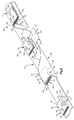
- the stack 14 of signatures and the envelope 12 can be used in a variety of ways different collation mechanisms. It is assumed, that a known collation mechanism 80 such as that shown in FIG. 6 is preferred comprising a plurality of sheet material gathering units 82.
- the Sheet material gathering units 82 are connected to one another and are inserted into the moved by an arrow 84 in Fig. 6 direction, along a continuous path below stationary, bottomless magazines 86 Signatures are fed from the stacks with the folded edges 38 ahead while the collating units 82 are sequentially among each of the stationary ones Move stack 90 of signatures 16.
- Each collator 82 includes a feed mechanism 94 and one Recording pocket 96 on.
- the feed mechanism 94 is vacuum or Suction pads 100 equipped that have a lowermost signature 16 in the signature stack 90 take.
- the suction pads 100 move a captured signature down and along a path between bands 102 to the receiving pocket 96.
- By means of the Feed mechanism 94 can sequentially feed the sheet material from each of stacks 90 a single pocket 96 can be fed.
- the collating unit 82 does not move in the direction 84 along one shown magazine, which contains envelopes 12, the inside of which is turned outwards.
- Such an envelope 12 folded with its inside out is then by the Feed mechanism 94 down from the magazine into the receiving pocket 96 fed, with his front fold 40 ahead.
- the collating unit 82 becomes perpendicular to the folded edges 38 of the signatures 16 are moved to a delivery station. There the Bottom of the receiving pocket 96 opened and the stack 14 of signatures 16 and Envelope 12 with its inside out are on a conveyor belt (not shown) placed. The conveyor belt moves the signature stack 14 and the opened one Envelope 12 for the folding and folding device 50, the signature stack 14 and the opened envelope 12 have the orientation shown in Fig. 5.
- collating mechanism 80 The construction and operation of the collating mechanism 80 is the same such as the collation mechanism disclosed in US 4,988,086. Although assumed will be that the device disclosed in that U.S. patent is the first one Signature stack 14 is formed and then envelope 12 is added to the stack, is preferred, the device could also be constructed and actuated in this way as disclosed in US 4,721,296.
- the above description of the operation of the collating mechanism 80 lies on the basis that the signature stack 14 is formed first and the envelope 12 with his Inside out is added to the stack.
- the envelope 12 could however, can also be fed into the receiving pocket 96 before the signatures 16. Accordingly, the signature stack 14 would be formed next to the envelope 12 during the Cover 12 is moved along the respective magazine 86.
- the signature stack 14 and the envelope 12 are so on the delivery conveyor belt oriented that both move parallel to the folded edges 38 of the signatures 16, the envelope 12 is located under the signature stack 14.
- the signature stack 14 and the envelope 12 then get into the opening section 52 of the opening and closing Folding device 50 (see Fig. 5).
- the flip open and Folding device 50 with its inside out envelope 12 and folds it back around the signature stack 14.
- collating mechanism 80 with the receiving pockets 96 with it opening bottom for receiving the signatures 16 and the envelope 12 the preference other types of collation mechanisms can be provided be used .
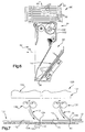
- a known flat form collating mechanism 120 for Formation of the signature stack 14 with the associated, with their inside to the outside reversed envelopes 12 is shown schematically in Fig. 7.
- the collating mechanism 120 comprises a series of stationary magazines 122.
- a straight conveyor belt 124 extends below the row of magazines 122. Although only two magazines 122 are shown in FIG. 7, it goes without saying that in the linear series of magazines of each signature 16 in the signature stack 14 and a magazine is associated with the respective envelope 12.
- known feed mechanisms 130 are associated with each of the Magazine 122 shown schematically.
- the feed mechanism 130 conveys the Envelopes 12 turned inside out and the folded signatures 16 closed Receiving points 132, which are connected between a transport chain 136 Sliding elements 134 are located.
- each magazine 122 becomes a different one Folded signature 16 with their folded edge 38 fed in order. If a signature stack 14 has formed at the receiving point 132 (FIG. 2), this becomes placed on an envelope 12, the inside of which is turned outwards.
- the signature stack moves perpendicular to the folded edges 38 of the signatures, as shown schematically by arrow 140 in FIG. 7 is indicated.
- the complete signature stack 14 then reaches one Delivery conveyor that changes the orientation of the stack so that the envelope 12th and the signature stack 14 parallel to the folded edge 38 of the signatures 16 and Cover fold line 42 are moved. Then the signature stack 14 and the Envelope in the folding / folding device 50 (Fig. 5) moves.
- the present one Invention for a new and improved method for forming a booklet, one Magazine or other sheet material compilation 10.
- an envelope 12 is folded inside out and on one End of a stack 14 of signatures 16 placed.
- the inner surface 30 of a first Cover part 20 is in contact with one of the signatures 16 of the signature stack 14.
- the Outer surfaces 28 and 32 of the envelope parts 20 and 22 of the envelope 12 are mutually faces.
- the inside 34 of the second envelope part 22 of the envelope 12 is from turned away from the signature stack 14.
- the second envelope part 22 is then the first Envelope part 20 away and in contact with one end of the signature stack 14 moves while the first envelope 20 with the opposite other end signature stack 14 is in contact.
- the stack 14 of folded signatures 16 is formed by the signatures 16 across moved to the folded edges 38 of the signatures 16 and further signatures to these moving signatures.
- the folded envelope 12 with his Inverted outward is positioned at one end of signature stack 14.
- the Stack 14 of folded signatures 16 and the inside out Envelope 12 is then moved parallel to the folded edges 38 of the signatures 16.
- the rear cover part 22 of the cover 12 is folded over the folded edges 38 of the signatures 16 moves to one end of the signature stack 14 which is that of the front envelope part 20 of the envelope 12 opposite end opposite.
Landscapes
- Collation Of Sheets And Webs (AREA)
- Helmets And Other Head Coverings (AREA)
- Folding Of Thin Sheet-Like Materials, Special Discharging Devices, And Others (AREA)
- Pile Receivers (AREA)
Claims (14)
- Procédé de formation d'une composition de documents en feuilles, avec une couverture, lequel procédé comprend les étapes suivantes consistant :à former uns pile (14) de cahiers (16), où la couverture (12) est placée à une extrémité de la pile (14) et où la surface intérieure (30) d'une première partie de couverture (20) est en contact avec un cahier (16a) de la pile de cahiers (14), la surface extérieure (28) de la première partie de couverture (20) et la surface extérieure (32) d'une seconde partie de couverture (22) étant tournées l'une vers l'autre, et la surface intérieure (34) de la seconde partie de couverture (22) est à l'opposé de la pile de cahiers (14) ; età éloigner la seconde partie de couverture (22), de la première partie de couverture (20), et en contact avec un cahier (16b) au niveau d'une extrémité de la pile (14) opposée à l'autre extrémité, tandis que la surface intérieure (30) de la première partie de couverture (20) reste en contact avec le cahier (16a) au niveau de l'une des extrémités de la pile de cahiers (14).
- Procédé selon la revendication 1, qui comprend l'autre étape suivante consistant :à appliquer de la colle sur la pile de cahiers (14) avant que la seconde partie de couverture (22) de la couverture (12) soit déplacée en contact avec le cahier (16b) de la pile (14), par rapport à l'un des cahiers (16a), tandis que la surface intérieure (30) de la première partie de couverture (20) de la couverture (12) reste en contact avec l'un des cahiers (16a) de la pile (14).
- Procédé selon la revendication 1, caractérisé en ce que, au cours de l'étape de la formation d'une pile (14) de cahiers (16), avec une couverture (12) au niveau d'une extrémité de la pile, les cahiers (16) sont déplacés transversalement par rapport aux bords pliés (38) des cahiers (16) pour la formation d'une pile partielle, d'autres cahiers (16) étant ajoutés à la pile (14), et en ce que, au cours de la suite du processus, la pile (14) de cahiers (16) et la couverture (12) sont déplacées parallèlement aux bords pliés (38) des cahiers (16), où l'étape consistant à éloigner la seconde partie de couverture (22), de la première partie de couverture (20), se produit alors que la pile de cahiers (14) est déplacée parallèlement aux bords pliés (38) des cahiers (16).
- Procédé selon la revendication 3, qui comprend l'autre étape suivante consistant :à appliquer de la colle sur au moins une des deux surfaces d'application, à savoir sur la couverture (12) ou sur la pile de cahiers (14), tandis que la pile de cahiers (14) et la couverture (12) sont déplacées parallèlement aux bords pliés (38) des cahiers (16).
- Procédé selon la revendication 1, caractérisé en ce que l'étape consistant à éloigner la seconde partie de couverture (22), de la première partie de couverture (20) de la couverture (12), et en contact avec un cahier (16b) d'une extrémité par rapport à l'autre extrémité de la pile de cahiers (14), englobe le mouvement pivotant de la seconde partie de couverture (22) par rapport à la première partie de couverture (20) autour d'une jonction (24) entre les première et seconde parties de couverture (20, 22) de la couverture (12).
- Procédé selon la revendication 1, caractérisé en ce que l'étape consistant à éloigner la seconde partie de couverture (22), de la première partie de couverture (20) de la couverture (12), et en contact avec un cahier (16b) d'une extrémité par rapport à l'autre extrémité de la pile de cahiers (14), englobe le déplacement de la seconde partie de couverture (22), et ce, d'une position dans laquelle les première et seconde parties de couverture (20, 22) se trouvent sur un côté de la pile de cahiers (14), à une position dans laquelle la première partie de couverture (20) se trouve sur un côté de la pile de cahiers (14) et où la seconde partie de couverture (22) se trouve sur un côté de la pile de cahiers (14) opposé à l'autre côté, où une partie (24) de la couverture (12) s'étend au-dessus des bords pliés (38) des cahiers (16) de la pile de cahiers (14).
- Procédé selon la revendication 1, caractérisé en ce que l'étape de la formation d'une pile (14) de cahiers (16), avec une couverture (12) au niveau d'une extrémité de la pile (14), englobe le positionnement de la couverture (12) et de la pile de cahiers (14) où la couverture (12) est déplacée vers un côté de la pile de cahiers (14) et où les bords pliés (38) des cahiers (16) sont dénudés, et en ce que l'étape de l'éloignement de la seconde partie de couverture (22), de la première partie de couverture (20) de la couverture (12), et en contact avec un cahier (16b) au niveau d'une extrémité opposée à l'autre extrémité de la pile (14), englobe le déplacement d'une partie (24) de la couverture (12) au-dessus des bords pliés (38) des cahiers (16), pour envelopper les bords pliés (38) des cahiers (16) de la pile de cahiers (14).
- Procédé de formation d'une composition de documents en feuilles, avec une couverture, lequel procédé comprend les étapes suivantes consistant :à former une composition de cahiers pliés (16), tandis que les cahiers (16) sont déplacés transversalement par rapport aux bords pliés (38) des cahiers (16) et que d'autres cahiers sont ajoutés aux cahiers (16) se déplaçant ;à doter une extrémité de la pile (90) de cahiers pllés (16), d'une couverture pliée (12) dont le côté intérieur est tourné vers l'extérieur et qui comprend deux parties de couverture (20, 22) ;à effectuer le déplacement, qui s'ensuit, de la pile (90) de cahiers pliés (16) et de la couverture (12) parallèlement aux bords pliés (38) des cahiers (16), tandis que la couverture (12), avec son côté intérieur, est tournée vers l'extérieur ; età déplacer une des parties de couverture (20, 22) au-dessus des bords pliés (38) des cahiers (16) jusqu'à une extrémité de la pile de cahiers (90) opposée à l'autre extrémité, tandis que la pile de cahiers (90) et la couverture (12) sont déplacées parallèlement aux bords pliés (38) des cahiers (16).
- Procédé selon la revendication 8, qui comprend l'autre étape suivante consistant :à appliquer de la colle sur au moins une des deux surfaces d'application, à savoir sur la couverture (12) ou sur les bords pliés (38) des cahiers (16), tandis que la pile (90) de cahiers (16) et la couverture (12) sont déplacées parallèlement aux bords pliés (38) des cahiers (16).
- Procédé selon la revendication 8, caractérisé en ce que l'étape du déplacement de la pile (90) de cahiers pliés (16) et de la couverture (12) est effectuée parallèlement aux bords pliés des cahiers (16) et de la couverture (12), le côté intérieur de la couverture étant tourné vers l'extérieur, tandis que la surface intérieure (30) de la première partie de couverture (20) de la couverture (12) est en contact avec un cahier au niveau d'une extrémité de la pile de cahiers (90), que les surfaces extérieures (28, 32) des deux parties de couverture (20, 22) sont en contact avec la pile de cahiers (90) et que la surface intérieure (34) de la seconde partie de couverture (22) est à l'opposé de la pile de cahiers (90).
- Procédé selon la revendication 8, caractérisé en ce que l'étape du déplacement des parties de couverture (20, 22) au-dessus des bords pliés (38) des cahiers (16) englobe le déplacement de la surface intérieure (34) de la seconde partie de couverture (22) en contact avec un cahier au niveau d'une extrémité de la pile de cahiers (90) opposée à l'autre extrémité.
- Procédé selon la revendication 8, caractérisé en ce que l'étape consistant à déplacer une des parties de couverture (20, 22) de la couverture (12) au-dessus des bords pliés (38) des cahiers englobe le mouvement pivotant de l'une des parties de couverture autour d'une jonction (24) entre les parties de couverture (20, 22) de la couverture (12).
- Procédé selon la revendication 8, caractérisé en ce que l'étape consistant à déplacer une des parties de couverture (20, 22) de la couverture (12) au-dessus des bords pliés (38) des cahiers englobe le déplacement d'une partie (24) de la couverture (12) en contact avec les bords pliés (38) des cahiers (16).
- Procédé selon la revendication 8, caractérisé en ce que l'étape consistant à déplacer les parties de couverture (20, 22) de la couverture (12) au-dessus des bords pliés (38) des cahiers englobe l'ouverture de la couverture (12) et le nouveau pliage de la couverture (12).
Applications Claiming Priority (2)
| Application Number | Priority Date | Filing Date | Title |
|---|---|---|---|
| US927954 | 1997-09-11 | ||
| US08/927,954 US5975823A (en) | 1997-09-11 | 1997-09-11 | Method of forming sheet material assemblage |
Publications (3)
| Publication Number | Publication Date |
|---|---|
| EP0901908A2 EP0901908A2 (fr) | 1999-03-17 |
| EP0901908A3 EP0901908A3 (fr) | 1999-05-06 |
| EP0901908B1 true EP0901908B1 (fr) | 2002-07-03 |
Family
ID=25455496
Family Applications (1)
| Application Number | Title | Priority Date | Filing Date |
|---|---|---|---|
| EP98115156A Expired - Lifetime EP0901908B1 (fr) | 1997-09-11 | 1998-08-12 | Méthode pour former une composition de matérial en feuilles |
Country Status (4)
| Country | Link |
|---|---|
| US (1) | US5975823A (fr) |
| EP (1) | EP0901908B1 (fr) |
| JP (1) | JPH11151873A (fr) |
| DE (1) | DE59804638D1 (fr) |
Families Citing this family (4)
| Publication number | Priority date | Publication date | Assignee | Title |
|---|---|---|---|---|
| EP0999074B1 (fr) * | 1998-11-02 | 2006-02-01 | Grapha-Holding Ag | Procédé pour réaliser des produits imprimés |
| US6494661B1 (en) * | 2000-05-12 | 2002-12-17 | Heidelberger Druckmaschinen Ag | Device and method for providing a cover for a book |
| US6866459B2 (en) * | 2001-02-26 | 2005-03-15 | Hewlett-Packard Development Company, L.P. | Systems and methods of registering a cover with respect to a text body |
| US6948897B2 (en) * | 2001-11-08 | 2005-09-27 | Hewlett-Packard Development Company, L.P. | Systems and methods for assembling and binding publications |
Family Cites Families (14)
| Publication number | Priority date | Publication date | Assignee | Title |
|---|---|---|---|---|
| US2895730A (en) * | 1954-04-30 | 1959-07-21 | Hans Sickinger | Apparatus for making articles stitched along a fold |
| US4170346A (en) * | 1977-11-03 | 1979-10-09 | Harris Corporation | Bindery caliper |
| US4486011A (en) * | 1981-11-24 | 1984-12-04 | Ferag Ag | Method and apparatus for opening multi-sheet products, especially printed products |
| US4420148A (en) * | 1982-03-22 | 1983-12-13 | The Wessel Company, Inc. | Method and apparatus for folding a cover strip over a multi-ply inner strip |
| US4477067A (en) * | 1982-05-10 | 1984-10-16 | Harris Graphics Corporation | Method and apparatus for assembling sheet material assemblages |
| US4641825A (en) * | 1985-05-22 | 1987-02-10 | Harris Graphics Corporation | Collator with moveable stitcher over saddle conveyor system |
| US4988086A (en) * | 1989-01-26 | 1991-01-29 | Am International Incorporated | Apparatus and method for forming sheet material assemblages |
| US5067699A (en) * | 1990-02-07 | 1991-11-26 | Am International Incorporated | Sheet material handling apparatus with inserter assembly |
| US5232324A (en) * | 1991-10-07 | 1993-08-03 | Quad/Tech, Inc. | Apparatus and method for applying covers to signatures |
| US5261769A (en) * | 1992-08-04 | 1993-11-16 | Am International Incorporated | Book binding apparatus and method |
| DE4334225B4 (de) * | 1993-10-07 | 2005-04-28 | Kolbus Gmbh & Co Kg | Buchfertigungsstraße |
| US5622268A (en) * | 1994-11-30 | 1997-04-22 | Heidelberg Finishing Systems, Inc. | Apparatus for calipering a collated assemblage |
| US5615871A (en) * | 1996-01-26 | 1997-04-01 | Heidelberg Finishing Systems, Inc. | Sheet material handling apparatus and method |
| JP3165957B2 (ja) * | 1996-03-13 | 2001-05-14 | ホリゾン・インターナショナル株式会社 | 中綴折機 |
-
1997
- 1997-09-11 US US08/927,954 patent/US5975823A/en not_active Expired - Fee Related
-
1998
- 1998-08-12 DE DE59804638T patent/DE59804638D1/de not_active Expired - Lifetime
- 1998-08-12 EP EP98115156A patent/EP0901908B1/fr not_active Expired - Lifetime
- 1998-09-11 JP JP10258423A patent/JPH11151873A/ja not_active Ceased
Also Published As
| Publication number | Publication date |
|---|---|
| JPH11151873A (ja) | 1999-06-08 |
| EP0901908A3 (fr) | 1999-05-06 |
| DE59804638D1 (de) | 2002-08-08 |
| US5975823A (en) | 1999-11-02 |
| EP0901908A2 (fr) | 1999-03-17 |
Similar Documents
| Publication | Publication Date | Title |
|---|---|---|
| DE69106464T2 (de) | Einrichtung zum öffnen von gefalteten Druckereierzeugnissen. | |
| DE69214592T2 (de) | Apparat und Verfahren zum Aufbringen von Einbanddeckeln auf Signaturen | |
| EP3045414B1 (fr) | Procédé et dispositif pour groupement d'une enveloppe et plusieurs supplements en une composition de materiels publicitaires | |
| DE2209566A1 (de) | Verfahren und Vorrichtung zur Her stellung aus einer Vielzahl von Papierbogen zusammengefugter Bucher, Broschüren oder Hefte | |
| DE19839312A1 (de) | Vorrichtung und Verfahren für das kombinierte Zusammentragen und Binden von bogenförmigen Produkten | |
| EP2876070B2 (fr) | Dispositif de formation de corps d'ouvrage | |
| DE69107607T2 (de) | Vorrichtung zum Öffnen. | |
| EP1939008A2 (fr) | Assembleuse et brocheuse dotée d'une chaîne variable | |
| EP0681979B1 (fr) | Dispositif pour traiter des produits imprimés | |
| CH710933B1 (de) | Verfahren zum Herstellen von Kollektionen aus einer Vielzahl von unterschiedlichen Druckprodukten sowie Vorrichtung zur Durchführung des Verfahrens. | |
| EP0901908A2 (fr) | Méthode pour former une composition de matérial en feuilles | |
| DE19900149A1 (de) | Sammelheftmaschine und Verfahren zum Herstellen eines Aufschlagregisters an mittels einer Sammelheftmaschine zu heftenden Druck- oder Papierwerken | |
| CH689691A5 (de) | Verfahren für das Anbringen eines Umschlages am Rücken eines aus gebundenen Druckbogen gebildeten Buchblockes und Vorrichtung zur Durchführung desselben. | |
| DE69800649T2 (de) | Buchbindemaschine | |
| DE2109468C2 (de) | Faltmaschine zum Umlegen der Laschen von Faltschachteln | |
| EP0046168A1 (fr) | Livre, procédé pour sa production et dispositif pour réaliser le procédé | |
| DE102008004434A1 (de) | Verfahren zum Betreiben einer Buchbindemaschine | |
| DE2829177C2 (de) | Verfahren und Vorrichtung zur maschinellen Herstellung von mit bedruckten Kalenderlaschen versehenen Kalendern | |
| EP0178408B1 (fr) | Dispositif pour superposer des objets flexibles plats, en particulier des feuilles et des cahiers | |
| EP2165847A1 (fr) | Procédé et dispositif de fabrication de produits d'impression | |
| EP2844593B1 (fr) | Procédé et dispositif pour ouvrir des produits d'imprimerie | |
| EP3059092B1 (fr) | Dispositif de fabrication de produits imprimes relies par encollage | |
| EP1186558A1 (fr) | Dispositif pour alimenter une ligne de transformation avec des produits imprimés | |
| DE3100866A1 (de) | Maschine zum transportieren einer folge von buechern | |
| DE4220404C2 (de) | Falzvorrichtung für Falz-Kuvertiermaschinen |
Legal Events
| Date | Code | Title | Description |
|---|---|---|---|
| PUAI | Public reference made under article 153(3) epc to a published international application that has entered the european phase |
Free format text: ORIGINAL CODE: 0009012 |
|
| 17P | Request for examination filed |
Effective date: 19980812 |
|
| AK | Designated contracting states |
Kind code of ref document: A2 Designated state(s): BE CH DE FR GB IT LI NL |
|
| AX | Request for extension of the european patent |
Free format text: AL;LT;LV;MK;RO;SI |
|
| PUAL | Search report despatched |
Free format text: ORIGINAL CODE: 0009013 |
|
| AK | Designated contracting states |
Kind code of ref document: A3 Designated state(s): AT BE CH CY DE DK ES FI FR GB GR IE IT LI LU MC NL PT SE |
|
| AX | Request for extension of the european patent |
Free format text: AL;LT;LV;MK;RO;SI |
|
| AKX | Designation fees paid |
Free format text: BE CH DE FR GB IT LI NL |
|
| GRAG | Despatch of communication of intention to grant |
Free format text: ORIGINAL CODE: EPIDOS AGRA |
|
| GRAG | Despatch of communication of intention to grant |
Free format text: ORIGINAL CODE: EPIDOS AGRA |
|
| GRAH | Despatch of communication of intention to grant a patent |
Free format text: ORIGINAL CODE: EPIDOS IGRA |
|
| 17Q | First examination report despatched |
Effective date: 20011210 |
|
| GRAH | Despatch of communication of intention to grant a patent |
Free format text: ORIGINAL CODE: EPIDOS IGRA |
|
| GRAA | (expected) grant |
Free format text: ORIGINAL CODE: 0009210 |
|
| AK | Designated contracting states |
Kind code of ref document: B1 Designated state(s): BE CH DE FR GB IT LI NL |
|
| PG25 | Lapsed in a contracting state [announced via postgrant information from national office to epo] |
Ref country code: NL Free format text: LAPSE BECAUSE OF FAILURE TO SUBMIT A TRANSLATION OF THE DESCRIPTION OR TO PAY THE FEE WITHIN THE PRESCRIBED TIME-LIMIT Effective date: 20020703 Ref country code: IT Free format text: LAPSE BECAUSE OF FAILURE TO SUBMIT A TRANSLATION OF THE DESCRIPTION OR TO PAY THE FEE WITHIN THE PRE;WARNING: LAPSES OF ITALIAN PATENTS WITH EFFECTIVE DATE BEFORE 2007 MAY HAVE OCCURRED AT ANY TIME BEFORE 2007. THE CORRECT EFFECTIVE DATE MAY BE DIFFERENT FROM THE ONE RECORDED.SCRIBED TIME-LIMIT Effective date: 20020703 Ref country code: GB Free format text: LAPSE BECAUSE OF FAILURE TO SUBMIT A TRANSLATION OF THE DESCRIPTION OR TO PAY THE FEE WITHIN THE PRESCRIBED TIME-LIMIT Effective date: 20020703 Ref country code: FR Free format text: LAPSE BECAUSE OF FAILURE TO SUBMIT A TRANSLATION OF THE DESCRIPTION OR TO PAY THE FEE WITHIN THE PRESCRIBED TIME-LIMIT Effective date: 20020703 |
|
| REG | Reference to a national code |
Ref country code: CH Ref legal event code: EP |
|
| REF | Corresponds to: |
Ref document number: 59804638 Country of ref document: DE Date of ref document: 20020808 |
|
| PG25 | Lapsed in a contracting state [announced via postgrant information from national office to epo] |
Ref country code: BE Free format text: LAPSE BECAUSE OF NON-PAYMENT OF DUE FEES Effective date: 20020831 |
|
| NLV1 | Nl: lapsed or annulled due to failure to fulfill the requirements of art. 29p and 29m of the patents act | ||
| GBV | Gb: ep patent (uk) treated as always having been void in accordance with gb section 77(7)/1977 [no translation filed] |
Effective date: 20020703 |
|
| EN | Fr: translation not filed | ||
| BERE | Be: lapsed |
Owner name: *HEIDELBERGER DRUCKMASCHINEN A.G. Effective date: 20020831 |
|
| PLBE | No opposition filed within time limit |
Free format text: ORIGINAL CODE: 0009261 |
|
| STAA | Information on the status of an ep patent application or granted ep patent |
Free format text: STATUS: NO OPPOSITION FILED WITHIN TIME LIMIT |
|
| 26N | No opposition filed |
Effective date: 20030404 |
|
| PGFP | Annual fee paid to national office [announced via postgrant information from national office to epo] |
Ref country code: CH Payment date: 20100825 Year of fee payment: 13 |
|
| PGFP | Annual fee paid to national office [announced via postgrant information from national office to epo] |
Ref country code: DE Payment date: 20100827 Year of fee payment: 13 |
|
| REG | Reference to a national code |
Ref country code: CH Ref legal event code: PL |
|
| PG25 | Lapsed in a contracting state [announced via postgrant information from national office to epo] |
Ref country code: CH Free format text: LAPSE BECAUSE OF NON-PAYMENT OF DUE FEES Effective date: 20110831 Ref country code: LI Free format text: LAPSE BECAUSE OF NON-PAYMENT OF DUE FEES Effective date: 20110831 |
|
| REG | Reference to a national code |
Ref country code: DE Ref legal event code: R119 Ref document number: 59804638 Country of ref document: DE Effective date: 20120301 |
|
| PG25 | Lapsed in a contracting state [announced via postgrant information from national office to epo] |
Ref country code: DE Free format text: LAPSE BECAUSE OF NON-PAYMENT OF DUE FEES Effective date: 20120301 |