EP0901964B1 - Avion à aires de repos suspendus - Google Patents
Avion à aires de repos suspendus Download PDFInfo
- Publication number
- EP0901964B1 EP0901964B1 EP98203036A EP98203036A EP0901964B1 EP 0901964 B1 EP0901964 B1 EP 0901964B1 EP 98203036 A EP98203036 A EP 98203036A EP 98203036 A EP98203036 A EP 98203036A EP 0901964 B1 EP0901964 B1 EP 0901964B1
- Authority
- EP
- European Patent Office
- Prior art keywords
- aisle
- aircraft
- rest area
- overhead
- area
- Prior art date
- Legal status (The legal status is an assumption and is not a legal conclusion. Google has not performed a legal analysis and makes no representation as to the accuracy of the status listed.)
- Expired - Lifetime
Links
- 230000000284 resting effect Effects 0.000 claims description 8
- 230000002093 peripheral effect Effects 0.000 claims description 3
- 238000004378 air conditioning Methods 0.000 description 4
- 230000010006 flight Effects 0.000 description 3
- 238000009423 ventilation Methods 0.000 description 2
- 230000003247 decreasing effect Effects 0.000 description 1
- 230000009977 dual effect Effects 0.000 description 1
- 230000000694 effects Effects 0.000 description 1
- 230000008030 elimination Effects 0.000 description 1
- 238000003379 elimination reaction Methods 0.000 description 1
- 238000003780 insertion Methods 0.000 description 1
- 230000037431 insertion Effects 0.000 description 1
- 238000009434 installation Methods 0.000 description 1
- 230000000717 retained effect Effects 0.000 description 1
- 238000004513 sizing Methods 0.000 description 1
- 230000000007 visual effect Effects 0.000 description 1
Images


Classifications
-
- B—PERFORMING OPERATIONS; TRANSPORTING
- B64—AIRCRAFT; AVIATION; COSMONAUTICS
- B64D—EQUIPMENT FOR FITTING IN OR TO AIRCRAFT; FLIGHT SUITS; PARACHUTES; ARRANGEMENT OR MOUNTING OF POWER PLANTS OR PROPULSION TRANSMISSIONS IN AIRCRAFT
- B64D11/00—Passenger or crew accommodation; Flight-deck installations not otherwise provided for
Definitions
- the present invention relates to sleeping compartments or other rest areas for commercial passenger aircraft, particularly for use by flight attendants and pilots during long non-stop flights.
- Modern commercial aircraft are designed for maximizing the dollar value of the payload, which can involve maximizing the passenger carrying capacity, taking into consideration passenger amenities which may command a premium fare.
- the main cabin floor is disposed somewhat below the geometric center to provide a large passenger compartment having the usual ceiling, overhead storage compartments, and other amenities. Ducts, cables, safety equipment, etc., can run through the small “crown" at the top above the ceiling and overhead bins.
- the space below the cabin floor substantially smaller than the cabin area itself, is designed for standardized cargo/baggage containers, as well as equipment bays, structural members, and auxiliary equipment.
- the area above the passenger cabin ceiling is even smaller. All in all, the goal is to provide a single, large, attractive passenger cabin with few encumbrances not directly associated with passenger comfort, such as galleys and lavatories.
- Long range subsonic airliners may have non-stop flights of a duration of 12 hours or more. On such long flights, it is required by federal regulations to provide room for pilot rest areas and necessary to also provide attendant rest areas. For example, in the case of a Boeing 747, a small aft portion may be reserved for an upstairs bunkhouse, in an area aft of passenger seating, and it has been proposed to provide bunks in other non-seating areas, over or adjacent to other cabin monuments such as galley areas and/or areas adjacent to rear exit doors.
- US-A-4,066,227 discloses an elevated deck structure positioned on the main deck floor of the passenger compartment of an aircraft to provide mezzanine seating within the substantially unused upper lobe portion on the fuselage mainly for more passengers to be transported in an airplane on said elevated deck structure.
- an elevated deck divides the main passenger deck and does not allow for stowage bins for passengers on the main deck.
- Personnel rest area's take up room on the main deck. For allowing more passenger carrying capacity on the main passenger deck, it is preferable to accommodate personnel rest areas elsewhere in the fuselage.
- the present invention provides a passenger transport aircraft having a fuselage including a main passenger cabin with a seating area for accommodating seated passengers, the main passenger cabin having a stowage bin structure spaced above the seating areas, which is directly accessible to passengers in the main passenger cabin for carry on articles, characterized in that:
- the rest area is centered over the center seat group, without dividing the passenger cabin longitudinally, but rather still providing adequate headroom above the center seat group.
- access to the overhead rest area is by way of a stairway in the aft portion of the aircraft, behind the last row of seating of the center seat group, adjacent to an aft galley.
- the stairway leads to a long, narrow aisle which permits transiting the enclosed space between longitudinally extending beds at either side.
- An additional forward stairway can be provided.
- the overhead bin structure above the center seat group of the main passenger cabin is lowered relative to a conventional design.
- the stairway may open at the side or to the rear, and one or more beds may be deleted to provide a widened aisle or passing area to ease ingress and egress when multiple users are in the rest area.
- three side-by-side beds can be provided at the forward end of the overhead rest area.
- the rest area may incorporate a lounge consisting of a settee, a couch, recliners, and one or more storage areas.
- the lounge, as well as the bunk or bed units, can be provided as modules, and the lounge can be located at any desired location along the length of the overhead rest area.
- a center bed can be provided at the forward end of the overhead rest area, staggered relative to beds at opposite sides.
- the forward portion of the center bed can lead to equipment storage bins, such as for electronic equipment or power supplies associated with video displays or other passenger amenities for the main cabin.
- the aisle of the overhead rest area can be offset relative to the centerline of the aircraft, in which case beds may be arranged along only one side of the aisle, and the overhead storage bins removed from the side having the aisle, while larger bins are provided at the other side.
- Another alternative is to provide transversely extending beds in conjunction with an offset aisle, or beds extending longitudinally along one side of the aisle and transversely along the other side of the aisle.
- ducts and structural members normally located in the central portion of the crown of the aircraft are relocated outboard and, preferably, the rest area directly overlies passenger seating without a substantial effect on the number of seats in the main cabin and, therefore, without affecting the revenue generating capability of the seating configuration.
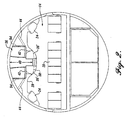
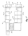
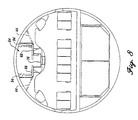
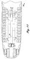
- FIGURE 1 shows a diagrammatic cross-section of an aircraft of the type with which the overhead attendant rest area in accordance with the present invention is intended to be used, in this case a Boeing 777.
- the aircraft 10 is of circular cross-section, a semimonocoque design having an outer skin supported on an inner peripheral frame.
- the floor 12 of the main cabin is disposed somewhat below the geometric center to provide a large passenger compartment 14 having the usual seating.
- the seating will include two outboard seat groups 18 and a center seat group 20, with aisles 22 between the outboard groups and the center group. While a 2-5-2 configuration of seating is shown, other configurations are possible, such as a 3-3-3 configuration, with reference to the number of seats in each group.
- the most efficient layout for a wide body aircraft having dual aisles necessitates the provision of a center seat group 20 along the centerline of the aircraft.
- the large passenger compartment 14 has outboard overhead storage compartments 24 (primarily for carry-ons), inboard storage compartments 26, and other amenities.
- the ceiling 28, storage bins 24 and 26, and any other ceiling mounted amenities or equipment are supported by an arrangement of structural ties 30 which are mounted in the crown of the aircraft, i.e., the area above the ceiling 28 of the passenger compartment, along with air-conditioning ducts 32.
- the lower lobe 34 of the aircraft accommodates standard cargo/baggage containers 28, as well as equipment bays, structural members and auxiliary equipment.
- an overhead rest area 36 is provided in the crown of the aircraft, above the ceiling 28 of the passenger cabin 14.
- the broken line 38 represents the contour of the central portion of the ceiling and overhead bin structure of the conventional aircraft shown in FIGURE 1.
- the ceiling is lowered at the center, such that there is room for a narrow aisle 40 with increased headroom.
- the rest area preferably includes bunks or beds 42 at opposite sides of the aisle which extends along the centerline of the aircraft. While the design does not affect the location or sizing of the outboard overhead bins 24, modified inboard overhead bins 26' of reduced size are located at opposite sides, respectively, of the lower portion of the aisle 40.
- the tapering of the ceiling down toward the center still allows sufficient headroom for passengers occupying the center seat group 20, and for ingress thereto and egress therefrom.
- the air-conditioning ducts and structural members that normally would occupy the central portion of the room must be relocated outboard or be integrated between bunks such that bunk spaces have no interferences.
- the main structural support for the rest area can be by ties 44 angled outward from the rest area to the aircraft frame.
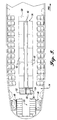
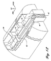
- access to the overhead rest area 36 can be by way of a stairway 46 in the aft portion of the aircraft, behind the last row of seating in the main passenger cabin 14, adjacent to the lavatories 48 and rear galley area 50, for example.
- the exact location of the stairway will depend on the location of permanent structure or monuments in the aircraft, such as the monument shown as the existing equipment bay 52. Thus, if a monument is designed for the starboard side of the aircraft, the stairway will be located on the port side, rather than on the starboard side as shown. It is preferred that a secure door 54 be provided for the stairway so that unauthorized personnel do not have access.
- the stairway can include a center landing 56 with lower stairs leading transversely to the landing, and an upper set of stairs leading from the landing to the aisle 40 between the beds 42.
- An additional stairway 58 can be provided at the forward portion of the overhead rest area.
- large side openings 60 provide convenient access to the beds 42, and privacy curtains can be provided for such openings.
- the layout lends itself to providing individual amenity modules 62 for the separate beds, which can include individually controlled lighting and ventilation nozzles, as well as communication equipment, and audio or visual alarms or call indicators.
- the layout provides regularly spaced intervals between individual bed modules for angled support members 44 (FIGURE 2) and/or vertical support members 94 (FIGURE 4) that coincide with regularly spaced intervals between sets of fuselage frames.
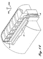
- the aft stairway 46' extends solely longitudinally of the aircraft.
- the starboard aft bed is removed, providing a widened passing area 63 in the aft portion of the longitudinally extending aisle 40. This may necessitate removing or at least decreasing the size of the overhead bin(s) in this area.
- a cross aisle 66 is provided toward the front of the modified rest area, with three side-by-side beds 42' located forward of the cross aisle. These beds necessarily have only end access, which is not as convenient as the side access provided for the side beds 42.
- the overhead rest area can be provided in modules so that additional sets or fewer sets of beds may be incorporated in a particular aircraft.
- one module can consist of a section equal to the length of a bed. The end walls of the bed units can be secured together during installation. These modules systematically incorporate the necessary structural and system interfaces allowing additional or fewer sets of beds.
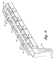
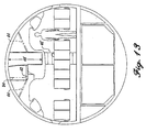
- the modular feature of the overhead rest area system in accordance with the present invention also lends itself to provision of other types of modules, such as a lounge module 64 as illustrated in FIGURES 6 and 7.
- FIGURE 6 shows a stairway 46' mounted in the aft area of the aircraft at the port side, rather than to starboard, and the lounge module 64 is the first module reached by way of the stairway.
- a settee or couch 66 can be provided along one side of the module, with special comfort seating 68 at the other side, such as recliners.
- the increased floor area also allows users of the overhead rest area to pass by each other, and the lounge module can include closets or other storage units 70.
- the modular nature of the lounge module is best seen in FIGURE 7, where the forward walls 72 are shown spaced rearward from the adjacent walls 74 of the next most forward module having a center aisle 40 and beds 42 at the sides.
- the increased transverse dimension of the lounge floor 76 will necessitate changes in the configuration of the inboard overhead bins.
- the lounge area provides a comfortable location for resting and talking while sitting, without using revenue producing seats in the main cabin of the aircraft.
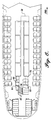
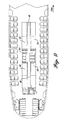
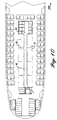
- the lounge area can be provided in the aft portion of the overhead resting area as shown in FIGURE 6 as shown in FIGURE 9, or toward the center, or at the forward portion of the resting area as shown in FIGURE 10.
- the center location of FIGURE 9 probably provides the most convenient passing location.
- each of the three aft modules consist of beds 42 at opposite sides of the center aisle 40.
- the next most forward module also has beds 42 at the opposite sides, but another bed 42" is fitted between the forwardmost side beds 42, and shifted forward relative to those beds.
- Doors or removable walls 75 separate the center forward bed 42" from another modular area which can include storage bins 78 for power supplies, video projection units or other equipment.
- FIGURE 12 and FIGURE 13 an aisle offset toward one side of the aircraft may be provided, particularly if a smaller resting area with only a few beds is required.
- the overhead resting area shown in FIGURES 12 and 13 has a stairway 46' aligned with a lowered aisle 40' offset toward the port side of the aircraft, and with raised beds 42 along the starboard side of the aisle.
- two additional side-by-side beds 80 are provided, the bed on the starboard side being accessible by a short raised cross aisle 82.
- the lowered aisle 40' necessary to provide adequate headroom for moving through the rest area, forces the elimination of overhead bins from one side of the center unit of the main cabin, but a full-size overhead bin can be provided at the other side.
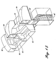
- FIGURES 15 and 16 uses an aisle 40' offset toward one side of the aircraft, in this case the port side, accessible by an aft stairway 46'.
- the aisle 40' provides access to longitudinally extending bunks 42 at the port side, and a longitudinally extending bed 42 at the center of the starboard side, which is sandwiched between transversely extending beds 84. Beds 84 would have end access.
- a widened passing area 90 is provided, adjacent to a forward bed 92 which is approximately centered in the aircraft.
- this arrangement will necessitate removing the overhead bins from one side of the center overhead storage area, and may provide too great an obstruction to longitudinally extending air conditioning ducts or other components to be practical for some aircraft. Nevertheless, as in all embodiments of the invention, seating in the main passenger cabin 14 or cargo/baggage capability in the lower lobe is minimally affected, so that the revenue generating capability of the aircraft is maximized, while still providing a convenient and comfortable rest area for attendants and pilots.
- FIGURE 17 illustrates the applicability to a larger aircraft of ovoid cross-section.
- Overhead attendant rest space 36 has adequate headroom for the long narrow aisleway 40 in the crown so that the stowbins 26 are retained in their original positions.
Landscapes
- Engineering & Computer Science (AREA)
- Aviation & Aerospace Engineering (AREA)
- Seats For Vehicles (AREA)
- Residential Or Office Buildings (AREA)
Claims (28)
- Aéronef (10) de transport de passagers ayant un fuselage qui contient une cabine principale (14) de passagers ayant une zone de sièges destinée à contenir des passagers assis, la cabine principale (14) des passagers ayant une structure à coffres de rangement espacée au-dessus des zones de sièges, et qui est directement accessible aux passagers de la cabine principale des passagers pour le transport de bagages à main, caractérisé en ce que :la structure à coffres de rangement comprend une zone suspendue de repos (36) ayant un accès depuis la cabine principale des passagers et qui est placée du côté supérieur de la structure à coffres de rangement, etla zone suspendue de repos (36) a un plancher incorporé dans la structure à coffres de rangement et plusieurs unités de repos (42).
- Aéronef selon la revendication 1, dans lequel la zone des sièges de la cabine principale des passagers comporte deux groupes externes de sièges et un groupe central de sièges, chacun des groupes externes de sièges étant séparé du groupe central de sièges par une allée dans la cabine principale des passagers, la structure à coffres de rangement comprenant une partie centrale disposée au-dessus du groupe central de sièges, l'allée de la zone suspendue de repos étant incorporée dans la partie centrale de la structure à coffres de rangement, et la structure à coffres de rangement comprenant au moins un coffre de rangement accessible depuis la cabine principale des passagers et disposé le long de la partie inférieure de l'allée de la zone suspendue de repos.
- Aéronef selon la revendication 1, dans lequel l'allée de la zone suspendue de repos s'étend suivant la longueur de l'aéronef.
- Aéronef selon la revendication 3, dans lequel l'allée s'étend approximativement au centre de l'aéronef.
- Aéronef selon la revendication 1, dans lequel les unités de repos comprennent plusieurs lits surélevés par rapport au plancher de l'allée de la zone suspendue de repos et s'étendant bout à bout dans la direction longitudinale de l'aéronef.
- Aéronef selon la revendication 1, dans lequel les unités de repos comprennent plusieurs lits qui s'étendent dans la direction longitudinale de l'aéronef sur des côtés opposés de l'allée de la zone suspendue de repos.
- Aéronef selon la revendication 1, dans lequel la structure à coffres de rangement comprend les coffres de rangement placés sur les côtés opposés de la partie inférieure de l'allée de la zone suspendue de repos, les coffres de rangement étant accessibles aux passagers de la zone de sièges de la cabine principale des passagers.
- Aéronef selon la revendication 1, dans lequel les unités de repos comprennent des lits surélevés au-dessus du plancher de l'allée de la zone suspendue de repos.
- Aéronef selon la revendication 1, dans lequel la structure des coffres de rangement est abaissée dans la zone de repos pour laisser une plus grande hauteur dans l'allée de la zone suspendue de repos.
- Aéronef selon la revendication 1, dans lequel les unités de repos sont disposées en modules, l'un des modules au moins ayant une partie centrale abaissée formant la partie inférieure de l'allée de la zone suspendue de repos, et des lits disposés longitudinalement et surélevés par rapport au plancher de l'allée et disposés de part et d'autre de celle-ci.
- Aéronef selon 1a revendication 1, dans lequel l'allée de la zone suspendue de repos a une longue partie étroite qui s'étend dans la direction longitudinale de l'aéronef sur la plus grande partie de sa longueur et une zone de passage de largeur accrue.
- Aéronef selon la revendication 1, dans lequel l'allée de la zone suspendue de repos s'étend dans la direction longitudinale de l'aéronef sur la plus grande partie de la longueur de l'allée, et comporte une allée transversale recoupant l'allée longitudinale, et plusieurs unités de repos adjacentes à l'allée transversale.
- Aéronef selon la revendication 12, dans lequel les unités de repos adjacentes à l'allée transversale comportent plusieurs lits ayant un accès par l'extrémité.
- Aéronef selon la revendication 1, dans lequel les unités de repos comportent des lits qui s'étendent dans la direction longitudinale sur des côtés opposés de l'allée de la zone suspendue de repos, et un module de salon ayant une zone de plancher de largeur accrue par rapport à la largeur de l'allée de la zone de repos.
- Aéronef selon la revendication 14, dans lequel les unités de repos comprennent plusieurs lits qui s'étendent dans la direction longitudinale le long de chaque côté de l'allée de la zone suspendue de repos, l'unité de salon étant placée entre les extrémités de la zone suspendue de repos avec des lits placés à la fois en avant et en arrière de cette unité de salon.
- Aéronef selon la revendication 1, dans lequel la zone suspendue de repos s'étend dans la direction longitudinale de l'aéronef, et comprend une unité à accès permanent à une première extrémité de la zone de repos.
- Aéronef selon la revendication 16, dans lequel l'unité d'accès est un escalier disposé dans la partie arrière de l'aéronef, en arrière de la zone de sièges de la cabine principale des passagers.
- Aéronef selon la revendication 1, dans lequel les unités de repos comprennent des lits qui s'étendent en direction longitudinale sur les côtés opposés de l'allée de la zone suspendue de repos, et un lit supplémentaire aligné approximativement sur l'allée de la zone suspendue de repos.
- Aéronef selon la revendication 18, comprenant une unité de rangement adjacente au lit supplémentaire et accessible depuis celui-ci, l'unité de rangement étant disposée au-dessus de la zone de sièges de la cabine principale des passagers.
- Aéronef selon la revendication 1, dans lequel l'allée s'étend dans la direction longitudinale de l'aéronef en étant décalée par rapport à l'axe central de celui-ci, et les unités de repos comprennent plusieurs lits s'étendant dans la direction longitudinale d'un côté de l'allée de la zone suspendue de repos.
- Aéronef selon la revendication 20, dans lequel les unités de repos comprennent des lits supplémentaires disposés en avant des lits qui s'étendent dans la direction longitudinale, l'un des lits supplémentaires étant approximativement aligné sur l'allée de la zone suspendue de repos.
- Aéronef selon la revendication 20, dans lequel la structure à coffres de rangement comprend des coffres de rangement accessibles depuis la cabine principale des passagers et disposés uniquement d'un seul côté de la partie inférieure de l'allée de la zone suspendue de repos.
- Aéronef selon la revendication 1, dans lequel les unités de repos comportent des lits qui s'étendent transversalement à l'aéronef et ayant un accès par l'extrémité depuis l'allée de la zone suspendue de repos.
- Aéronef selon la revendication 1, dans lequel les unités de repos comportent des lits qui s'étendent dans la direction longitudinale de l'aéronef et ayant un accès latéral depuis l'allée de la zone suspendue de repos, et des lits qui s'étendent transversalement à l'aéronef et ayant un accès par l'extrémité depuis l'allée de la zone suspendue de repos.
- Aéronef selon la revendication 1, dans lequel le fuselage comporte une ossature périphérique, la zone suspendue de repos étant supportée par la partie supérieure de l'ossature.
- Aéronef selon la revendication 25, dans lequel la structure à coffres de rangement est supportée à la zone suspendue de repos.
- Aéronef selon la revendication 26, dans lequel la zone suspendue de repos est supportée au moins en partie par des tirants verticaux.
- Aéronef selon la revendication 26, dans lequel la zone suspendue de repos est supportée au moins en partie par des tirants qui s'étendent vers l'extérieur et vers le haut depuis la zone suspendue de repos vers l'ossature périphérique.
Applications Claiming Priority (10)
| Application Number | Priority Date | Filing Date | Title |
|---|---|---|---|
| US5833297P | 1997-09-10 | 1997-09-10 | |
| US5834597P | 1997-09-10 | 1997-09-10 | |
| US5848597P | 1997-09-10 | 1997-09-10 | |
| US5834497P | 1997-09-10 | 1997-09-10 | |
| US58345P | 1997-09-10 | ||
| US58332P | 1997-09-10 | ||
| US58344P | 1997-09-10 | ||
| US58485P | 1997-09-10 | ||
| US144407P | 1998-08-31 | ||
| US09/144,407 US6073883A (en) | 1997-09-10 | 1998-08-31 | Aircraft overhead rest areas |
Publications (3)
| Publication Number | Publication Date |
|---|---|
| EP0901964A2 EP0901964A2 (fr) | 1999-03-17 |
| EP0901964A3 EP0901964A3 (fr) | 1999-10-27 |
| EP0901964B1 true EP0901964B1 (fr) | 2002-07-03 |
Family
ID=27535429
Family Applications (1)
| Application Number | Title | Priority Date | Filing Date |
|---|---|---|---|
| EP98203036A Expired - Lifetime EP0901964B1 (fr) | 1997-09-10 | 1998-09-10 | Avion à aires de repos suspendus |
Country Status (3)
| Country | Link |
|---|---|
| US (1) | US6073883A (fr) |
| EP (1) | EP0901964B1 (fr) |
| DE (1) | DE69806314T2 (fr) |
Cited By (1)
| Publication number | Priority date | Publication date | Assignee | Title |
|---|---|---|---|---|
| JP2008507448A (ja) * | 2004-07-26 | 2008-03-13 | エアバス | 航空機の客室上部空間の改造 |
Families Citing this family (64)
| Publication number | Priority date | Publication date | Assignee | Title |
|---|---|---|---|---|
| DE69923925T2 (de) | 1998-12-14 | 2006-02-23 | The Boeing Co., Seattle | Unterkunftseinheiten im oberen Bereich der Flugzeugkabine |
| US6464169B1 (en) * | 2001-07-27 | 2002-10-15 | The Boeing Company | Overhead galley/crew rest facility |
| ATE514593T1 (de) | 2001-08-09 | 2011-07-15 | Virgin Atlantic Airways Ltd | Eine sitzeinheit für ein fahrzeug |
| US6616098B2 (en) | 2001-08-13 | 2003-09-09 | The Boeing Company | Mid-level deck for passenger aircraft |
| US6659225B2 (en) * | 2001-09-13 | 2003-12-09 | The Boeing Company | Stairway for enabling access to an overhead area within a fuselage of an aircraft |
| US6536710B1 (en) * | 2002-02-06 | 2003-03-25 | The Boeing Company | Overhead lattice support structure |
| US6848654B1 (en) | 2004-01-09 | 2005-02-01 | The Boeing Company | Modular offset aisle overhead crew rest |
| US7389959B2 (en) * | 2004-01-19 | 2008-06-24 | The Boeing Company | Modular overhead privacy system and method |
| US6932298B1 (en) * | 2004-01-19 | 2005-08-23 | The Boeing Company | Modular overhead privacy system |
| US7080806B2 (en) * | 2004-03-26 | 2006-07-25 | The Boeing Company | Overhead space access conversion monument and service area staircase and stowage system |
| US7159821B2 (en) * | 2004-04-02 | 2007-01-09 | The Boeing Company | Integrated transport system for overhead stowage |
| US6971608B2 (en) * | 2004-04-02 | 2005-12-06 | The Boeing Company | Integrated transport system and method for overhead stowage and retrieval |
| CA2573971C (fr) | 2004-07-26 | 2013-07-02 | Airbus | Amenagement de la partie superieure de la cabine d'un aeronef |
| US7201349B2 (en) * | 2004-09-09 | 2007-04-10 | Airbus | Medical unit in an aircraft |
| US7083145B2 (en) * | 2004-09-24 | 2006-08-01 | The Boeing Company | Crew rest module and method of forming same |
| US7237749B2 (en) * | 2004-12-14 | 2007-07-03 | The Boeing Company | Collapsible mobile platform interior structure |
| US7494091B2 (en) | 2005-02-22 | 2009-02-24 | The Boeing Company | Aircraft cart transport and stowage system |
| FR2886622B1 (fr) * | 2005-06-02 | 2007-07-20 | Airbus France Sas | Avion long-courrier |
| US7721990B2 (en) * | 2005-07-29 | 2010-05-25 | Airbus Deutschland Gmbh | Passenger compartment |
| DE102005048709A1 (de) * | 2005-10-12 | 2007-04-26 | Airbus Deutschland Gmbh | Vertikal beweglicher Gang für Ruheräume im Deckenbereich |
| US7717371B2 (en) * | 2006-01-25 | 2010-05-18 | Airbus Deutschland Gmbh | Resting deck in an aircraft with resting cabins |
| FR2903664B1 (fr) | 2006-07-12 | 2008-09-26 | Airbus France Sas | Amenagement de cabine d'aeronef presentant des couchettes dans la partie superieure de la cabine. |
| FR2911114B1 (fr) * | 2007-01-10 | 2009-02-27 | Airbus France Sas | Cockpit securise pour aeronef |
| DE102007009279A1 (de) | 2007-02-26 | 2008-08-28 | Airbus Deutschland Gmbh | Modul zum Aufenthalt von Besatzungsmitgliedern mit Arbeitsbereich |
| EP2125514B1 (fr) * | 2007-02-26 | 2013-12-11 | Airbus Operations GmbH | Module pour le logement des membres d'équipage doté d'un coffre d'arrimage utilisable de l'intérieur du module |
| DE102007009278B4 (de) | 2007-02-26 | 2015-02-19 | Airbus Operations Gmbh | Aufenthalts-Modul mit durch die Crew nutzbarer Gepäckfachablage |
| DE102007009280A1 (de) | 2007-02-26 | 2008-08-28 | Airbus Deutschland Gmbh | Modul zum Aufenthalt von Besatzungsmitgliedern mit vollständig integriertem Gepäckablagefach-Stauraum |
| DE102007035681A1 (de) * | 2007-07-30 | 2009-02-05 | Airbus Deutschland Gmbh | Aufenthalts- und Schlafmodul zur Unterbringung von zumindest einem Mitglied einer Flugzeugbesatzung mit einem andockbaren Teilmodul |
| EP2062816A1 (fr) * | 2007-11-20 | 2009-05-27 | Airbus Deutschland GmbH | Module de repos comprenant un premier élément offrant un accès direct à un deuxième élément |
| DE102008015788A1 (de) | 2008-03-26 | 2009-10-08 | Airbus Deutschland Gmbh | Ergonomische und platzsparende Anordnung von Monumenten unter einem Ruheraum in einem Flugzeug |
| FR2929244B1 (fr) * | 2008-03-27 | 2010-07-30 | Airbus | Espace de travail et de rangement a l'arriere d'une cabine d'aeronef |
| DE102008016418A1 (de) * | 2008-03-31 | 2009-10-01 | Airbus Deutschland Gmbh | Entkopplungstechnik des Stairhouses zum Overhead Compartment |
| DE102008020789A1 (de) | 2008-04-25 | 2009-11-05 | Airbus Deutschland Gmbh | Befestigungssystem sowie Verfahren zum Befestigen eines Elementes einer Flugzeuginnenausstattung |
| USD643797S1 (en) * | 2009-07-16 | 2011-08-23 | The Boeing Company | Passenger sleeper cabin |
| US8991756B2 (en) * | 2009-12-14 | 2015-03-31 | Be Intellectual Property, Inc. | Small diameter pressure structure commercial aircraft crew rest |
| CN102762455B (zh) * | 2010-02-19 | 2016-05-18 | 空中客车德国运营有限责任公司 | 用于交通工具的盥洗室装置 |
| US9452817B1 (en) | 2010-03-03 | 2016-09-27 | The Boeing Company | Aircraft having split level cabin floors |
| US9108719B2 (en) | 2010-03-03 | 2015-08-18 | The Boeing Company | Aircraft with AFT split-level multi-deck fusealge |
| US10589836B2 (en) | 2010-03-03 | 2020-03-17 | The Boeing Company | Split level forward double deck airliner |
| CA2850038A1 (fr) | 2011-10-07 | 2013-04-11 | Bombardier Inc. | Banquette d'avion convertible en couchette |
| EP2844557B1 (fr) | 2012-05-04 | 2019-07-10 | Bombardier Inc. | Agencement de sièges convertible en couchette |
| US9308995B2 (en) * | 2012-08-24 | 2016-04-12 | Greenpoint Technologies, Inc. | Overhead space utilization device |
| AT513939A1 (de) * | 2013-02-01 | 2014-08-15 | Facc Ag | Überkopf-Gepäckfach für Flugzeuge und Flugzeug mit solchen Überkopf-Gepäckfächern |
| US9643724B2 (en) | 2013-09-11 | 2017-05-09 | Driessen Aerospace Group N.V. | Aircraft galley configuration |
| EP2894136B1 (fr) | 2014-01-08 | 2019-12-04 | The Boeing Company | Procédé amélioré de fabrication de panneaux intérieurs durables et ignifuges pour avions |
| US10891504B2 (en) * | 2014-06-13 | 2021-01-12 | Rockwell Collins, Inc. | Passenger rest compartments for remote aircraft spaces |
| US10909397B2 (en) | 2014-06-13 | 2021-02-02 | B/E Aerospace, Inc. | Aircraft suite including main cabin compartment and lower lobe rest compartment |
| US10891505B2 (en) | 2014-06-13 | 2021-01-12 | Rockwell Collins, Inc. | Bidirectional entry vestibule for aircraft passenger rest cabins |
| DE102015102315A1 (de) * | 2015-02-18 | 2016-08-18 | Airbus Operations Gmbh | Anordnung in einer Kabine eines Fahrzeugs mit in flächigem Kontakt ihrer Seitenflächen aneinander reihbaren Kabinenmonumenten |
| US9708065B2 (en) | 2015-04-07 | 2017-07-18 | The Boeing Company | Crown cabin configuration for an aircraft |
| EP3263444B1 (fr) * | 2016-06-30 | 2020-04-01 | Cathay Pacific Airways Limited | Module de cabine et agencement pour un aéronef de passagers |
| US20180016012A1 (en) * | 2016-07-12 | 2018-01-18 | B/E Aerospace, Inc. | System, Methods, and Apparatus for Air Flow Handling in an Aircraft Monument |
| WO2020112203A1 (fr) * | 2018-09-10 | 2020-06-04 | Rockwell Collins, Inc. | Cabines de repos pour passagers pour espaces d'aéronefs distants |
| US11167850B2 (en) * | 2018-09-10 | 2021-11-09 | Rockwell Collins, Inc. | Passenger friendly overhead rest cabin configuration |
| US11136137B2 (en) * | 2018-09-10 | 2021-10-05 | Rockwell Collins, Inc. | Non-intrusive passenger rest cabin monitoring system |
| US11235852B2 (en) | 2018-09-10 | 2022-02-01 | B/E Aerospace, Inc. | Bidirectional hatch for passenger rest compartment |
| US11447250B2 (en) | 2018-09-10 | 2022-09-20 | Rockwell Collins, Inc. | Optimized configuration for lower lobe passenger rest cabins |
| US10807716B2 (en) | 2018-09-18 | 2020-10-20 | The Boeing Company | Overhead payload module with integrated stowbins |
| US10850845B2 (en) | 2018-09-18 | 2020-12-01 | The Boeing Company | Overhead payload module with integrated stowbins |
| JP1684497S (fr) * | 2020-02-20 | 2021-05-10 | ||
| US11767117B2 (en) * | 2021-01-06 | 2023-09-26 | Toyota Boshoku Kabushiki Kaisha | Room for aircraft cabin |
| US11772798B2 (en) | 2022-02-07 | 2023-10-03 | B/E Aerospace, Inc. | Aircraft monument with integrated cabin crew quarters |
| US20240359795A1 (en) * | 2023-04-25 | 2024-10-31 | The Boeing Company | Crew rest system for an internal cabin of an aircraft |
| US20250042548A1 (en) * | 2023-07-31 | 2025-02-06 | Young Seo CHO | Seat system for airplane |
Family Cites Families (7)
| Publication number | Priority date | Publication date | Assignee | Title |
|---|---|---|---|---|
| US2081529A (en) * | 1936-01-02 | 1937-05-25 | Boeing Aircraft Co | Airplane sleeping berth arrangement |
| US4066227A (en) * | 1976-07-16 | 1978-01-03 | Buchsel Christian K E | Mezzanine structure for wide-bodied passenger aircraft |
| GB2169256B (en) * | 1985-01-08 | 1988-05-25 | Viktoria Georgievn Tereschenko | Aircraft cabin |
| SE452445B (sv) * | 1986-12-30 | 1987-11-30 | Wolfgang Paul Platzer | Anordning for passagerare i mobila enheter |
| DE4416506C2 (de) * | 1994-05-10 | 1999-12-02 | Daimler Chrysler Aerospace | Passagierflugzeug |
| US5784836A (en) * | 1994-11-03 | 1998-07-28 | Be Aerospace, Inc. | Demountable comfort modules for passenger aircraft |
| US5697580A (en) * | 1995-09-25 | 1997-12-16 | The United States Of America As Represented By The Secretary Of Transportation | Infant transporting means for airplanes |
-
1998
- 1998-08-31 US US09/144,407 patent/US6073883A/en not_active Expired - Lifetime
- 1998-09-10 DE DE69806314T patent/DE69806314T2/de not_active Expired - Lifetime
- 1998-09-10 EP EP98203036A patent/EP0901964B1/fr not_active Expired - Lifetime
Cited By (2)
| Publication number | Priority date | Publication date | Assignee | Title |
|---|---|---|---|---|
| JP2008507448A (ja) * | 2004-07-26 | 2008-03-13 | エアバス | 航空機の客室上部空間の改造 |
| JP4870668B2 (ja) * | 2004-07-26 | 2012-02-08 | エアバス | 航空機の客室上部空間の改造 |
Also Published As
| Publication number | Publication date |
|---|---|
| DE69806314D1 (de) | 2002-08-08 |
| EP0901964A2 (fr) | 1999-03-17 |
| DE69806314T2 (de) | 2002-10-17 |
| US6073883A (en) | 2000-06-13 |
| EP0901964A3 (fr) | 1999-10-27 |
Similar Documents
| Publication | Publication Date | Title |
|---|---|---|
| EP0901964B1 (fr) | Avion à aires de repos suspendus | |
| EP0901962B1 (fr) | Système d'évacuation pour zones de repos dans les cabines d'avions | |
| US9550571B1 (en) | Overhead accommodations for aircraft | |
| US7252268B2 (en) | Interior configuration for an aircraft cabin | |
| EP0901963B2 (fr) | Compartiments à couchettes dans la soute à fret d'un avion | |
| US6616098B2 (en) | Mid-level deck for passenger aircraft | |
| US5752673A (en) | Passenger aircraft with increased passenger capacity | |
| US5784836A (en) | Demountable comfort modules for passenger aircraft | |
| EP3718892B1 (fr) | Agencements de suite de voyage en classe affaires pour aéronefs à fuselage étroit et large | |
| EP2512921B1 (fr) | Station de repos d'équipage d'avion commercial à structure à pression de petit diamètre | |
| US8882036B2 (en) | Aircraft seating arrangement | |
| US20080179457A1 (en) | Passenger aircraft | |
| US7389959B2 (en) | Modular overhead privacy system and method | |
| EP0987177A3 (fr) | Aéronef à double cabine supérieure | |
| US20170137109A1 (en) | Aircraft for the transport of passengers having lower deck facilities | |
| CN108382600B (zh) | 飞行器用的前内部空间布置 | |
| EP4223639B1 (fr) | Monument d'aéronef avec quartiers d'équipage de cabine intégrés | |
| AU2021225108B2 (en) | A multi-layer sleeping compartment |
Legal Events
| Date | Code | Title | Description |
|---|---|---|---|
| PUAI | Public reference made under article 153(3) epc to a published international application that has entered the european phase |
Free format text: ORIGINAL CODE: 0009012 |
|
| AK | Designated contracting states |
Kind code of ref document: A2 Designated state(s): DE FR GB |
|
| AX | Request for extension of the european patent |
Free format text: AL;LT;LV;MK;RO;SI |
|
| PUAL | Search report despatched |
Free format text: ORIGINAL CODE: 0009013 |
|
| AK | Designated contracting states |
Kind code of ref document: A3 Designated state(s): AT BE CH CY DE DK ES FI FR GB GR IE IT LI LU MC NL PT SE |
|
| AX | Request for extension of the european patent |
Free format text: AL;LT;LV;MK;RO;SI |
|
| 17P | Request for examination filed |
Effective date: 20000419 |
|
| AKX | Designation fees paid |
Free format text: DE FR GB |
|
| 17Q | First examination report despatched |
Effective date: 20001103 |
|
| GRAG | Despatch of communication of intention to grant |
Free format text: ORIGINAL CODE: EPIDOS AGRA |
|
| GRAG | Despatch of communication of intention to grant |
Free format text: ORIGINAL CODE: EPIDOS AGRA |
|
| GRAH | Despatch of communication of intention to grant a patent |
Free format text: ORIGINAL CODE: EPIDOS IGRA |
|
| GRAH | Despatch of communication of intention to grant a patent |
Free format text: ORIGINAL CODE: EPIDOS IGRA |
|
| GRAA | (expected) grant |
Free format text: ORIGINAL CODE: 0009210 |
|
| AK | Designated contracting states |
Kind code of ref document: B1 Designated state(s): DE FR GB |
|
| REF | Corresponds to: |
Ref document number: 69806314 Country of ref document: DE Date of ref document: 20020808 |
|
| ET | Fr: translation filed | ||
| PLBE | No opposition filed within time limit |
Free format text: ORIGINAL CODE: 0009261 |
|
| STAA | Information on the status of an ep patent application or granted ep patent |
Free format text: STATUS: NO OPPOSITION FILED WITHIN TIME LIMIT |
|
| 26N | No opposition filed |
Effective date: 20030404 |
|
| REG | Reference to a national code |
Ref country code: FR Ref legal event code: PLFP Year of fee payment: 19 |
|
| REG | Reference to a national code |
Ref country code: FR Ref legal event code: PLFP Year of fee payment: 20 |
|
| PGFP | Annual fee paid to national office [announced via postgrant information from national office to epo] |
Ref country code: GB Payment date: 20170927 Year of fee payment: 20 Ref country code: FR Payment date: 20170925 Year of fee payment: 20 |
|
| PGFP | Annual fee paid to national office [announced via postgrant information from national office to epo] |
Ref country code: DE Payment date: 20170927 Year of fee payment: 20 |
|
| REG | Reference to a national code |
Ref country code: DE Ref legal event code: R071 Ref document number: 69806314 Country of ref document: DE |
|
| REG | Reference to a national code |
Ref country code: GB Ref legal event code: PE20 Expiry date: 20180909 |
|
| PG25 | Lapsed in a contracting state [announced via postgrant information from national office to epo] |
Ref country code: GB Free format text: LAPSE BECAUSE OF EXPIRATION OF PROTECTION Effective date: 20180909 |