EP0901980A2 - Antrieb für Aufzüge - Google Patents
Antrieb für Aufzüge Download PDFInfo
- Publication number
- EP0901980A2 EP0901980A2 EP98116393A EP98116393A EP0901980A2 EP 0901980 A2 EP0901980 A2 EP 0901980A2 EP 98116393 A EP98116393 A EP 98116393A EP 98116393 A EP98116393 A EP 98116393A EP 0901980 A2 EP0901980 A2 EP 0901980A2
- Authority
- EP
- European Patent Office
- Prior art keywords
- drive according
- frame
- planetary gear
- rotor
- drive
- Prior art date
- Legal status (The legal status is an assumption and is not a legal conclusion. Google has not performed a legal analysis and makes no representation as to the accuracy of the status listed.)
- Granted
Links
Images


Classifications
-
- B—PERFORMING OPERATIONS; TRANSPORTING
- B66—HOISTING; LIFTING; HAULING
- B66B—ELEVATORS; ESCALATORS OR MOVING WALKWAYS
- B66B11/00—Main component parts of lifts in, or associated with, buildings or other structures
- B66B11/04—Driving gear ; Details thereof, e.g. seals
- B66B11/043—Driving gear ; Details thereof, e.g. seals actuated by rotating motor; Details, e.g. ventilation
- B66B11/0453—Driving gear ; Details thereof, e.g. seals actuated by rotating motor; Details, e.g. ventilation with planetary or epicycloidal gear, e.g. differential gear
Definitions
- the invention relates to a drive for elevators with a electromotive driven traction sheave and busy deal with the problem of making such a drive as small as possible building and working with a high degree of efficiency.
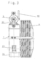
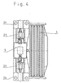
- the main components of the elevator drive are a frame 1, a unit stored in this from a synchronous motor 2 and a two-stage planetary gear 3, one with the Output of the planetary gear connected traction sheave 4 and a shoe brake attached to the frame 1 on the drive side 5.
- the one consisting of the synchronous motor 2 and the planetary gear 3 The unit has the housing of the planetary gear as a common carrier.
- the housing of the planetary gear 3 is flanged to the side of the frame 1, the flange the gearbox with screws 6 firmly to the frame 1 connected is.
- the synchronous motor 2 is a permanent magnet excited AC synchronous motor. This is composed from a rotor 7, which has permanent magnets on its circumferential surface 8 is equipped and from a rotor 7 radially encompassing stator 11 in which the electrical coils 10 are stored.
- the material of the stator housing 9 is aluminum. Connected to the housing of the planetary gear 3 is the stator housing 9 via screws 12.
- the rotor 7 is axially aligned on the drive shaft 13 of the planetary gear 3 pushed on and firmly connected to it.
- the bearing of the drive shaft 13 together with the rotor 7 takes place within the housing of the planetary gear 3 in a common camp 14.
- the rotating part of a resolver 16 for the synchronous motor 2 is on the end facing away from the planetary gear 3 3 of the rotor 7 firmly connected.
- the immovable part of the resolver 16 is screwed onto a turntable 18.
- the turntable 18 is rotatably mounted in the frame 1 and in any rotational position using the screws 19 provided there fixable.
- a brake disc 20 Firmly connected to the rotor 7 and rotating coaxially with it is a brake disc 20, the outer circumferential ring wall surrounds the stator housing 9 radially.
- the brake 5 is with a Unlocking lever 22 is provided, which can be remotely operated.
- the brake shoes 21 can interact with a level switch, to on the basis of the pivot position of the brake shoes 21 when tightened Brake over wear of the brake pads to be able to determine the specified dimension.
- the stator housing 9 is transverse over a conical circumference slotted clamping ring 23 in a receiving ring area of the frame 1 firmly clamped. As a result, a good heat conduction from the stator housing 9 into the frame 1 respectively. In this way, the frame 1 also receives one Cooler function.
- the frame 1 is above and below, respectively provided with mounting flanges 24, in particular can be carried out in the same way. Through these flanges 24 are different fastening options in the elevator system possible.
Landscapes
- Engineering & Computer Science (AREA)
- Civil Engineering (AREA)
- Mechanical Engineering (AREA)
- Structural Engineering (AREA)
- Cage And Drive Apparatuses For Elevators (AREA)
- Connection Of Motors, Electrical Generators, Mechanical Devices, And The Like (AREA)
- Vending Machines For Individual Products (AREA)
- Liquid Crystal (AREA)
- Air-Conditioning For Vehicles (AREA)
Abstract
Description
- Durch die Verwendung eines Planetengetriebes, das mehrstufig ausgebildet sein kann, kann ein kleinbauender und einen hohen Wirkungsgrad aufweisender mit hohen Drehzahlen arbeitender Synchronmotor eingebaut werden, da das an der Treibscheibe aufzubringende hohe Drehmoment durch eine in dem Planetengetriebe erfolgende hohe Drehzahlübersetzung ins Langsame aufgebracht werden kann. Aufgrund eines erreichbaren besonders hohen Wirkungsgrades arbeitet der erfindungsgemäße Antrieb äußerst energiesparend.
- Die Integration des Synchronmotors in das Planetengetriebe erlaubt eine insbesondere kurze Baulänge des Antriebes.
- Die Integration der Bremsscheibe in den Motorbereich trägt einerseits zusätzlich zu einer kurzen Baulänge bei und ermöglicht andererseits durch die antriebsseitige Anordnung der Bremse wegen der dort noch geringen Drehmomente eine kleine Baugröße dieser Bremse.
- Es können Treibscheiben in üblichen Formen und Größen eingesetzt werden. Die Treibscheibe kann mit ihrem das Aufzugsseil führenden Ringbereich das Planetengetriebe radial umfassen. Durch diese Anordnung ist eine günstige Lagerbelastung innerhalb des Planetengetriebes für den Getriebeabtrieb möglich.
- Der Motor und das Getriebe des Antriebes bilden eine Einheit, die austauschbar in einen Rahmen des Antriebes befestigbar ist.
- Über den Antriebs-Rahmen kann Wärme des Synchronmotors abgeleitet werden, wodurch der Rahmen als Kühlkörper wirkt.
- Es ist eine einfache Lagerung und Einstellung des Resolvers des Synchronmotors möglich.
- Aufgrund der erreichbaren kleinen Baugröße sind mit Hilfe des Rahmens des Antriebes verschiedenartige Anbaumöglichkeiten gegeben, wie beispielsweise eine sogenannte Fußbefestigung innerhalb der Konstruktion des Aufzugsschachtes oder eine direkte Befestigung an der Fahrschiene der Aufzugsanlage.
- Durch ein modulares Baukonzept ist das Getriebe leicht auswechselbar.
- Für einen Notbetrieb der Aufzugsanlage ist kein Zusatzantrieb notwendig, da der Synchronmotor wegen des von ihm aufzubringenden geringen Drehmomentes batteriebetriebsfähig ist.
- Der Rotor des Synchronmotors ist gemeinsam mit der Getriebeantriebswelle gelagert, wodurch Lager eingespart werden können.
- Fig. 1
- eine Ansicht eines Aufzugs-Antriebes,
- Fig. 2
- einen Schnitt nach Linie II-II durch den Antrieb nach Fig. 1,
- Fig. 3
- eine Seitenansicht des Antriebes,
- Fig. 4
- eine Draufsicht auf den Antrieb.
Claims (13)
- Antrieb für Aufzüge mit einer elektromotorisch angetriebenen Treibscheibe,
dadurch gekennzeichnet,
daß die Treibscheibe (4) von einem permanentmagneterregten Synchronmotor (2) über ein Planetengetriebe (3) angetrieben wird. - Antrieb nach Anspruch 1,
dadurch gekennzeichnet,
daß ein permanentmagnetbestückter Rotor (7) des Synchronmotors (2) achsgleich zu einer Antriebswelle (13) des Planetengetriebes (3) angeordnet und fest mit dieser verbunden ist. - Antrieb nach Anspruch 1 oder 2,
dadurch gekennzeichnet,
daß der Rotor (7) und die Getriebe-Antriebswelle (13) gemeinsam gelagert sind. - Antrieb nach Anspruch 3,
dadurch gekennzeichnet,
daß die gemeinsame Lagerung ausschließlich in dem Gehäuse des Planetengetriebes (3) vorgesehen ist. - Antrieb nach einem der vorhergehenden Ansprüche,
dadurch gekennzeichnet,
daß der Rotor (7) auf seinem Außenumfang permanentmagnetbestückt ist und innerhalb eines mit elektrischen Spulen (10) versehenen Ringes als Stator (11) rotiert. - Antrieb nach einem der vorhergehenden Ansprüche,
dadurch gekennzeichnet,
daß das Statorgehäuse (9) fest mit dem Gehäuse des Planetengetriebes (3) verbunden ist. - Antrieb nach einem der vorhergehenden Ansprüche,
dadurch gekennzeichnet,
daß die elektrischen Spulen (10) des Stators (11) in einem optimal wärmeableitenden Statorgehäuse (9) aus Aluminium angeordnet sind. - Antrieb nach einem der vorhergehenden Ansprüche,
dadurch gekennzeichnet,
daß die von dem Planetengetriebe (3) abgewandte Stirnseite des Rotors (7) mit einer topfförmigen Ring-Bremsscheibe (20) verbunden ist, deren Ringwand das Statorgehäuse (9) radial umfaßt. - Antrieb nach einem der vorhergehenden Ansprüche,
dadurch gekennzeichnet,
daß eine aus Synchronmotor (2) und Planetengetriebe (3) gebildete Einheit lösbar in einem diese Einheit radial umschließenden Rahmen (1) befestigt ist und daß in dem Rahmen (1) die feststehenden Teile einer Backen-Bremse (5) gelagert sein können, deren schwenkbare Backen (21) mit der Bremsscheibe (20) zusammenwirken. - Antrieb nach einem der vorhergehenden Ansprüche,
dadurch gekennzeichnet,
daß ein Resolver (16) des Synchronmotors (2) im freien Zentrum der ringförmigen Bremsscheibe (20) liegt, wobei dessen rotierender Teil (15) fest mit dem Rotor (7) und dessen feststehender Teil (17) mit dem Rahmen (1) verbunden ist, wobei die feste Verbindung in dem Rahmen (1) in beliebiger Drehstellung der fixierbaren Drehscheibe (18) erfolgen kann. - Antrieb nach einem der vorhergehenden Ansprüche,
dadurch gekennzeichnet,
daß die Motor-Getriebe-Einheit getriebeseitig axial an den Rahmen (1) angeflanscht ist und daß ein konischer, axial verspannter Klemmring (23), der am Umfang quergeschlitzt ist, das Statorgehäuse (9) innerhalb des Rahmens (1) radial formschlüssig einspannt, um eine gute Wärmeableitung zu ermöglichen. - Antrieb nach einem der vorhergehenden Ansprüche,
dadurch gekennzeichnet,
daß der Rahmen (1) mit mehreren Befestigungsflanschen (24) für unterschiedliche Befestigungsmöglichkeiten des Rahmens (1) an einem Aufnahmekörper der Aufzugsanlage versehen ist und daß die Treibscheibe (4) topfförmig ausgebildet sein und mit ihrer das Aufzugsseil führenden Ringwand das Planetengetriebe (3) radial umgreifen kann. - Antrieb nach einem der vorhergehenden Ansprüche,
dadurch gekennzeichnet,
daß die Backen-Bremse (5) mit einer Kontrolleinrichtung für das Feststellen des Bremsbelagverschleißes versehen ist und/oder fernbedient entriegelbar ist.
Applications Claiming Priority (2)
| Application Number | Priority Date | Filing Date | Title |
|---|---|---|---|
| DE19739899A DE19739899A1 (de) | 1997-09-11 | 1997-09-11 | Antrieb für Aufzüge |
| DE19739899 | 1997-09-11 |
Publications (3)
| Publication Number | Publication Date |
|---|---|
| EP0901980A2 true EP0901980A2 (de) | 1999-03-17 |
| EP0901980A3 EP0901980A3 (de) | 2000-11-15 |
| EP0901980B1 EP0901980B1 (de) | 2004-08-04 |
Family
ID=7841986
Family Applications (1)
| Application Number | Title | Priority Date | Filing Date |
|---|---|---|---|
| EP98116393A Expired - Lifetime EP0901980B1 (de) | 1997-09-11 | 1998-08-29 | Antrieb für Aufzüge |
Country Status (3)
| Country | Link |
|---|---|
| EP (1) | EP0901980B1 (de) |
| AT (1) | ATE272565T1 (de) |
| DE (2) | DE19739899A1 (de) |
Cited By (5)
| Publication number | Priority date | Publication date | Assignee | Title |
|---|---|---|---|---|
| EP1028081A3 (de) * | 1999-02-10 | 2001-02-28 | Ziehl-Abegg GmbH & Co.KG | Aufzugsantrieb mit elektrischem Antriebsmotor |
| EP1172322A1 (de) * | 2000-07-14 | 2002-01-16 | Miguel Manuel Zarraga Valpuesta | Antriebssystem für Kabeltrommeln |
| WO2009075672A1 (en) * | 2007-12-10 | 2009-06-18 | Otis Elevator Company | Integrated elevator machine motor and drive |
| WO2009151434A1 (en) * | 2008-06-09 | 2009-12-17 | Otis Elevator Company | Elevator machine motor and drive and cooling thereof |
| CN102107811A (zh) * | 2009-12-28 | 2011-06-29 | 上海永大吉亿电机有限公司 | 用于电梯或电扶梯的牵引机 |
Families Citing this family (3)
| Publication number | Priority date | Publication date | Assignee | Title |
|---|---|---|---|---|
| US6892862B2 (en) | 2000-07-29 | 2005-05-17 | Alpha Getriebebau Gmbh | Elevator car with a driving pulley driving machine integrated therein |
| DE10259426A1 (de) * | 2002-12-06 | 2004-06-24 | Prodema Antriebstechnik Gmbh & Co. Kg | Gleichstrommotor, insbesondere für maritime Zwecke |
| EP2497739A1 (de) | 2011-03-10 | 2012-09-12 | Hansruedi Diethelm | Aufzug |
Family Cites Families (9)
| Publication number | Priority date | Publication date | Assignee | Title |
|---|---|---|---|---|
| DE1684759U (de) * | 1954-07-27 | 1954-10-07 | Schmitt & Sohn Aufzugwerke | Antriebsvorrichtung fuer aufzuege. |
| DE1288773B (de) * | 1967-10-18 | 1969-02-06 | Alois Kasper Hebezeugfabrik | Aufzugsgetriebe mit Aussenlaeufermotor |
| JPS58113084A (ja) * | 1981-12-28 | 1983-07-05 | 三菱電機株式会社 | 駆動装置 |
| US5435209A (en) * | 1992-06-26 | 1995-07-25 | Wittur Aufzugteile Gmbh & Co. | Drive unit for a hoisting apparatus, in particular for a passenger or freight elevator |
| DE4323361A1 (de) * | 1993-07-13 | 1995-01-19 | Dewitta Spezialmaschf | Antriebseinrichtung für Hebezeuge, insbesondere für Aufzüge |
| FI943916A7 (fi) * | 1994-08-26 | 1996-02-27 | Kone Corp | Kulmanmittauslaitteisto hissikoneistoon kuuluvassa tahtikoneessa ja menetelmä moottorinavan aseman havaitsemiseksi |
| DE19543284A1 (de) * | 1995-11-21 | 1997-05-22 | Robbe Modellsport Gmbh & Co Kg | Antriebseinheit für ein Modellflugzeug |
| FI103498B1 (fi) * | 1996-09-05 | 1999-07-15 | Kone Corp | Järjestely hissikoneiston jarrun avaamiseen |
| EP0834463A1 (de) * | 1996-10-07 | 1998-04-08 | Inventio Ag | Kompakt-Antrieb für Aufzüge |
-
1997
- 1997-09-11 DE DE19739899A patent/DE19739899A1/de not_active Withdrawn
-
1998
- 1998-08-29 EP EP98116393A patent/EP0901980B1/de not_active Expired - Lifetime
- 1998-08-29 AT AT98116393T patent/ATE272565T1/de not_active IP Right Cessation
- 1998-08-29 DE DE59811743T patent/DE59811743D1/de not_active Expired - Lifetime
Cited By (9)
| Publication number | Priority date | Publication date | Assignee | Title |
|---|---|---|---|---|
| EP1028081A3 (de) * | 1999-02-10 | 2001-02-28 | Ziehl-Abegg GmbH & Co.KG | Aufzugsantrieb mit elektrischem Antriebsmotor |
| EP1172322A1 (de) * | 2000-07-14 | 2002-01-16 | Miguel Manuel Zarraga Valpuesta | Antriebssystem für Kabeltrommeln |
| ES2166722A1 (es) * | 2000-07-14 | 2002-04-16 | Valpuesta Miguel Manue Zarraga | Sistema de accionamiento para arrolladores de cable. |
| WO2009075672A1 (en) * | 2007-12-10 | 2009-06-18 | Otis Elevator Company | Integrated elevator machine motor and drive |
| WO2009151434A1 (en) * | 2008-06-09 | 2009-12-17 | Otis Elevator Company | Elevator machine motor and drive and cooling thereof |
| US8922074B2 (en) | 2008-06-09 | 2014-12-30 | Otis Elevator Company | Elevator machine motor and drive and cooling thereof |
| EP2330067B1 (de) * | 2008-06-09 | 2015-10-28 | Otis Elevator Company | Antrieb und Steuerung einer Aufzugsmachine und Kühlung dafür |
| CN102107811A (zh) * | 2009-12-28 | 2011-06-29 | 上海永大吉亿电机有限公司 | 用于电梯或电扶梯的牵引机 |
| CN102107811B (zh) * | 2009-12-28 | 2015-09-16 | 上海永大吉亿电机有限公司 | 用于电梯或电扶梯的牵引机 |
Also Published As
| Publication number | Publication date |
|---|---|
| ATE272565T1 (de) | 2004-08-15 |
| DE59811743D1 (de) | 2004-09-09 |
| DE19739899A1 (de) | 1999-03-18 |
| EP0901980A3 (de) | 2000-11-15 |
| EP0901980B1 (de) | 2004-08-04 |
Similar Documents
| Publication | Publication Date | Title |
|---|---|---|
| DE69909133T2 (de) | Aufzugsantrieb mit gegenläufigen rotoren | |
| DE19952736A1 (de) | Antrieb, insbesondere für ein Hebezeug | |
| EP0578069B1 (de) | Antriebseinheit für ein Hebezeug, insbesondere für einen Personen- oder Lastenaufzug | |
| EP0706968B1 (de) | Antriebseinheit für ein Hebezeug | |
| EP0901980A2 (de) | Antrieb für Aufzüge | |
| US7500543B2 (en) | Sheave with taper lock coupler | |
| DE102006042023A1 (de) | Antriebseinrichtung | |
| EP0834463A1 (de) | Kompakt-Antrieb für Aufzüge | |
| DE3840281C2 (de) | Hebezeugantrieb | |
| DE29903942U1 (de) | Trommelmotor mit Getriebe | |
| DE10305434A1 (de) | Adapter und Getriebemotor | |
| EP0079420A1 (de) | Lagervorrichtung für die Winde des Fahrkorbes eines Personen- oder Lastenaufzuges | |
| EP1069068B1 (de) | Kompakter Antrieb für einen Aufzug | |
| DE10005075B4 (de) | Anordnung von mehreren elektrisch angetriebenen Winden | |
| EP0735648B1 (de) | Getriebelose Treibscheiben-Fördermaschine | |
| DE212019000276U1 (de) | Elektrischer Radnabenantrieb mit verbesserter Wärmeabfuhr | |
| EP4265556B1 (de) | Antriebsmaschine für einen aufzug | |
| EP2556002B1 (de) | Rollenantrieb | |
| DE102009029877A1 (de) | Torquemotor mit Brems- und/oder Halteeinrichtung | |
| DE4323361A1 (de) | Antriebseinrichtung für Hebezeuge, insbesondere für Aufzüge | |
| DE19905390C1 (de) | Aufzugsantrieb mit elektrischem Antriebsmotor | |
| DE102021003573A1 (de) | Konzentrischer Getriebe- Motor | |
| EP1547961B1 (de) | Antrieb für Aufzüge | |
| EP1550630B1 (de) | Aufzug-Elektromotor | |
| DE102006047883B3 (de) | Elektromotor für ein Elektrohandwerkzeug |
Legal Events
| Date | Code | Title | Description |
|---|---|---|---|
| PUAI | Public reference made under article 153(3) epc to a published international application that has entered the european phase |
Free format text: ORIGINAL CODE: 0009012 |
|
| AK | Designated contracting states |
Kind code of ref document: A2 Designated state(s): AT BE DE FI FR GB IT LU NL |
|
| AX | Request for extension of the european patent |
Free format text: AL;LT;LV;MK;RO;SI |
|
| PUAL | Search report despatched |
Free format text: ORIGINAL CODE: 0009013 |
|
| AK | Designated contracting states |
Kind code of ref document: A3 Designated state(s): AT BE CH CY DE DK ES FI FR GB GR IE IT LI LU MC NL PT SE |
|
| AX | Request for extension of the european patent |
Free format text: AL;LT;LV;MK;RO;SI |
|
| 17P | Request for examination filed |
Effective date: 20001212 |
|
| AKX | Designation fees paid |
Free format text: AT BE DE FI FR GB IT LU NL |
|
| 17Q | First examination report despatched |
Effective date: 20010913 |
|
| GRAP | Despatch of communication of intention to grant a patent |
Free format text: ORIGINAL CODE: EPIDOSNIGR1 |
|
| GRAS | Grant fee paid |
Free format text: ORIGINAL CODE: EPIDOSNIGR3 |
|
| GRAA | (expected) grant |
Free format text: ORIGINAL CODE: 0009210 |
|
| AK | Designated contracting states |
Kind code of ref document: B1 Designated state(s): AT BE DE FI FR GB IT LU NL |
|
| REG | Reference to a national code |
Ref country code: GB Ref legal event code: FG4D Free format text: NOT ENGLISH |
|
| REF | Corresponds to: |
Ref document number: 59811743 Country of ref document: DE Date of ref document: 20040909 Kind code of ref document: P |
|
| GBT | Gb: translation of ep patent filed (gb section 77(6)(a)/1977) |
Effective date: 20040909 |
|
| PLBE | No opposition filed within time limit |
Free format text: ORIGINAL CODE: 0009261 |
|
| STAA | Information on the status of an ep patent application or granted ep patent |
Free format text: STATUS: NO OPPOSITION FILED WITHIN TIME LIMIT |
|
| ET | Fr: translation filed | ||
| 26N | No opposition filed |
Effective date: 20050506 |
|
| PGFP | Annual fee paid to national office [announced via postgrant information from national office to epo] |
Ref country code: LU Payment date: 20060816 Year of fee payment: 9 Ref country code: BE Payment date: 20060816 Year of fee payment: 9 |
|
| PGFP | Annual fee paid to national office [announced via postgrant information from national office to epo] |
Ref country code: AT Payment date: 20060818 Year of fee payment: 9 |
|
| BERE | Be: lapsed |
Owner name: *ALPHA GETRIEBEBAU G.M.B.H. Effective date: 20070831 |
|
| PG25 | Lapsed in a contracting state [announced via postgrant information from national office to epo] |
Ref country code: AT Free format text: LAPSE BECAUSE OF NON-PAYMENT OF DUE FEES Effective date: 20070829 |
|
| PG25 | Lapsed in a contracting state [announced via postgrant information from national office to epo] |
Ref country code: BE Free format text: LAPSE BECAUSE OF NON-PAYMENT OF DUE FEES Effective date: 20070831 |
|
| REG | Reference to a national code |
Ref country code: FR Ref legal event code: CD |
|
| PG25 | Lapsed in a contracting state [announced via postgrant information from national office to epo] |
Ref country code: LU Free format text: LAPSE BECAUSE OF NON-PAYMENT OF DUE FEES Effective date: 20070829 |
|
| REG | Reference to a national code |
Ref country code: DE Ref legal event code: R082 Ref document number: 59811743 Country of ref document: DE Representative=s name: PATENTANWAELTE UND RECHTSANWALT WEISS, ARAT & , DE Ref country code: DE Ref legal event code: R082 Ref document number: 59811743 Country of ref document: DE Representative=s name: PATENTANWAELTE UND RECHTSANWALT DR. WEISS, ARA, DE |
|
| REG | Reference to a national code |
Ref country code: FR Ref legal event code: PLFP Year of fee payment: 19 |
|
| REG | Reference to a national code |
Ref country code: FR Ref legal event code: PLFP Year of fee payment: 20 |
|
| PGFP | Annual fee paid to national office [announced via postgrant information from national office to epo] |
Ref country code: NL Payment date: 20170830 Year of fee payment: 20 |
|
| PGFP | Annual fee paid to national office [announced via postgrant information from national office to epo] |
Ref country code: FI Payment date: 20170825 Year of fee payment: 20 Ref country code: IT Payment date: 20170830 Year of fee payment: 20 Ref country code: GB Payment date: 20170830 Year of fee payment: 20 Ref country code: FR Payment date: 20170830 Year of fee payment: 20 |
|
| PGFP | Annual fee paid to national office [announced via postgrant information from national office to epo] |
Ref country code: DE Payment date: 20171027 Year of fee payment: 20 |
|
| REG | Reference to a national code |
Ref country code: DE Ref legal event code: R071 Ref document number: 59811743 Country of ref document: DE Ref country code: NL Ref legal event code: MK Effective date: 20180828 |
|
| REG | Reference to a national code |
Ref country code: GB Ref legal event code: PE20 Expiry date: 20180828 |
|
| PG25 | Lapsed in a contracting state [announced via postgrant information from national office to epo] |
Ref country code: GB Free format text: LAPSE BECAUSE OF EXPIRATION OF PROTECTION Effective date: 20180828 |