EP0902100A1 - Procédé et appareil de pulvérisation thermique pour corps de support - Google Patents
Procédé et appareil de pulvérisation thermique pour corps de support Download PDFInfo
- Publication number
- EP0902100A1 EP0902100A1 EP98111596A EP98111596A EP0902100A1 EP 0902100 A1 EP0902100 A1 EP 0902100A1 EP 98111596 A EP98111596 A EP 98111596A EP 98111596 A EP98111596 A EP 98111596A EP 0902100 A1 EP0902100 A1 EP 0902100A1
- Authority
- EP
- European Patent Office
- Prior art keywords
- base body
- sprayed
- support cylinder
- pull
- disc
- Prior art date
- Legal status (The legal status is an assumption and is not a legal conclusion. Google has not performed a legal analysis and makes no representation as to the accuracy of the status listed.)
- Granted
Links
Images


Classifications
-
- C—CHEMISTRY; METALLURGY
- C23—COATING METALLIC MATERIAL; COATING MATERIAL WITH METALLIC MATERIAL; CHEMICAL SURFACE TREATMENT; DIFFUSION TREATMENT OF METALLIC MATERIAL; COATING BY VACUUM EVAPORATION, BY SPUTTERING, BY ION IMPLANTATION OR BY CHEMICAL VAPOUR DEPOSITION, IN GENERAL; INHIBITING CORROSION OF METALLIC MATERIAL OR INCRUSTATION IN GENERAL
- C23C—COATING METALLIC MATERIAL; COATING MATERIAL WITH METALLIC MATERIAL; SURFACE TREATMENT OF METALLIC MATERIAL BY DIFFUSION INTO THE SURFACE, BY CHEMICAL CONVERSION OR SUBSTITUTION; COATING BY VACUUM EVAPORATION, BY SPUTTERING, BY ION IMPLANTATION OR BY CHEMICAL VAPOUR DEPOSITION, IN GENERAL
- C23C4/00—Coating by spraying the coating material in the molten state, e.g. by flame, plasma or electric discharge
- C23C4/18—After-treatment
- C23C4/185—Separation of the coating from the substrate
Definitions
- the invention relates to a thermal spray process for the production of Carrier bodies and a device for performing the method, wherein the obtained carrier body used in particular in the graphics industry can be.
- DE 41 40 768 C2 discloses a method for producing an offset printing form a metallic material for a forme cylinder of a printing press.
- the plate-shaped blank is opened for printing plate production conventional type coated and exposed, after which the rectangular plate in a welding device by bending into a Bring hollow cylinder shape and clamped there in register.
- the one on top of the other facing edges of the plate are seam welded together longitudinally, whereby the welding process is carried out in such a way that a weld seam is formed which is on the top and Bottom each has a concave shape.
- the resulting printing form can be exposed to the plate-shaped blank coated and exposed on the forme cylinder.
- a disadvantage of this manufacturing process is the fact that the length is stretched of the plate-shaped blank, which will later give the diameter, exactly parallel and with a correspondingly high accuracy of significantly better than 1/10 mm tailored. It also causes the introduction of heat when welding a longitudinal distortion of the material in the weld area. This elongation leads to a ripple on both sides along the weld. When using a sleeve produced in this way leads to the inevitable waviness in the seam area to the fact that air pockets occur, which are under external pressure on the sleeve this migrate, which causes the sleeve to twist on the cylinder. This results in the need for an additional operation subsequent calibration of such sleeves made according to this procedure has been.
- DE 39 08 999 C2 discloses a cylinder body and a method for coating of the cylindrical body. It is proposed to have a cylindrical body like this to be provided with a seamless coating that as a coating material thixotropic multi-component material in the form of a propellant and inhibitor staggered, flowing foam with rotation and feed on the cylindrical body is applied approximately in a spiral.
- a coating material thixotropic multi-component material in the form of a propellant and inhibitor staggered, flowing foam with rotation and feed on the cylindrical body is applied approximately in a spiral.
- metallic aluminum or a carbon fiber reinforced plastic is used.
- plastic sleeves also has disadvantages. For example in view of the considerably lower modulus of elasticity, these have to be increased Wall thickness can be made to be comparable to metallic sleeves Achieve seat strength. High wall thicknesses, in turn, for example in the Application of functional layers of higher temperature to be treated are exposed to temperature, resulting in loss of Dimensional accuracy and build up high internal stresses.
- EP 0 421 145 A2 and EP 0 715 966 A1 are sleeve-shaped rubber blankets become known, which laterally on blanket cylinders from Have rotary printing presses installed.
- the rubber coating is on Nickel sleeves applied.
- the nickel sleeves are electroplated manufactured.
- a mother cylinder is inserted into the nickel bath a thin nickel skin, which later after reaching the required wall thickness is rolled from the master cylinder.
- the nickel sleeve production in this way has an increased power requirement and is extremely time consuming.
- Thermal spray processes are used today to make the most diverse Components such as machine components, implants or structural components to coat a variety of materials.
- the one with the coating Spraying methods and spray additives are used to a high degree application-specific.
- Classic areas of application of thermal Spraying is the wear and corrosion protection, the repair coating as well as thermal or electrical insulation and often a combination of these Aims.
- the metal or the metal alloy or the self-flowing alloy can be sprayed on in accordance with the flame spraying process.
- the arc spraying process can also be used, as can the high-speed flame spraying process.
- the material to be sprayed on can be an oxide or also carbides or ceramic-metal mixtures (cermets). In order to prepare the outer surface of the shaping base body for the thermal spray layer to be produced, this must be conditioned, for which purpose a blasting process is used.
- a roughness of the lateral surface is brought about, which is characterized in that the elevations determining the roughness have a round contour.
- the roughness of the outer surface of the shaping body is R Z 25 ⁇ m.
- the material preferably used to produce the rough outer surface in the blasting process to be used is glass spheres.
- the prevailing pressure in the blasting process for spraying the glass balls is between 2.5 and 3.5 bar.
- the conditioned outer surface of the shaping base body is provided with a layer of a release agent which is up to 5 ⁇ m thick.
- the release agent can be powdered graphite dust or silicone can also be used. It is also possible to use Teflon as a release agent.
- the inventive device for performing the thermal Spraying process comprises a shaping body, which is a support cylinder as well as a pull-off disc, between the support cylinder and the Pull-off round a deflection bevel is formed, which is a constriction in the thermal applied spray layer generated.
- a shaping body which is a support cylinder as well as a pull-off disc, between the support cylinder and the Pull-off round a deflection bevel is formed, which is a constriction in the thermal applied spray layer generated.
- An extraction chamber is provided, which is equipped with a Pressure medium through the pull-off disc or through the support cylinder is pressurizable.
- An annular gap between the support cylinder and The pull-off blank is made up of an end face of the support cylinder and the pull-off blank limited. The annular gap opens below the necking point of the thermal sprayed material in the area of the deflection chamfer.
- both the support cylinder on the front side and the pull-off disc are on the front side provided with a taper.
- Figure 1 is an arrangement for performing the reproduced method according to the invention.
- An order station 1 comprises one on a machine frame 2 in Recording tips 3 and 4 rotatably mounted base body, one Includes support cylinder 5 and a pull-off blank (see FIG. 2).
- the the is to be applied to the thermal spray coating which gives the shape of the base body the receiving tips 3 and 4 rotatably supported and can not by one here drive shown in detail can be set in rotation.
- the support cylinder 5 is by means of a cylinder pin 6 in the receiving tip 3, the The end face of the cylinder faces the receiving tip 3.
- the material to be sprayed on via a feed line 15 applies to the outer surface 8 of the base body.
- the spray layer very ductile and elastic is very similar to solid material.
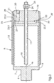
- FIG. 2 shows in longitudinal section one of a spray layer to be applied thermally the basic body.
- the shaping base body shown in longitudinal section comprises a Support cylinder 5, on the end face 7 of which the cylinder journal 6 is located.
- the Support cylinder 5 has a cavity, the end faces and Shell surfaces 8 limited and penetrated by a guide rod 17.
- To one annular end face 27 of the support cylinder 5 is a corresponding annular end face 28 of a pull-off disc 19.
- the Pull-off disc 19, also penetrated by the guide rod 17 already mentioned, which is provided with a profile 18 is with a connection 20 for a Media equipped.
- the connection 20 for the pressure medium comprises one Channel 21, which is in an expansion chamber 22 between the support cylinder 5 and the Pull-off disc 19 opens.
- the expansion chamber 22 is shown in FIG Idle state 22.1 shown.
- the through the mentioned end faces 27, 28 of Support cylinder 5 or pull-off disc 19 formed joint 29 forms an annular gap extending around the cylinder axis into a deflection chamfer 23 at the transition of the support cylinder 5 to the extraction disc 19 opens.
- Deflection chamfer 23.1 is provided as well as a deflection chamfer 23.2 on the condenser side is provided, which in the abutting state of the support cylinder 5 and Pulling disc 19 form a continuous deflection chamfer 23, which leads to the formation of a Constriction 30 leads in the thermal spray layer 14.
- the surface of the support cylinder 5 is conditioned by means of a blasting process.
- blasting processes are used to roughen subsurface surfaces with the aim of optimal adhesion. This means making the surface as sharp as possible.
- the spray layer 14 in order to ensure that the spray layer 14 can be easily removed, the roughness must be brought about with edges that are as round as possible.
- the surface of the support cylinder 5 is therefore produced using a blasting method using glass balls of a defined size and a blasting pressure between 2.5 and 3.5 bar.
- the average roughness depth R Z which is generated by this method, is R Z 25 ⁇ m.
- the jacket surface 8 conditioned in this way is provided with a release agent provided what is applied in a film up to 5 ⁇ m thick.
- a release agent such as graphite, silicone or Teflon, acts one mechanical clawing of the striking at high speed Spray particles against the base of the base body and prevents Baking together with the outer surface 8 of the support cylinder 5.
- the applied Release agent supports the detachment of the spray layer 14 after it has cooled the outer surface 8 of the base body.
- FIG. 3 shows a spray layer applied to the shaping base body shown with trained constriction 30.
- the expansion chamber 22 located between the support cylinder 5 and the pull-off disc 19 is in its idle state 22.1, ie not acted upon by a pressure medium.
- a constriction point 30 has formed in the spray layer 14.
- the outer surface of the removal disc 19 was not subjected to any surface conditioning, which is why its roughness is higher than that of the outer surface 8 of the support cylinder 5. This means that the part of the spray layer 14 which is applied to the pull-off disc 19 of the shaping base body opposes the detachment with a higher resistance.
- the expansion chamber 22, which is still in the idle state 22.1, is connected to the latter via the gap 29 defined by the contact area of the end face 27 or 28 of the support cylinder 5 or pull-off probe 19, which opens approximately centrally into the deflection chamfer 23.
- FIG. 4 shows a part that has been detached due to the expansion chamber being acted upon coherent thermal spray coating.
- the pull-off disc 19 is acted upon by a pressure medium, which via the Channel 21 acts on the expansion chamber 22.
- a pressure medium which via the Channel 21 acts on the expansion chamber 22.
- By building up Pressure in the expansion chamber 22 results in a surface pressure between the Support cylinder 5 and the pull-off disc 19, whereby the gap 29 between the End faces 27, 28 of the support cylinder 5 and pull-off 19 is widened.
- the gap 29 passes the pressure medium under the coherent sleeve-shaped Spray layer 14 and applied to the underside 14.2.
- the Deflection phase 23 In order to avoid a sudden impact on the spray layer 14 beginning formation of the gap 29 by the pressure medium is carried out by the Deflection phase 23 generates an additional length in the form of a constriction 30.
- the area covering the support cylinder 5 is the spray layer 14 detached from the outer surface 8 of the support cylinder 5 while the part of the spray layer 14, which is located on the peel 19, because of the greater friction still adheres to the outer surface of the extraction disc 19.
- Sleeves produced in this way without a seam have a ductile elastic Behavior on and are in the manner described above according to the invention can be produced considerably more cost-effectively than those known from the prior art elaborately deposited on a master cylinder Nickel sleeves.
- the material thicknesses of the tubular bodies to be produced are adjustable between 0.1 and 0.6mm depending on feed and speed of the shaping basic body, in relation to the material discharge on Spray head 11.
- Metal or sprayed metal alloys can be used, for example, for that Apply the necessary transfer layers using offset processes or pressers for Manufacture gravure applications. It is also used as a sleeve Printing form in printing machines possible to use instead of finite Printing plates.
Landscapes
- Chemical & Material Sciences (AREA)
- Engineering & Computer Science (AREA)
- Mechanical Engineering (AREA)
- Plasma & Fusion (AREA)
- Chemical Kinetics & Catalysis (AREA)
- Materials Engineering (AREA)
- Physics & Mathematics (AREA)
- Metallurgy (AREA)
- Organic Chemistry (AREA)
- Coating By Spraying Or Casting (AREA)
- Manufacture Or Reproduction Of Printing Formes (AREA)
- Printing Plates And Materials Therefor (AREA)
- Application Of Or Painting With Fluid Materials (AREA)
Applications Claiming Priority (2)
| Application Number | Priority Date | Filing Date | Title |
|---|---|---|---|
| DE19740245 | 1997-09-12 | ||
| DE19740245A DE19740245A1 (de) | 1997-09-12 | 1997-09-12 | Thermisches Spritzverfahren für Trägerkörper und Vorrichtung zur Durchführung des Verfahrens |
Publications (2)
| Publication Number | Publication Date |
|---|---|
| EP0902100A1 true EP0902100A1 (fr) | 1999-03-17 |
| EP0902100B1 EP0902100B1 (fr) | 2003-03-12 |
Family
ID=7842216
Family Applications (1)
| Application Number | Title | Priority Date | Filing Date |
|---|---|---|---|
| EP98111596A Expired - Lifetime EP0902100B1 (fr) | 1997-09-12 | 1998-06-24 | Procédé et appareil de pulvérisation thermique pour corps de support |
Country Status (3)
| Country | Link |
|---|---|
| EP (1) | EP0902100B1 (fr) |
| JP (1) | JPH11165478A (fr) |
| DE (2) | DE19740245A1 (fr) |
Cited By (1)
| Publication number | Priority date | Publication date | Assignee | Title |
|---|---|---|---|---|
| AU2006326928B2 (en) * | 2005-12-23 | 2012-04-19 | Commonwealth Scientific And Industrial Research Organisation | Manufacture of printing cylinders |
Families Citing this family (3)
| Publication number | Priority date | Publication date | Assignee | Title |
|---|---|---|---|---|
| DE102005031164A1 (de) * | 2005-07-04 | 2007-01-18 | Koenig & Bauer Ag | Oberfläche für bedruckstoffführende Teile einer Druckmaschine und Verfahren zur Herstellung einer solchen Oberfläche |
| DE102009007678B4 (de) * | 2009-02-03 | 2010-12-16 | Sächsische Walzengravur GmbH | Hülse als Tiefdruckform |
| GB202218048D0 (en) | 2022-12-01 | 2023-01-18 | Rolls Royce Plc | Freestanding ceramic tile manufacture |
Citations (7)
| Publication number | Priority date | Publication date | Assignee | Title |
|---|---|---|---|---|
| US3112539A (en) * | 1960-11-17 | 1963-12-03 | Gen Motors Corp | Forming articles by arc plasma spraying |
| GB1215184A (en) * | 1968-07-02 | 1970-12-09 | Chelton Forming Ltd | Improvements in or relating to the making of hollow articles by metal spraying |
| GB1410169A (en) * | 1971-06-17 | 1975-10-15 | Johnson Matthey Co Ltd | Method of making composite layered structures by spraying |
| FR2472033A1 (fr) * | 1979-12-21 | 1981-06-26 | Castolin Sa | Fabrication de corps creux, par projection thermique, par exemple par chalumeau ou torche a plasma, d'alliages metalliques et/ou de matieres ceramiques |
| JPS57198256A (en) * | 1981-05-27 | 1982-12-04 | Isuzu Motors Ltd | Production of thin-walled cylindrical body having smooth inside circumferential surface and abrasion resistance |
| DE3617833C1 (de) * | 1986-05-27 | 1987-09-03 | Mannesmann Ag | Verfahren zum Herstellen von rotationssymmetrischen Hohlkoerpern |
| EP0305142A1 (fr) * | 1987-08-28 | 1989-03-01 | Corning Glass Works | Procédé pour façonner une pièce à la géométrie désirée |
Family Cites Families (10)
| Publication number | Priority date | Publication date | Assignee | Title |
|---|---|---|---|---|
| GB1599392A (en) * | 1978-05-31 | 1981-09-30 | Osprey Metals Ltd | Method and apparatus for producing workable spray deposits |
| DE3046757C2 (de) * | 1980-12-12 | 1985-09-12 | W.C. Heraeus Gmbh, 6450 Hanau | Tiefdruckzylinder |
| DE3447557C2 (de) * | 1984-12-21 | 1987-05-14 | Mannesmann AG, 4000 Düsseldorf | Vorrichtung zur Herstellung eines Hohlzylinders durch Zerstäuben einer Metallschmelze mittels Gaszerstäubung, sowie ein solcher Hohlzylinder |
| US4903597A (en) * | 1988-10-24 | 1990-02-27 | Lavalley Industries, Inc. | Printing sleeves and methods for mounting and dismounting |
| DE9007784U1 (de) * | 1989-03-18 | 1996-01-18 | MAN Roland Druckmaschinen AG, 63075 Offenbach | Druckmaschine |
| DE3942702C1 (en) * | 1989-12-20 | 1990-12-20 | Mannesmann Ag, 4000 Duesseldorf, De | Spray compacting of tube blooms or tubes - using torch which atomises liq. metal stream using vertical force to increase rigidity |
| CA2038273A1 (fr) * | 1990-06-29 | 1991-12-30 | Paul A. Siemers | Procede de fabrication de tubes au moyen d'un mandrin reutilisable |
| DE4208023C2 (de) * | 1991-06-10 | 1994-04-07 | Banning Gmbh J | Verfahren und Vorrichtung zur Herstellung rotationssymmetrischer Teile aus Metall |
| DE4130264A1 (de) * | 1991-09-12 | 1993-03-18 | Roland Man Druckmasch | Formzylinder in einer offsetdruckmaschine |
| DE4315813A1 (de) * | 1993-05-12 | 1994-11-17 | Hoechst Ag | Verfahren zur Herstellung von Druckwalzen aus einem metallischen Kernzylinder und einer Kupfer- oder Kupferlegierungsauflage |
-
1997
- 1997-09-12 DE DE19740245A patent/DE19740245A1/de not_active Withdrawn
-
1998
- 1998-06-24 DE DE59807441T patent/DE59807441D1/de not_active Expired - Fee Related
- 1998-06-24 EP EP98111596A patent/EP0902100B1/fr not_active Expired - Lifetime
- 1998-09-11 JP JP10258424A patent/JPH11165478A/ja active Pending
Patent Citations (7)
| Publication number | Priority date | Publication date | Assignee | Title |
|---|---|---|---|---|
| US3112539A (en) * | 1960-11-17 | 1963-12-03 | Gen Motors Corp | Forming articles by arc plasma spraying |
| GB1215184A (en) * | 1968-07-02 | 1970-12-09 | Chelton Forming Ltd | Improvements in or relating to the making of hollow articles by metal spraying |
| GB1410169A (en) * | 1971-06-17 | 1975-10-15 | Johnson Matthey Co Ltd | Method of making composite layered structures by spraying |
| FR2472033A1 (fr) * | 1979-12-21 | 1981-06-26 | Castolin Sa | Fabrication de corps creux, par projection thermique, par exemple par chalumeau ou torche a plasma, d'alliages metalliques et/ou de matieres ceramiques |
| JPS57198256A (en) * | 1981-05-27 | 1982-12-04 | Isuzu Motors Ltd | Production of thin-walled cylindrical body having smooth inside circumferential surface and abrasion resistance |
| DE3617833C1 (de) * | 1986-05-27 | 1987-09-03 | Mannesmann Ag | Verfahren zum Herstellen von rotationssymmetrischen Hohlkoerpern |
| EP0305142A1 (fr) * | 1987-08-28 | 1989-03-01 | Corning Glass Works | Procédé pour façonner une pièce à la géométrie désirée |
Non-Patent Citations (1)
| Title |
|---|
| PATENT ABSTRACTS OF JAPAN vol. 007, no. 046 (C - 153) 23 February 1983 (1983-02-23) * |
Cited By (1)
| Publication number | Priority date | Publication date | Assignee | Title |
|---|---|---|---|---|
| AU2006326928B2 (en) * | 2005-12-23 | 2012-04-19 | Commonwealth Scientific And Industrial Research Organisation | Manufacture of printing cylinders |
Also Published As
| Publication number | Publication date |
|---|---|
| DE19740245A1 (de) | 1999-03-18 |
| EP0902100B1 (fr) | 2003-03-12 |
| DE59807441D1 (de) | 2003-04-17 |
| JPH11165478A (ja) | 1999-06-22 |
Similar Documents
| Publication | Publication Date | Title |
|---|---|---|
| DE68905420T2 (de) | Verfahren zum verbinden eines werkzeugmaterials mit einem traeger und danach hergestelltes werkzeug. | |
| DE69708303T2 (de) | Linear-reibschweissverfahren zum herstellen von radfelgen | |
| EP0655561B1 (fr) | Rouleau en matière plastique renforcée de fibres à surface rainurée en losanges | |
| DD202635A5 (de) | Vorrichtung und verfahren zum kontinuierlichen, durch reibung ausgeloesten strangpressen | |
| EP0902100B1 (fr) | Procédé et appareil de pulvérisation thermique pour corps de support | |
| DE19549403A1 (de) | Verfahren zum Herstellen einer Gleitfläche auf einer Aluminiumlegierung | |
| EP1316423B1 (fr) | Rouleau tramé et méthode pour sa production et retraitement | |
| EP2024654A2 (fr) | Composant de palier à roulement et procédé de fabrication dudit composant | |
| EP1144200B1 (fr) | Manchon en materiau thermoformable et procede permettant de le produire | |
| DE19918432A1 (de) | Dehnschicht aus kompressiblem Material | |
| DE19820498C2 (de) | Verfahren zum Herstellen einer Hülse, insbesondere für die Druckindustrie | |
| WO2018206367A1 (fr) | Procédé servant à fabriquer un bloc-moteur | |
| EP1543962B1 (fr) | Cylindre d'héliogravure | |
| EP2045092B1 (fr) | Manchon en caoutchouc | |
| DE2253874C3 (de) | Verwendung eines hohlzylindrischen Stützgliedes als Formkern | |
| DE19959199A1 (de) | Gleitlager mit einer Kunststofffolie als Lauffläche und Verfahren zu seiner Herstellung | |
| EP1967360A2 (fr) | Manchon et outil de serrage destinés à l'utilisation dans un système constitué d'un outil de serrage et d'au moins un manchon | |
| DE10236929A1 (de) | Beschichtungsverfahren für eine Rolle oder einen Zylinder | |
| WO2007071542A1 (fr) | Revetement pour coquille destinee a une installation de coulee continue, et procede de revetement correspondant | |
| EP0795387B1 (fr) | Dispositif de moulage par injection de matières plastiques | |
| DE102023004280A1 (de) | Batteriezelle für eine Batterie, Verfahren zur Herstellung einer solchen Batteriezelle sowie Fahrzeug mit einer Batterie | |
| DE2411448C2 (de) | Metallisches Gießband für Stranggießkokillen | |
| DE102023119603A1 (de) | Verfahren zum Herstellen einer Bremsscheibe, Bremsscheibe sowie Kraftfahrzeug | |
| EP3544807B1 (fr) | Élément adaptateur, procédé de fabrication d'un élément adaptateur, et système d'assemblage muni d'un élément adaptateur | |
| DE3527864A1 (de) | Verfahren zum strangpressen bzw. strangziehen |
Legal Events
| Date | Code | Title | Description |
|---|---|---|---|
| PUAI | Public reference made under article 153(3) epc to a published international application that has entered the european phase |
Free format text: ORIGINAL CODE: 0009012 |
|
| 17P | Request for examination filed |
Effective date: 19980624 |
|
| AK | Designated contracting states |
Kind code of ref document: A1 Designated state(s): CH DE FR GB IT LI |
|
| AX | Request for extension of the european patent |
Free format text: AL;LT;LV;MK;RO;SI |
|
| AKX | Designation fees paid |
Free format text: CH DE FR GB IT LI |
|
| 17Q | First examination report despatched |
Effective date: 20010302 |
|
| GRAH | Despatch of communication of intention to grant a patent |
Free format text: ORIGINAL CODE: EPIDOS IGRA |
|
| GRAH | Despatch of communication of intention to grant a patent |
Free format text: ORIGINAL CODE: EPIDOS IGRA |
|
| GRAA | (expected) grant |
Free format text: ORIGINAL CODE: 0009210 |
|
| AK | Designated contracting states |
Designated state(s): CH DE FR GB IT LI |
|
| PG25 | Lapsed in a contracting state [announced via postgrant information from national office to epo] |
Ref country code: GB Free format text: LAPSE BECAUSE OF FAILURE TO SUBMIT A TRANSLATION OF THE DESCRIPTION OR TO PAY THE FEE WITHIN THE PRESCRIBED TIME-LIMIT Effective date: 20030312 Ref country code: FR Free format text: LAPSE BECAUSE OF FAILURE TO SUBMIT A TRANSLATION OF THE DESCRIPTION OR TO PAY THE FEE WITHIN THE PRESCRIBED TIME-LIMIT Effective date: 20030312 |
|
| REG | Reference to a national code |
Ref country code: GB Ref legal event code: FG4D Free format text: NOT ENGLISH |
|
| REG | Reference to a national code |
Ref country code: CH Ref legal event code: EP |
|
| REF | Corresponds to: |
Ref document number: 59807441 Country of ref document: DE Date of ref document: 20030417 Kind code of ref document: P |
|
| GBV | Gb: ep patent (uk) treated as always having been void in accordance with gb section 77(7)/1977 [no translation filed] |
Effective date: 20030312 |
|
| PLBE | No opposition filed within time limit |
Free format text: ORIGINAL CODE: 0009261 |
|
| STAA | Information on the status of an ep patent application or granted ep patent |
Free format text: STATUS: NO OPPOSITION FILED WITHIN TIME LIMIT |
|
| EN | Fr: translation not filed | ||
| 26N | No opposition filed |
Effective date: 20031215 |
|
| PGFP | Annual fee paid to national office [announced via postgrant information from national office to epo] |
Ref country code: CH Payment date: 20070626 Year of fee payment: 10 |
|
| PGFP | Annual fee paid to national office [announced via postgrant information from national office to epo] |
Ref country code: DE Payment date: 20070630 Year of fee payment: 10 |
|
| PGFP | Annual fee paid to national office [announced via postgrant information from national office to epo] |
Ref country code: IT Payment date: 20070627 Year of fee payment: 10 |
|
| REG | Reference to a national code |
Ref country code: CH Ref legal event code: PL |
|
| PG25 | Lapsed in a contracting state [announced via postgrant information from national office to epo] |
Ref country code: DE Free format text: LAPSE BECAUSE OF NON-PAYMENT OF DUE FEES Effective date: 20090101 |
|
| PG25 | Lapsed in a contracting state [announced via postgrant information from national office to epo] |
Ref country code: LI Free format text: LAPSE BECAUSE OF NON-PAYMENT OF DUE FEES Effective date: 20080630 Ref country code: CH Free format text: LAPSE BECAUSE OF NON-PAYMENT OF DUE FEES Effective date: 20080630 |
|
| PG25 | Lapsed in a contracting state [announced via postgrant information from national office to epo] |
Ref country code: IT Free format text: LAPSE BECAUSE OF NON-PAYMENT OF DUE FEES Effective date: 20080624 |