EP0902110A2 - Method for connecting two knitted parts on a flat bed knitting machine - Google Patents
Method for connecting two knitted parts on a flat bed knitting machine Download PDFInfo
- Publication number
- EP0902110A2 EP0902110A2 EP98115237A EP98115237A EP0902110A2 EP 0902110 A2 EP0902110 A2 EP 0902110A2 EP 98115237 A EP98115237 A EP 98115237A EP 98115237 A EP98115237 A EP 98115237A EP 0902110 A2 EP0902110 A2 EP 0902110A2
- Authority
- EP
- European Patent Office
- Prior art keywords
- knitted
- needle
- parts
- stitches
- knitted parts
- Prior art date
- Legal status (The legal status is an assumption and is not a legal conclusion. Google has not performed a legal analysis and makes no representation as to the accuracy of the status listed.)
- Granted
Links
Images


Classifications
-
- D—TEXTILES; PAPER
- D04—BRAIDING; LACE-MAKING; KNITTING; TRIMMINGS; NON-WOVEN FABRICS
- D04B—KNITTING
- D04B1/00—Weft knitting processes for the production of fabrics or articles not dependent on the use of particular machines; Fabrics or articles defined by such processes
- D04B1/22—Weft knitting processes for the production of fabrics or articles not dependent on the use of particular machines; Fabrics or articles defined by such processes specially adapted for knitting goods of particular configuration
Definitions
- the present invention proposes a method of joining two knitted parts on a flat knitting machine with at least two opposite needle beds, a needle bed offset device and a mesh wrap, which is characterized in that the two knitted parts hung in adjacent needles of a needle bed and then the stitches of a knitted part by so many needle gaps be hung in the direction of the other knitted part, that the two respective border stitches on a needle come and be knitted together before a reassigning the stitches of one of the knitted parts by so much Needle gaps that the border stitches are on top of each other, and knitting the border stitches, and this process is repeated until all the stitches of the two knitted parts are interconnected.
- the knitted parts can preferably alternating in the direction of the other piece of knitted fabric be reassigned.
- connection seam between knitted parts via a needle what corresponds to the finest possible connection.
- methods can also be used for connecting seams over several Make knitting needles if this is due to the pattern or desired to achieve a special connection effect becomes.
- Fig. 1 shows a sweater 10, the collar 11 of two knitted parts 11a and 11b is composed, the two Parts 11a, 11b at the connection point 12 in the area of Neck still attached to each other on the knitting machine become.
- the knitted fabric 20 shown in FIG. 2 shows one Vest, the front parts 21 and 22 with the back part 23 in Area of the shoulders 24 according to a method according to the invention get connected.
- the knitted fabrics 10 and 20 of FIGS. 1 and 2 are knitted fabrics, the knitted parts 11a, 11b and 21, 22 and 23 are formed in the same knitting plane.
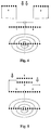
- Fig. 3 shows a knitted fabric 30 with a collar 31, which consists of two Parts 31a and 31b are assembled on opposite sides Needle beds are made and then on one Connection point 32 are connected to each other in the neck.
- FIG. 4 The connection of the knitted parts 11a, 11b or 21, 22 and 23 the knitted fabrics 10 and 20 from FIGS. 1 and 2 is in FIG. 4 shown schematically.
- the two knitted pieces which are designated here with 1 and 2 and on the same Hang the needle bed in neighboring needles of this needle bed hanged.
- the generation of superimposed Border stitches knitted one after the other become.
- Fig. 5 is the method of connecting the two Collar parts 31a and 31b of the knitted fabric 30 from FIG.
- the two pieces of knitted fabric which are labeled 1 and 2 here are on opposite needle beds. Before joining, they are put on a needle bed, and in such a way that they are in adjacent needles of this needle bed hang. Then the actual connection is made Reassigning the stitches of a knitted part towards the other knitted part and knitting the one above the other Border stitches as in Fig. 4.
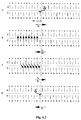
- Fig. 6 shows an illustration of a course of the mesh actual connection of the two knitted parts 1 and 2 4 and 5, after this one on adjacent needles Needle bed, here the front needle bed V, has been reassigned are. However, the connection could also be on the needles of the rear needle bed.
- the boundary line between the two knitted parts 1 and 2 is designated by 40. After the connecting previous necking operations of the two Knitted parts 1 and 2 result in the one shown in row 1 Image. Then row 2 over the right knitted part Stitches formed so that the associated thread guide to the left of the needle L of the left knitted part can. The connection is subsequently made with the needle L. educated.
- Row 3 will be in the knitting direction from the left to the right with a first S1 knitting system the right part of the knitted fabric on the rear needle bed H.
- Row 4 is done in the knitting direction from right to left after an offset movement of the rear needle bed H after on the left is the hanging back of the stitches of the right knitted part from the rear needle bed H to the front needle bed V. All Stitches in the right part of the knitted fabric are thus one needle in Direction towards the left knitted part. As a result, the border stitch of the left one lies on the needle L. Knitted part and the border stitch of the right knitted part.
- Row 5 is in the knitting direction from left to right the first knitting system S1 and the thread guide knitted double stitch and thus the two knitted parts connected.
Landscapes
- Engineering & Computer Science (AREA)
- Textile Engineering (AREA)
- Knitting Machines (AREA)
- Knitting Of Fabric (AREA)
Abstract
Description
Die Fertigung von Gestrickstücken, die aus mehreren einzelnen Gestrickteilen zusammengesetzt sind, fordert in der Regel Nachbearbeitungsschritte, die meistens nicht zu automatisieren und deswegen sehr kostenintensiv sind. Für eine rationelle Fertigung von Gestrickstücken ist daher die Entwicklung von Verfahren zum maschinellen Verbinden von Gestrickteilen während des Strickprozesses erforderlich, wobei die entstehenden Verbindungsstellen alle Anforderungen hinsichtlich optischem Eindruck und Tragekomfort erfüllen müssen.The manufacture of knitted pieces that consist of several individual Knitted parts are usually assembled Post-processing steps, most of which cannot be automated and are therefore very expensive. For a rational Manufacture of knitted pieces is therefore the development of Process for mechanically joining knitted parts during of the knitting process, the resulting Connection points all requirements regarding optical Must have impression and comfort.
Die vorliegende Erfindung schlägt ein Verfahren zum Verbinden zweier Gestrickteile auf einer Flachstrickmaschine mit mindestens zwei gegenüberliegenden Nadelbetten, einer Nadelbetten-Versatzeinrichtung und einer Maschenumhängeeinrichtung vor, das dadurch gekennzeichnet ist, daß die beiden Gestrickteile in benachbarte Nadeln eines Nadelbettes gehängt und anschließend die Maschen eines Gestrickteiles um soviele Nadelabstände in Richtung auf das andere Gestrickteil weitergehängt werden, daß die beiden jeweiligen Grenzmaschen auf einer Nadel zu liegen kommen und gemeinsam abgestrickt werden, bevor ein erneutes Umhängen der Maschen eines der Gestrickteile um soviele Nadelabstände, daß die Grenzmaschen übereinanderliegen, und ein Abstricken der Grenzmaschen erfolgt, und dieser Vorgang wiederholt wird, bis alle Maschen der beiden Gestrickteile miteinander verbunden sind. Die Gestrickteile können dabei vorzugsweise im Wechsel in Richtung auf das andere Gestrickstück umgehängt werden. Dieses Verfahren kann für Gestrickteile in allen Bindungs- und Musterarten angewendet werden. Da die Verbindungsnaht flach sein soll und nicht aus den verbundenen Gestrickteilen hervorstehen darf, ist die Verbindungsstrickreihe einflächig. Beim Verbinden mehrflächiger Gestrickteile können diese vor dem Nebeneinanderhängen auf ein Nadelbett mit einer einflächigen Abschlußreihe versehen werden. Bei Gestrickteilen, die sektoral abwechselnd auf einem der beiden Nadelbetten erzeugt werden, können die Maschen nach der letzten Strickreihe so umgehängt werden, daß sich alle Maschen auf einem Nadelbett befinden. Mit dem erfindungsgemäßen Verfahren lassen sich Verbindungsnähte herstellen, die vertikal, horizontal oder in einem beliebigen anderen Winkel verlaufen.The present invention proposes a method of joining two knitted parts on a flat knitting machine with at least two opposite needle beds, a needle bed offset device and a mesh wrap, which is characterized in that the two knitted parts hung in adjacent needles of a needle bed and then the stitches of a knitted part by so many needle gaps be hung in the direction of the other knitted part, that the two respective border stitches on a needle come and be knitted together before a reassigning the stitches of one of the knitted parts by so much Needle gaps that the border stitches are on top of each other, and knitting the border stitches, and this process is repeated until all the stitches of the two knitted parts are interconnected. The knitted parts can preferably alternating in the direction of the other piece of knitted fabric be reassigned. This procedure can be used for knitted parts applied in all weave and pattern types become. Since the seam should be flat and not made the knitted parts may protrude, is the Single row of connecting cables. When connecting multiple surfaces Knitted parts can hang these up before hanging them side by side provide a needle bed with a single-row end row become. In the case of knitted parts which alternate on one sector of the two needle beds, the stitches can be of the last row of knitting so that everyone Stitches are on a needle bed. With the invention Processes can be used to produce seams that vertical, horizontal or at any other angle run.
Die nachfolgend anhand der Zeichnung näher erläuterten Ausführungsbeispiele des erfindungsgemäßen Verfahrens bilden eine Verbindungsnaht zwischen Gestrickteilen über eine Nadel, was der feinstmöglichen Verbindung entspricht. Nach demselben Verfahren lassen sich aber auch Verbindungsnähte über mehrere Stricknadeln herstellen, falls dies aufgrund des Musters oder zur Erzielung eines besonderen Verbindungseffekts gewünscht wird.The exemplary embodiments explained in more detail below with reference to the drawing of the method according to the invention form a Connection seam between knitted parts via a needle what corresponds to the finest possible connection. After the same However, methods can also be used for connecting seams over several Make knitting needles if this is due to the pattern or desired to achieve a special connection effect becomes.
Es zeigen:
- Fig. 1
- eine Ansicht eines ersten, aus zwei Teilgestricken gebildeten Gestrickes mit vertikalem Verlauf der Verbindungsnaht;
- Fig. 2
- eine Ansicht eines zweiten, aus drei Teilgestricken gebildeten Gestrickes mit horizontalem Verlauf der Verbindungsnaht;
- Fig. 3
- eine Ansicht eines dritten, aus zwei Teilgestricken gebildeten Gestrickes mit vertikalem Verlauf der Verbindungsnaht;
- Fig. 4
- eine schematische Darstellung der Verbindung der Gestrickteile der Gestricke aus Fig. 1 und Fig. 2;
- Fig. 5
- eine schematische Darstellung der Verbindung der beiden Gestrickteile des Gestrickes aus Fig. 3;
- Fig. 6
- eine Darstellung eines Maschenverlaufes der Verbindung zweier Gestrickteile.
- Fig. 1
- a view of a first knitted fabric formed from two partial knitted fabrics with a vertical course of the connecting seam;
- Fig. 2
- a view of a second, formed from three partial knits with a horizontal course of the connecting seam;
- Fig. 3
- a view of a third knitted fabric formed from two partial knitted fabrics with a vertical course of the connecting seam;
- Fig. 4
- a schematic representation of the connection of the knitted parts of the knitted fabrics of Fig. 1 and Fig. 2;
- Fig. 5
- a schematic representation of the connection of the two knitted parts of the knitted fabric from FIG. 3;
- Fig. 6
- a representation of a stitch course of the connection of two knitted parts.
Fig. 1 zeigt einen Pullover 10, dessen Kragen 11 aus zwei Gestrickteilen
11a und 11b zusammengesetzt ist, wobei die beiden
Teile 11a, 11b an der Verbindungsstelle 12 im Bereich des
Nackens noch auf der Strickmaschine miteinander verbunden
werden. Das in Fig. 2 dargestellte Gestrick 20 zeigt eine
Weste, dessen Vorderteile 21 und 22 mit dem Rückenteil 23 im
Bereich der Schultern 24 nach einem erfindungsgemäßen Verfahren
verbunden werden. Die Gestricke 10 und 20 der Fig. 1 und
2 sind Gestricke, deren Gestrickteile 11a, 11b bzw. 21, 22 und
23 in derselben Strickebene gebildet werden. Demgegenüber
zeigt Fig. 3 ein Gestrick 30 mit einem Kragen 31, der aus zwei
Teilen 31a und 31b zusammengesetzt ist, die auf gegenüberliegenden
Nadelbetten gefertigt werden und anschließend an einer
Verbindungsstelle 32 im Nacken miteinander verbunden werden. Fig. 1 shows a
Die Verbindung der Gestrickteile 11a, 11b bzw. 21, 22 und 23
der Gestricke 10 und 20 aus den Fig. 1 und 2 ist in Fig. 4
schematisch dargestellt. Zunächst werden die beiden Gestrickteile,
die hier mit 1 und 2 bezeichnet sind und auf dem gleichen
Nadelbett hängen, in benachbarte Nadeln dieses Nadelbettes
gehängt. Anschließend erfolgt durch wechselseitiges Umhängen
der Maschen der Gestrickteile 1 und 2 in Richtung auf das
jeweils andere Gestrickteil 2, 1 die Erzeugung von übereinanderliegenden
Grenzmaschen, die nacheinander abgestrickt
werden. Hierdurch entsteht eine maschengenaue Verbindung der
beiden Gestrickteile 1 und 2, die außerdem nicht aufträgt,
also den Tragekomfort eines Kleidungsstückes nicht einschränkt.
In Fig. 5 ist das Verfahren zur Verbindung der beiden
Kragenteile 31a und 31b des Gestrickes 30 aus Fig. 3 skizziert.
Die beiden Gestrickteile, die hier mit 1 und 2 bezeichnet
sind, befinden sich auf gegenüberliegenden Nadelbetten.
Vor dem Verbinden werden sie auf ein Nadelbett umgehängt, und
zwar derart, daß sie in benachbarten Nadeln dieses Nadelbettes
hängen. Anschließend erfolgt die eigentliche Verbindung durch
Umhängen der Maschen eines Gestrickteiles in Richtung auf das
andere Gestrickteil und Abstricken der übereinanderliegenden
Grenzmaschen, wie in Fig. 4.The connection of the knitted
Fig. 6 zeigt eine Darstellung eines Maschenverlaufes der
eigentlichen Verbindung der beiden Gestrickteile 1 und 2 aus
den Fig. 4 und 5, nach dem diese auf benachbarte Nadeln eines
Nadelbettes, hier dem vorderen Nadelbett V, umgehängt worden
sind. Die Verbindung könnte jedoch ebenso auf den Nadeln des
hinteren Nadelbettes erfolgen. Die Grenzlinie zwischen den
beiden Gestrickteilen 1 und 2 ist mit 40 bezeichnet. Nach den
dem Verbinden vorangehenden Umhängevorgängen der beiden
Gestrickteile 1 und 2 ergibt sich das in Reihe 1 gezeigte
Bild. Anschließend werden in Reihe 2 über dem rechten Gestrickteil
Maschen gebildet, damit der zugehörige Fadenführer
links von der Nadel L des linken Gestrickteiles plaziert werden
kann. Mit der Nadel L wird nachfolgend die Verbindung
gebildet. In Reihe 3 werden dann in Strickrichtung von links
nach rechts mit einem ersten Stricksystem S1 die Maschen des
rechten Gestrickteiles auf das hintere Nadelbett H umgehängt.
In Reihe 4 erfolgt in Strickrichtung von rechts nach links
nach einer Versatzbewegung des hinteren Nadelbettes H nach
links das Zurückhängen der Maschen des rechten Gestrickteiles
vom hinteren Nadelbett H auf das vordere Nadelbett V. Alle
Maschen des rechten Gestrickteiles sind damit um eine Nadel in
Richtung auf das linke Gestrickteil hin versetzt worden.
Hierdurch liegen auf der Nadel L die Grenzmasche des linken
Gestrickteiles und die Grenzmasche des rechten Gestrickteiles.
In Reihe 5 wird in Strickrichtung von links nach rechts mit
dem ersten Stricksystem S1 und dem Fadenführer die sich auf
der Nadel L befindende Doppelmasche abgestrickt und damit die
beiden Gestrickteile verbunden. Anschließend befindet sich der
Fadenführer rechts von der Nadel L. In Reihe 6 werden dann
sämtliche Maschen des linken Gestrickteiles vom vorderen
Nadelbett V auf das hintere Nadelbett H umgehängt. In Reihe 7
erfolgt nach einer Versatzbewegung des hinteren Nadelbettes H
nach rechts mit dem ersten Stricksystem S1 das Zurückhängen
der Maschen des linken Gestrickteiles vom hinteren Nadelbett H
auf das vordere Nadelbett V. Alle Maschen des linken Gestrickteiles
sind nun um eine Nadel nach rechts versetzt worden.
Dadurch liegen nun auf der Nadel L die Verbindungsmasche aus
Reihe 5 und die Grenzmasche des linken Gestrickstückes. Diese
Doppelmasche wird in Reihe 8 in Strickrichtung von rechts nach
links mit dem ersten Stricksystem S1 und dem Fadenführer
abgestrickt und somit abgebunden. Der Fadenführer steht nun
wieder links neben der Nadel L. Anschließend wird der Zyklus
der Reihen 3 bis 8 solange wiederholt, bis alle Maschen der
Gestrickteile im Bereich der Verbindungsstelle miteinander
verbunden sind.Fig. 6 shows an illustration of a course of the mesh
actual connection of the two knitted
Claims (6)
Applications Claiming Priority (2)
| Application Number | Priority Date | Filing Date | Title |
|---|---|---|---|
| DE19739136 | 1997-09-06 | ||
| DE19739136A DE19739136A1 (en) | 1997-09-06 | 1997-09-06 | Method for connecting two knitted parts on a flat knitting machine |
Publications (3)
| Publication Number | Publication Date |
|---|---|
| EP0902110A2 true EP0902110A2 (en) | 1999-03-17 |
| EP0902110A3 EP0902110A3 (en) | 2000-04-12 |
| EP0902110B1 EP0902110B1 (en) | 2004-03-24 |
Family
ID=7841487
Family Applications (1)
| Application Number | Title | Priority Date | Filing Date |
|---|---|---|---|
| EP98115237A Expired - Lifetime EP0902110B1 (en) | 1997-09-06 | 1998-08-13 | Method for connecting two knitted parts on a flat bed knitting machine |
Country Status (4)
| Country | Link |
|---|---|
| US (1) | US6192716B1 (en) |
| EP (1) | EP0902110B1 (en) |
| DE (2) | DE19739136A1 (en) |
| ES (1) | ES2215257T3 (en) |
Cited By (1)
| Publication number | Priority date | Publication date | Assignee | Title |
|---|---|---|---|---|
| EP1375718A4 (en) * | 2001-03-02 | 2004-03-31 | Shima Seiki Mfg | KNITTING HAVING AN OPENING PORTION AND KNITTING METHOD THEREOF |
Families Citing this family (10)
| Publication number | Priority date | Publication date | Assignee | Title |
|---|---|---|---|---|
| JP3887409B2 (en) * | 2000-06-05 | 2007-02-28 | 株式会社島精機製作所 | Knitted fabric joining method and joined knitted fabric |
| US6918270B2 (en) * | 2001-12-28 | 2005-07-19 | Shima Seiki Mfg., Ltd. | Neck forming method |
| WO2003100146A1 (en) * | 2002-05-27 | 2003-12-04 | Shima Seiki Mfg., Ltd. | Method of knitting knit-wear |
| EP1584720B1 (en) * | 2004-04-08 | 2010-10-27 | H. Stoll GmbH & Co. KG | Method of linking two knit fabrics |
| DE102010012151B4 (en) * | 2010-03-20 | 2013-08-01 | H. Stoll Gmbh & Co. Kg | Process for the production of a tubular round finished knitted fabric |
| JP6104080B2 (en) * | 2013-07-10 | 2017-03-29 | 株式会社島精機製作所 | Method for knitting a tubular knitted fabric having a slit |
| CN108179535B (en) * | 2018-02-09 | 2020-06-23 | 福建睿能科技股份有限公司 | Computerized flat knitting machine, knitting method thereof and device with storage function |
| CN108179534B (en) * | 2018-02-09 | 2020-10-09 | 福建睿能科技股份有限公司 | Computerized flat knitting machine, knitting method thereof and device with storage function |
| US11825884B2 (en) | 2019-03-21 | 2023-11-28 | Nike, Inc. | Collar construction for an upper-body garment |
| CN114182421B (en) * | 2022-01-11 | 2023-02-28 | 嘉兴市蒂维时装有限公司 | Knitting method for improving skew of edge of fully-formed rib lower hem top fly and knitted fabric |
Family Cites Families (9)
| Publication number | Priority date | Publication date | Assignee | Title |
|---|---|---|---|---|
| DE4008057A1 (en) * | 1990-03-14 | 1991-09-19 | Stoll & Co H | KNITTED PATTERN |
| JPH0823102B2 (en) * | 1990-03-28 | 1996-03-06 | 株式会社島精機製作所 | Method of connecting knitting of band-shaped knitting ends and knitted fabric in which band-shaped knitting ends are connected |
| JPH0772384B2 (en) | 1990-06-05 | 1995-08-02 | 株式会社島精機製作所 | Knitted fabric joining method and knitted fabric with beautiful joint |
| JPH0772385B2 (en) * | 1990-06-21 | 1995-08-02 | 株式会社島精機製作所 | Knitting method of joined knitted fabrics |
| DE4130345C2 (en) * | 1991-09-12 | 2000-04-06 | Stoll & Co H | Method of manufacturing a garment on a flat knitting machine |
| DE4228408A1 (en) | 1992-08-26 | 1994-03-03 | Stoll & Co H | Process for the production of a form-fitting, one-piece flat knitted fabric for a piece of clothing with sleeves |
| JP2706760B2 (en) * | 1994-10-07 | 1998-01-28 | 株式会社島精機製作所 | How to organize |
| KR100392480B1 (en) * | 1995-04-10 | 2003-11-28 | 가부시키가이샤 시마세이키 세이사쿠쇼 | A method of binding off using a transverse knife and a method of binding- |
| IT1290915B1 (en) * | 1996-02-09 | 1998-12-14 | Shima Seiki Mfg | METHOD OF KNITTING ON A STRAIGHT LINE MACHINE FOR KNITTING AND KNITTED FABRIC SO PRODUCED. |
-
1997
- 1997-09-06 DE DE19739136A patent/DE19739136A1/en not_active Withdrawn
-
1998
- 1998-08-13 DE DE59811041T patent/DE59811041D1/en not_active Expired - Fee Related
- 1998-08-13 ES ES98115237T patent/ES2215257T3/en not_active Expired - Lifetime
- 1998-08-13 EP EP98115237A patent/EP0902110B1/en not_active Expired - Lifetime
- 1998-09-04 US US09/148,594 patent/US6192716B1/en not_active Expired - Fee Related
Cited By (1)
| Publication number | Priority date | Publication date | Assignee | Title |
|---|---|---|---|---|
| EP1375718A4 (en) * | 2001-03-02 | 2004-03-31 | Shima Seiki Mfg | KNITTING HAVING AN OPENING PORTION AND KNITTING METHOD THEREOF |
Also Published As
| Publication number | Publication date |
|---|---|
| EP0902110A3 (en) | 2000-04-12 |
| US6192716B1 (en) | 2001-02-27 |
| DE59811041D1 (en) | 2004-04-29 |
| EP0902110B1 (en) | 2004-03-24 |
| ES2215257T3 (en) | 2004-10-01 |
| DE19739136A1 (en) | 1999-03-11 |
Similar Documents
| Publication | Publication Date | Title |
|---|---|---|
| DE69712995T2 (en) | Process for knitting a knitted jacquard double jersey binding in a tubular knitted fabric | |
| DE69106068T2 (en) | Process for processing the end sections of a knitted fabric. | |
| DE69110296T2 (en) | TUBULAR KNIT WITH SLIT. | |
| DE69807546T2 (en) | Process for connecting cloth parts on a flat knitting machine | |
| DE69506072T2 (en) | Knitting process | |
| EP0584529B1 (en) | Method for manufacturing a fashioned integrally flat knit article for a sleeved garment | |
| EP0864681B1 (en) | Method for making knitwear on a flat bed knitting machine | |
| DE4006877B4 (en) | A method for joining tubular knitted sleeves with a tubular body part on a flat knitting machine | |
| DE69617617T2 (en) | Knitwear binding method, tied knitted fabric and CAD device therefor | |
| DE69127237T2 (en) | Process for the production of a compound | |
| DE69112497T2 (en) | Process for connecting knitwear and knitwear with fashionable connecting lines. | |
| EP0902110A2 (en) | Method for connecting two knitted parts on a flat bed knitting machine | |
| DE69019271T2 (en) | Method of knitting a thick fabric with low elasticity. | |
| EP0974691B1 (en) | Method for making knitwear | |
| EP1918438B1 (en) | Method for producing a tubular flat knit fabric with the plating technique | |
| EP0864680B1 (en) | Method for making knitwear on a flat bed knitting machine | |
| DE69825650T2 (en) | Method for knitting tubular goods | |
| EP0852270B1 (en) | Method for stich increase of tubular article made on a double bed flat knitting machine | |
| EP1055754B1 (en) | Method for making tubular knitwear on a flat bed knitting machine | |
| EP0821090A2 (en) | Method for manufacturing seamless open or closed at the edges connected flat knitted articles | |
| EP0904438B1 (en) | Process for joining several knitted fabrics on a flatbed knitting machine | |
| DE102010012151B4 (en) | Process for the production of a tubular round finished knitted fabric | |
| EP0851050B1 (en) | Method for manufacturing a tubular knitted article | |
| EP1595988B1 (en) | Method for increasing the number of stitches along the edge of a neck opening | |
| EP0857801B1 (en) | Method for manufacturing a knitted article |
Legal Events
| Date | Code | Title | Description |
|---|---|---|---|
| PUAI | Public reference made under article 153(3) epc to a published international application that has entered the european phase |
Free format text: ORIGINAL CODE: 0009012 |
|
| AK | Designated contracting states |
Kind code of ref document: A2 Designated state(s): DE ES IT |
|
| AX | Request for extension of the european patent |
Free format text: AL;LT;LV;MK;RO;SI |
|
| PUAL | Search report despatched |
Free format text: ORIGINAL CODE: 0009013 |
|
| AK | Designated contracting states |
Kind code of ref document: A3 Designated state(s): AT BE CH CY DE DK ES FI FR GB GR IE IT LI LU MC NL PT SE |
|
| AX | Request for extension of the european patent |
Free format text: AL;LT;LV;MK;RO;SI |
|
| 17P | Request for examination filed |
Effective date: 20000923 |
|
| AKX | Designation fees paid |
Free format text: DE ES IT |
|
| 17Q | First examination report despatched |
Effective date: 20020730 |
|
| GRAP | Despatch of communication of intention to grant a patent |
Free format text: ORIGINAL CODE: EPIDOSNIGR1 |
|
| GRAS | Grant fee paid |
Free format text: ORIGINAL CODE: EPIDOSNIGR3 |
|
| GRAA | (expected) grant |
Free format text: ORIGINAL CODE: 0009210 |
|
| AK | Designated contracting states |
Kind code of ref document: B1 Designated state(s): DE ES IT |
|
| REF | Corresponds to: |
Ref document number: 59811041 Country of ref document: DE Date of ref document: 20040429 Kind code of ref document: P |
|
| PGFP | Annual fee paid to national office [announced via postgrant information from national office to epo] |
Ref country code: ES Payment date: 20040804 Year of fee payment: 7 |
|
| PGFP | Annual fee paid to national office [announced via postgrant information from national office to epo] |
Ref country code: DE Payment date: 20040824 Year of fee payment: 7 |
|
| REG | Reference to a national code |
Ref country code: ES Ref legal event code: FG2A Ref document number: 2215257 Country of ref document: ES Kind code of ref document: T3 |
|
| PLBE | No opposition filed within time limit |
Free format text: ORIGINAL CODE: 0009261 |
|
| STAA | Information on the status of an ep patent application or granted ep patent |
Free format text: STATUS: NO OPPOSITION FILED WITHIN TIME LIMIT |
|
| 26N | No opposition filed |
Effective date: 20041228 |
|
| PG25 | Lapsed in a contracting state [announced via postgrant information from national office to epo] |
Ref country code: ES Free format text: LAPSE BECAUSE OF NON-PAYMENT OF DUE FEES Effective date: 20050816 |
|
| PG25 | Lapsed in a contracting state [announced via postgrant information from national office to epo] |
Ref country code: DE Free format text: LAPSE BECAUSE OF NON-PAYMENT OF DUE FEES Effective date: 20060301 |
|
| REG | Reference to a national code |
Ref country code: ES Ref legal event code: FD2A Effective date: 20050816 |
|
| PG25 | Lapsed in a contracting state [announced via postgrant information from national office to epo] |
Ref country code: IT Free format text: LAPSE BECAUSE OF NON-PAYMENT OF DUE FEES Effective date: 20090813 |
|
| PGFP | Annual fee paid to national office [announced via postgrant information from national office to epo] |
Ref country code: IT Payment date: 20100715 Year of fee payment: 13 |
|
| PGRI | Patent reinstated in contracting state [announced from national office to epo] |
Ref country code: IT Effective date: 20110616 |
|
| PG25 | Lapsed in a contracting state [announced via postgrant information from national office to epo] |
Ref country code: IT Free format text: LAPSE BECAUSE OF NON-PAYMENT OF DUE FEES Effective date: 20110813 |