EP0902131A1 - Controleur de creusement de pente de pelle hydraulique, dispositif d'etablissement de la pente cible et procede de formation d'un creusement en pente - Google Patents
Controleur de creusement de pente de pelle hydraulique, dispositif d'etablissement de la pente cible et procede de formation d'un creusement en pente Download PDFInfo
- Publication number
- EP0902131A1 EP0902131A1 EP98902193A EP98902193A EP0902131A1 EP 0902131 A1 EP0902131 A1 EP 0902131A1 EP 98902193 A EP98902193 A EP 98902193A EP 98902193 A EP98902193 A EP 98902193A EP 0902131 A1 EP0902131 A1 EP 0902131A1
- Authority
- EP
- European Patent Office
- Prior art keywords
- target
- slope face
- external reference
- excavation
- setting
- Prior art date
- Legal status (The legal status is an assumption and is not a legal conclusion. Google has not performed a legal analysis and makes no representation as to the accuracy of the status listed.)
- Withdrawn
Links
Images






Classifications
-
- E—FIXED CONSTRUCTIONS
- E02—HYDRAULIC ENGINEERING; FOUNDATIONS; SOIL SHIFTING
- E02F—DREDGING; SOIL-SHIFTING
- E02F3/00—Dredgers; Soil-shifting machines
- E02F3/04—Dredgers; Soil-shifting machines mechanically-driven
- E02F3/28—Dredgers; Soil-shifting machines mechanically-driven with digging tools mounted on a dipper- or bucket-arm, i.e. there is either one arm or a pair of arms, e.g. dippers, buckets
- E02F3/36—Component parts
- E02F3/42—Drives for dippers, buckets, dipper-arms or bucket-arms
- E02F3/43—Control of dipper or bucket position; Control of sequence of drive operations
-
- E—FIXED CONSTRUCTIONS
- E02—HYDRAULIC ENGINEERING; FOUNDATIONS; SOIL SHIFTING
- E02F—DREDGING; SOIL-SHIFTING
- E02F9/00—Component parts of dredgers or soil-shifting machines, not restricted to one of the kinds covered by groups E02F3/00 - E02F7/00
- E02F9/20—Drives; Control devices
- E02F9/22—Hydraulic or pneumatic drives
- E02F9/2278—Hydraulic circuits
- E02F9/2285—Pilot-operated systems
-
- E—FIXED CONSTRUCTIONS
- E02—HYDRAULIC ENGINEERING; FOUNDATIONS; SOIL SHIFTING
- E02F—DREDGING; SOIL-SHIFTING
- E02F3/00—Dredgers; Soil-shifting machines
- E02F3/04—Dredgers; Soil-shifting machines mechanically-driven
- E02F3/28—Dredgers; Soil-shifting machines mechanically-driven with digging tools mounted on a dipper- or bucket-arm, i.e. there is either one arm or a pair of arms, e.g. dippers, buckets
- E02F3/36—Component parts
- E02F3/42—Drives for dippers, buckets, dipper-arms or bucket-arms
- E02F3/43—Control of dipper or bucket position; Control of sequence of drive operations
- E02F3/435—Control of dipper or bucket position; Control of sequence of drive operations for dipper-arms, backhoes or the like
- E02F3/437—Control of dipper or bucket position; Control of sequence of drive operations for dipper-arms, backhoes or the like providing automatic sequences of movements, e.g. linear excavation, keeping dipper angle constant
-
- E—FIXED CONSTRUCTIONS
- E02—HYDRAULIC ENGINEERING; FOUNDATIONS; SOIL SHIFTING
- E02F—DREDGING; SOIL-SHIFTING
- E02F9/00—Component parts of dredgers or soil-shifting machines, not restricted to one of the kinds covered by groups E02F3/00 - E02F7/00
- E02F9/20—Drives; Control devices
- E02F9/22—Hydraulic or pneumatic drives
- E02F9/2278—Hydraulic circuits
- E02F9/2296—Systems with a variable displacement pump
-
- E—FIXED CONSTRUCTIONS
- E02—HYDRAULIC ENGINEERING; FOUNDATIONS; SOIL SHIFTING
- E02F—DREDGING; SOIL-SHIFTING
- E02F9/00—Component parts of dredgers or soil-shifting machines, not restricted to one of the kinds covered by groups E02F3/00 - E02F7/00
- E02F9/26—Indicating devices
- E02F9/264—Sensors and their calibration for indicating the position of the work tool
- E02F9/265—Sensors and their calibration for indicating the position of the work tool with follow-up actions (e.g. control signals sent to actuate the work tool)
Definitions
- the present invention relates to a slope excavation control system for a hydraulic excavator, a target slope face setting system, and a slope excavating method using a hydraulic excavator, and more particularly to a slope excavation control system for a hydraulic excavator, a target slope face setting system, and a slope excavating method using a hydraulic excavator, with which when a front device comes close to a preset target excavation plane, area limiting excavation control is performed to make the front device move along the target excavation plane, thereby excavating the ground to establish the target excavation plane.
- an excavation enable area is set on the basis of a body as a reference, and excavation is controlled such that when part of a front device, e.g., a bucket, comes close to the boundary of the excavation enable area, only movement of the bucket toward the boundary is slowed down, and when the bucket reaches the boundary of the excavation enable area, the bucket is allowed to move along the boundary of the excavation enable area while it is kept from moving out of the excavation enable area.
- a front device e.g., a bucket
- JP, A, 3-295933 proposes an automatic excavation method for overcoming that drawback.
- the proposed automatic excavation method comprises the steps of detecting a height of an excavator body by a sensor, which is mounted on the body, using a laser beam from a laser oscillator installed on the ground to be excavated, determining an excavation depth (corresponding to the limited area in the above related art) based on the detected height of the body, excavating the ground linearly over a predetermined length while the body is kept stopped, then traveling the body by a predetermined distance, detecting change in height of the body by using the laser beam before excavating the ground linearly again while the body is kept stopped, and modifying the excavation depth in accordance with the detected change in the body height.
- USP No. 4,829,418 proposes another automatic excavation method in which the excavation depth is modified by using a laser beam.
- This proposed automatic excavation method comprises the steps of setting a desired excavation depth (HTTRGT) with a laser beam as a basis, mounting a laser sensor on an arm, calculating a distance (HTACT) from the laser beam to a bucket prong of a front device at the moment the laser sensor detects the laser beam during excavation, and controlling associated actuators in accordance with a result of comparison between HTTRGT and HTACT so that the bucket prong is moved near the desired excavation depth.
- HTTRGT desired excavation depth
- HTACT distance
- the slope excavation work means work for forming a slope (slope face) over a long distance along a river or road, such as river bank protection work and road side wall work.
- the hydraulic excavator takes a posture capable of traveling along the river or road, and an excavator body is moved in the lateral direction relative to the finished slope (i.e., the direction parallel to the river or road) each time after the slope has been finished by excavation in a unit area corresponding to a bucket width.
- a slop slop face
- a slope face (target slope face) to be formed is set on the basis of the body as a reference as disclosed in International Laid-open Publication WO95/30059, the positional relationship between the body and the finished slope is changed and a step occurs between the slopes because of a difference in level of the ground surface on which the body travels for moving in the lateral direction relative to the slope, or of the body curving while traveling.
- An object of the present invention is to provide a slope excavation control system for a hydraulic excavator, a target slope face setting system, and a slope excavating method using a hydraulic excavator, with which slope excavation can be performed without causing steps even when the positional relationship between an excavator body and a finished slope is changed upon movement of the body in the lateral direction relative to the slope.
- a slope can be formed in a direction freely set in conformity with the topography.
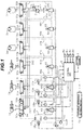
- a hydraulic excavator to which the present invention is applied comprises a hydraulic pump 2, a plurality of hydraulic actuators including a boom cylinder 3a, an arm cylinder 3b, a bucket cylinder 3c, a swing motor 3d and left and right track motors 3e, 3f which are driven by a hydraulic fluid from the hydraulic pump 2, a plurality of control lever units 4a - 4f provided respectively corresponding to the hydraulic actuators 3a - 3f, a plurality of flow control valves 5a - 5f connected between the hydraulic pump 2 and the plurality of hydraulic actuators 3a - 3f for controlling respective flow rates of the hydraulic fluid supplied to the hydraulic actuators 3a - 3f, and a relief valve 6 which is opened when the pressure between the hydraulic pump 2 and the flow control valves 5a - 5f exceeds a preset value.
- the hydraulic excavator is made up of a multi-articulated front device 1A comprising a boom 1a, an arm 1b and a bucket 1c which are each pivotable in the vertical direction, and a body 1B comprising an upper revolving structure 1d which supports the front device 1A, and a lower track structure 1e on which the upper revolving structure 1d is mounted in a revolvable manner.
- the boom 1a of the front device 1A is supported at its base end to a front portion of the upper revolving structure 1d.
- the boom 1a, the arm 1b, the bucket 1c, the upper revolving structure 1d and the lower track structure 1e serve as driven members which are driven respectively by the boom cylinder 3a, the arm cylinder 3b, the bucket cylinder 3c, the swing motor 3d and the left and right track motors 3e, 3f.
- These driven members are operated in accordance with instructions from the control lever units 4a - 4f.
- control lever units 4a - 4f are each of hydraulic pilot type driving corresponding one of the flow control valves 5a - 5f with a pilot pressure.
- Each of the control lever units 4a - 4f comprises a control lever 40 manipulated by the operator, and a pair of pressure reducing valves (not shown) for generating a pilot pressure depending on the input amount and the direction by and in which the control lever 40 is manipulated.
- the pressure reducing valves are connected at primary ports to a pilot pump 43, and at secondary ports to corresponding ones of hydraulic driving sectors 50a, 50b; 51a, 51b; 52a, 52b; 53a, 53b; 54a, 54b; 55a, 55b of the flow control valves through pilot lines 44a, 44b; 45a, 45b; 46a, 46b; 47a, 47b; 48a, 48b; 49a, 49b.
- a slope excavation control system of the present invention is equipped in the hydraulic excavator constructed as explained above.
- the control system comprises a setting device 7 for providing an instruction to set a target excavation plane, angle sensors 8a, 8b, 8c disposed respectively at pivot points of the boom 1a, the arm 1b and the bucket 1c for detecting respective rotational angles thereof as status variables in relation to the position and posture of the front device 1A, a tilting sensor 8d for detecting a tilting angle ⁇ of the body 1B in the longitudinal direction, pressure sensors 60a, 60b; 61a, 61b disposed in the pilot lines 44a, 44b; 45a, 45b connected to the boom and arm control lever units 4a, 4b for detecting respective pilot pressures input from the control lever units 4a, 4b, a front reference 70 provided at an end (prong) of the bucket 1c, an external reference setting switch 71 depressed when the front reference 70 is made aligned with the external reference 80 (described later) through operation of the front device 1A, a control
- the shuttle valve 12 is disposed in the pilot line 44a to select higher one of the pilot pressure in the pilot line 44a and the control pressure delivered from the proportional solenoid valve 10a and then introduce the selected pressure to the hydraulic driving sector 50a of the flow control valve 5a.
- the proportional solenoid valves 10b, 11a, 11b are disposed in the pilot lines 44b, 45a, 45b, respectively, to reduce the pilot pressures in the pilot lines in accordance with the respective electric signals applied thereto and output the reduced pilot pressures.
- an external reference 80 representing a reference position for setting the target excavation plane is provided away from the hydraulic excavator. Since a slope face is set as the target excavation plane in the present invention, the external reference 80 is provided to extend in the direction of advance of the slope face.
- a target slope face setting system is constituted by the setting device 7, the front reference 70, the external reference setting switch 71, the angle sensors 8a, 8b, 8c, the tilting sensor 8d, the external reference 80, and the following functions of the control unit 9.
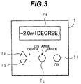
- the setting device 7 comprises, as shown in Fig. 3, a changeover switch 7c for selecting which one of vertical distance, horizontal distance and angle (described later) is to be set for a reference point on the target slope face, up and down buttons 7a, 7b for entering the vertical distance, horizontal distance and angle of the reference point on the target slope face, a display 7e for displaying the entered vertical distance, horizontal distance and angle, and a setting switch 7f for outputting the entered vertical distance, horizontal distance and angle as respective setup signals to the control unit 9 to instruct setting of the target slope face.
- the buttons and so on of the setting device 7 may be provided on a grip of an appropriate control lever.
- the setting of the target slope face may be instructed by any of other suitable methods such as using IC cards, bar codes, and wireless communication.
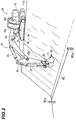
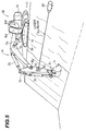
- the external reference 80 is, e.g., a leveling string horizontally stretched between poles 80a to extend in the direction of advance of the target slope face, as shown in Fig. 2.
- the leveling string 80 is often used in the job site to indicate a reference line.
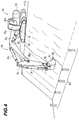
- the external reference may be any other member, e.g., simple poles 81 which are sunk into the ground with intervals therebetween in the direction of advance of the target slope face as shown in Fig. 4, so long as the operator of the hydraulic excavator can confirm the external reference from a cab.
- the front reference 70 is set on the prong of the bucket 1c of the front device 1A as shown in Fig. 2. Although the front reference is preferably set on the prong of the bucket 1c, the front reference may be set in any other suitable position on the front device 1A so long as it locates in such a prescribed position as allowing the operator to easily confirm its alignment with the external reference.
- the external reference setting switch 71 is depressed in the above case when the front device 1A is moved to a position where the front reference 70 is aligned with the leveling string as the external reference 80.
- the position of the external reference 80 is detected and the positional relationship between the body 1B of the hydraulic excavator and the external reference 80 (i.e., the position of the external reference 80 relative to the body) is set through calculation (as described later).
- a laser reference beam oscillator (laser lighthouse tube) 82 which is conventionally used for a survey or other purposes in the job site and emits a spot-like laser beam 84, and as the front reference 70, a laser sensor 83 for detecting the laser beam 84.
- the laser lighthouse tube 82 is installed such that the laser beam 84 is emitted horizontally in the direction of advance of the target slope face.
- the laser lighthouse tube 82 is advantageously installed such that the laser beam 84 locates in a middle position of the target slope face.
- the same function as in the case of using the leveling string or the poles can be achieved by turning on a lamp when the laser beam 84 from the laser lighthouse tube 82 is detected by the laser sensor 83, and depressing the external reference setting switch 71 upon the operator confirming turning-on of the lamp.
- the target slop face may be formed by positioning the body at the bottom of the slope and moving the bucket to scrape down earth from above, as shown in Fig. 6.
- the leveling string 80 as the external reference is provided at the top of the slope in Fig. 6, but it may be provided at the bottom of the slope.
- a laser lighthouse tube may be provided in a middle position of the target slope face, as mentioned above.
- a slope face to be formed by excavation often does not lie in one plane, but is curved in the direction of advance of the slope face.
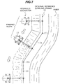
- Fig. 7 shows one example of such a case.
- a slope is formed in a bank extending along a river.
- the bank curves corresponding to curving of the river; hence the slope formed by excavation is also required to curve in the direction of advance of the target slope face following a curve of the bank.
- the external reference 80 is also provided so as to curve along the target slope face curved in the direction of advance thereof.
- the poles 80a are sunk into the ground at appropriate corners and a leveling string is stretched between the poles 80a.
- the front reference 70 be disposed as close as to the end of the bucket 1c to such an extent that working is not interfered, and aligned with the external reference 80 in a position near the end of the bucket 1c which actually acts on earth.
- the external reference setting switch 71 may be incorporated in the setting device 7.
- the control unit 9 sets a target slope face by using the setup signal of the setting device 7 and the detection signals of the external reference setting switch 71, the angle sensors 8a, 8b, 8c and the tilting sensor 8d.
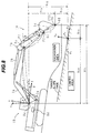
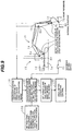
- a manner of setting a target slope face by the control unit 9 and summary of processing functions of the control unit 9 will now be described with reference to Figs. 8 and 9.
- a leveling string for example, is first stretched as the external reference 80, as described above, away from the body of a hydraulic excavator to extend in the direction of advance of the target slope face, as shown in Figs. 2 and 8.
- the operator enters a vertical distance hry and a horizontal distance hrx from the external reference 80 to a reference point Ps on a target slope face to be set, as well as an angle ⁇ r of the target slope face relative to the horizontal by using the setting device 7, thus setting the positional relationship between the external reference 80 and the target slope face based on the vertical distance hry , the horizontal distance hrx and the angle ⁇ r.
- the target slope face is set on the basis of the position of the external reference 80.
- This setting is executed by a processing function of first setting means 100 of the control unit 9 shown in Fig. 9.
- the vertical distance and the horizontal distance from the external reference 80 to the reference point on the target slope and the angle of the target slope face are set in the first setting means 100 as follows. A place where the external reference is to be installed is decided, and the vertical distance and the horizontal distance from the external reference to the reference point on the target slope and the angle of the target slope face are determined by referring to the working drawings, etc. beforehand.
- the operator inputs numeral values those parameters by using the changeover switch 7c and the buttons 7a, 7b of the setting device 7.
- the operator depresses the setting switch 7f for decision.
- the control unit 9 stores those vertical distance, the horizontal distance and angle as hry , hrx and ⁇ r, respectively.
- a target slope face is set in accordance with the positional relationship on the basis of the current body position of the hydraulic excavator.
- the operator first moves the front device 1A so that the front reference 70 set to the prong of the bucket 1c of the front device 1A is aligned with the external reference 80.
- the operator depresses the external reference setting switch 71.
- the current position and posture of the front device 1A are calculated in the control unit 9 by a processing function of first calculating means 120, shown in Fig. 9, based on the signals of the angle sensors 8a, 8b, 8c and the tilting sensor 8d.
- a vertical distance hfy and a horizontal distance hfx from the center O of the body to the external reference 80 are calculated as the positional relationship between the body 1B and the external reference 80 by a processing function of second calculating means 140, shown in Fig. 9, based on information about the position and posture of the front device 1A obtained by the first calculating means 120 at that time.
- a vertical distance hsy and a horizontal distance hsx from the body center O to the reference point Ps on the target slope face are calculated from the previously set vertical distance hry and the horizontal distance hrx (i.e., the positional relationship between the external reference 80 and the excavation area). Then, the vertical distance hsy the horizontal distance hsx , and the angle ⁇ r input by the setting device 7 are set as defining the target slope face on the basis of the body 1B of the hydraulic excavator by a processing function of second setting means 160 shown in Fig. 9.
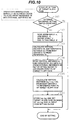
- the operator manipulates the control levers 40 (see Fig. 1) to move the front device 1A so that the front reference 70 is aligned with the external reference 80. Then, the control unit 9 determines in step 141 whether the external reference setting switch 71 is depressed by the operator or not. If not depressed, the control unit 9 brings the setting process to an end without changing the setting of the target slope face. If the external reference setting switch 71 is determined in step 141 as being depressed, the control unit 9 goes to step 142.
- step 142 the control unit 9 reads respective angles ⁇ , ⁇ , ⁇ of the boom 1a, the arm 1b and the bucket 1c and a tilting angle ⁇ of the body 1B from the angle sensors 8a, 8b, 8c and the tilting sensor 8d which are provided on the front device 1A.
- step 143 the vertical distance hfy and the horizontal distance hsx from the body center O to the front reference 70 taken when the external reference setting switch 71 is depressed (i.e., when the front reference 70 is aligned with the external reference 80), is calculated from the angles ⁇ , ⁇ , ⁇ of the boom, the arm and the bucket and the tilting angle ⁇ .
- L1 represents a distance from the joint point between the boom 1a and the body 1B (i.e., the point where the boom angle sensor 8a is mounted), namely the body center O, to the joint point P1 between the boom and the arm.
- a value of the distance L1 is known and stored in the control unit 9 beforehand.
- L2 represents a length from the joint point P1 between the boom and the arm to the joint point P2 between the arm and the bucket, and is stored in the control unit 9 beforehand.
- hcy L3 x cos(( ⁇ - ⁇ ) + ⁇ + ⁇ )
- hcx L3 x sin(( ⁇ - ⁇ ) + ⁇ + ⁇ )
- L3 represents a length from the joint point P2 between the arm and the bucket to the prong P3 of the bucket, and is stored in the control unit 9 beforehand.
- control unit 9 goes to step 144 for reading the vertical distance hry and the horizontal distance hrx from the external reference 80 to the reference point on the target slope face which has been set by using the setting device 7.
- step 161 the control unit 9 stores the vertical distance hsy and the horizontal distance hsx which have been calculated in step 145 for the reference point on the target slope face, and sets the target slope face from those distances hsy , hsx and the angle ⁇ r input from the setting device 7 on the basis of the body.
- the steps 141 - 145 correspond to the processing function of the second calculating means 140 shown in Fig. 9, and the step 161 corresponds to the processing function of the second setting means 160 shown in Fig. 9.
- the hydraulic excavator starts excavation work under the area limiting excavation control shown in block 180 of Fig. 9 to form a slope in match with the target slop face by excavation carried out in the current position.
- the body of the hydraulic excavator is moved to a new position in the lateral direction relative to the finished slope as indicated by arrow in Figs. 4 - 7.
- the above-mentioned steps are executed again by the second calculating means 140 and the second setting means 160.
- the front reference 70 is aligned with the external reference 80 and the external reference setting switch 71 is depressed to set a target slope face on the basis of the body 1B in the new position after movement.
- the hydraulic excavator carries out excavation work under the area limiting excavation control to form a slope in match with the target slop face in that position.
- the hydraulic excavator takes such a posture that the lower track structure 1e is oriented parallel to a slope (target slope face) to be formed, as shown in Figs. 4 - 7, and carries out excavation to form the slope in the posture.
- the body is moved in the lateral direction by traveling the excavator in the same posture.
- similar operation can also be achieved by orienting the lower track structure 1e to position perpendicular to the slope, carrying out excavation to form the slope in the posture, and moving the body in the lateral direction by in a manner of shifting the body in parallel relation (i.e., shifting the body transversely by moving the lower track structure 1e forward and backward repeatedly while it is kept in the posture oriented perpendicular to the slope.
- the slope in match with the target slope face is successively formed along the external reference 80 by repeatedly executing the step of moving the hydraulic excavator in the lateral direction, setting a target slope face on the basis of the body in a new position, and forming the slope under the area limiting excavation in that position.
- the control unit 9 includes functions executed by a first target slope face setting portion 9a, a front posture calculating portion 9b, a target cylinder speed calculating portion 9c, a target end speed vector calculating portion 9d, a direction change control portion 9e, a post-modification target cylinder speed calculating portion 9f, a restoration control calculating portion 9g, a post-modification target cylinder speed calculating portion 9h, a target cylinder speed selector 9i, a target pilot pressure calculating portion 9j, a valve command calculating portion 9k, a positional relationship calculating portion 9m, and a second target slope face setting portion 9n.
- the first target slope face setting portion 9a corresponds to the first setting means 100 in Fig. 9 and sets the positional relationship between the external reference 80 and the target slope face based on the vertical distance hry and the horizontal distance hrx from the external reference 80 to the reference point Ps on the target slope face, as well as the angle ⁇ r of the target slope face with operation of the setting device 7.
- the front posture calculating portion 9b corresponds to the first calculating means 120 in Fig. 9 and calculates the position and posture of the front device 1A necessary for setting and control based on various dimensions of the front device 1A and the body 1B which are stored in the control unit 9, rotational angles ⁇ , ⁇ , ⁇ detected respectively by the angle sensors 8a, 8b, 8c, and a tilting angle ⁇ detected by the tilting sensor.
- the positional relationship calculating portion 9m corresponds to the second calculating means 140 in Fig. 9 and calculates the vertical distance hsy and the horizontal distance hsx from the body center O to the reference point on the target slope face through the steps 141 - 145 of the process flow shown in Fig. 10.
- the second target slope face setting portion 9n corresponds to the second setting means 160 in Fig. 9 and sets the target slope face in accordance with the positional relationship on the basis of the body 1B of the hydraulic excavator from the aforementioned the vertical distance hsy , the horizontal distance hsx and the angle ⁇ r in the step 161 of the process flow shown in Fig. 10.
- the position and posture of the front device 1A are calculated on an XY-coordinate system with the origin defined by the pivot point of the boom 1a.
- the XY-coordinate system is a rectangular coordinate system fixed on the body 1B and is assumed to lie in a vertical plane.
- the tilting angle ⁇ of the body 1B is detected by the tilting sensor 8d and a detected value of the tilting angle ⁇ is input to the front posture calculating portion 9b so that it can make calculation for the position of the bucket end on an XbYb-coordinate system which is provided by rotating the XY-coordinate system through the angle ⁇ .
- the tilting sensor is not always required when work is started after correcting a tilting of the body if the body is inclined, or when excavation is performed in the work site where the body will not incline.
- the vertical distances hry , hsy , hfy , the horizontal distances hrx , hsx , hfx , etc. are processed after being transformed into respective values on the XbYb-coordinate system.
- the target cylinder speed calculating portion 9c receives the detection signals of the pressure sensors 60a, 60b; 61a, 61b as operation signals input from the control lever units 4a, 4b. From the operations signals (pilot pressures), the calculating portion 9c calculates target supply flow rates through the flow control valves 5a, 5b (target speeds of the boom cylinder 3a and the arm cylinder 3b).
- the target end speed vector calculating portion 9d determines a target speed vector Vc at the end of the bucket 1c from the position of the bucket end determined by the front posture calculating portion 9b, the target cylinder speed determined by the target cylinder speed calculating portion 9c, and the various dimensions, such as L1, L2 and L3, stored in the control unit 9. At this time, the target speed vector Vc is calculated as values on an XaYa-coordinate system shown in Fig. 8.
- the XaYa-coordinate system is defined by setting, as the origin thereof, a point on the XbYb-coordinate system given by the horizontal distance hsx and the vertical distance hsy from the body center O to the reference point on the target slope face which are determined by the second target slope face setting portion 9n, and then inclining the XaYa-coordinate system by the angle ⁇ r of the target slope face with respect to the XbYb-coordinate system so that the Xa-coordinate axis lies in the slope face.
- an Xa-coordinate component Vcx of the target speed vector Vc on the XaYa-coordinate system represents a vector component of the target speed vector Vc in the direction parallel to the target slope face
- a Yc-coordinate component Vcy thereof represents a vector component thereof in the direction vertical to the target slope face.
- the direction change control portion 9e modifies the vertical vector component such that it is gradually reduced as the bucket end comes closer to the target slope face.
- a vector (reversed vector) being smaller than the vector component Vcy in the vertical direction and orienting away from the target slope face is added to the vector component Vcy.
- the vertical vector component Vcy of the target speed vector Vc is reduced such that the amount of reduction in the vector component Vcy is increased as a distance Ya decreases.
- the target speed vector Vc is modified into a target speed vector Vca.
- the range of a distance Ya1 from the target slope face can be called a direction change area or a slowdown area.
- Fig. 12 shows one example of a path along which the end of the bucket 1c is moved when the direction change control is performed as per the above-described target speed vector Vca after modification.
- the target speed vector Vc is oriented downward obliquely and constant, its parallel component Vcx remains the same and its vertical component Vcy is gradually reduced as the end of the bucket 1c comes closer to the target slope face (i.e., as the distance Ya decreases).
- the target speed vector Vca after modification is a resultant of both the parallel and vertical components, the path is in the form of a curved line which is curved to become parallel by degrees while approaching the target slope face, as shown in Fig. 9.
- the vertical vector component Vcy of the target speed vector Vc becomes 0 and the target speed vector Vca after modification coincides with Vcx.
- the post-modification target cylinder speed calculating portion 9f calculates target cylinder speeds of the boom cylinder 3a and the arm cylinder 3b from the target speed vector after modification determined by the direction change control portion 9e. This process is a reversal of the calculation executed by the target end speed vector calculating portion 9d.
- the target speed vector is modified depending on the distance from the target slope face so that the bucket end is returned to the inside of the target slope face.
- a vector (reversed vector) being larger than the vector component Vcy in the vertical direction and orienting toward the target slope face is added to the vector component Vcy.
- Fig. 13 shows one example of a path along which the end of the bucket 1c is moved when the restoration control is performed as per the above-described target speed vector Vca after modification.
- the target speed vector Vc is oriented downward obliquely and constant, its parallel component Vcx remains the same and a restoration vector - KYa is proportional to the distance Ya such that a vertical component is gradually reduced as the end of the bucket 1c comes closer to the target slope face (i.e., as the distance Ya decreases).
- the target speed vector Vca after modification is a resultant of both the parallel and vertical components, the path is in the form of a curved line which is curved to become parallel by degrees while approaching the target slope face, as shown in Fig. 13. On the target slope face, the target speed vector Vca after modification coincides with Vcx.
- the restoration control portion 9g since the end of the bucket 1c is controlled to return to the inside of the target slope face by the restoration control portion 9g, a restoration area is defined outside the target slope face.
- the restoration control the movement of the end of the bucket 1c toward the target slope face is also slowed down and, eventually, the direction in which the end of the bucket 1c is moving is converted into the direction along the target slope face.
- the restoration control can also be called direction change control.
- the post-modification target cylinder speed calculating portion 9h calculates target cylinder speeds of the boom cylinder 3a and the arm cylinder 3b from the target speed vector after modification determined by the restoration control portion 9g. This process is a reversal of the calculation executed by the target end speed vector calculating portion 9d.
- the directions in which the boom cylinder and the arm cylinder are required to be operated to achieve the restoration control are selected and the target cylinder speeds in the selected operating directions are calculated. Since the bucket end is returned to the set area by raising the boom 1a in the restoration control, the direction of raising the boom 1a is always included.
- the combination of boom-up and any other mode is also determined in accordance with the control software.
- the target cylinder speed selector 9i selects larger one (maximum value) of a value of the target cylinder speed determined by the target cylinder speed calculating portion 9f for the direction change control and a value of the target cylinder speed determined by the target cylinder speed calculating portion 9h for the restoration control, and then sets the selected value as a target cylinder speed to be output.
- the target pilot pressure calculating portion 9j calculates, as the target pilot pressures, target pilot pressures to be produced in the pilot lines 44a, 44b; 45a, 45b.
- the valve command calculating portion 9k calculates command values corresponding to the target pilot pressures calculated by the target pilot pressure calculating portion 9j, and outputs electric signals corresponding to the command values to the proportional solenoid valves 10a, 10b, 11a, 11b.
- a second embodiment of the present invention will be described with reference to Figs. 15 and 16.
- This second embodiment intends to set the positional relationship between the external reference 80 and the target slope face by a direct teaching method, the setting being made by the first setting means 100 (see Fig. 9) in the above first embodiment. Note that an angle of the target slope face is input and set from the setting device 7.
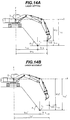
- the vertical distance hry and the horizontal distance hrx from the external reference 80 to the reference point Ps on the target slope face are set in the first setting means 100 by using the up and down buttons 7a, 7b (see Fig. 3) of the setting device 7.
- the operator manipulates the control levers to move the end of the bucket 1c to a position to be set, as indicated by two-dot-chain lines in Fig. 15, and sets the vertical distance hry and the horizontal distance hrx by direct teaching of that position.
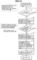
- Fig. 16 shows a process flow of a method of setting the target slope face by direct teaching.
- blocks (1) and (2) circumscribed by broken lines represent manipulations that must be performed by the operator of the hydraulic excavator.
- the operator manipulates the control levers to move the front device 1A so that the end of the bucket 1c comes to the reference point Ps on the target slope face.
- the operator depresses the setting switch 7f (see Fig. 3) of the setting device 7.
- the control unit 9 determines, in step 190, whether the setting switch 7f is depressed or not. If not depressed, the control unit 9 repeats step 190. If the setting switch 7f is depressed, the control unit 9 goes to step 191.
- step 191 the control unit calculates a vertical distance hsy and a horizontal distance hsx from the body center O to the end of the bucket 1c based on the posture of the front device 1A at that time.
- the operator manipulates the control levers again to move the front device 1A so that the front reference 70 (bucket prong) is aligned with the external reference 80.
- control unit repetitively determines in step 192 whether the external reference setting switch 71 is depressed or not. If the external reference setting switch 71 is depressed by the operator upon the front reference 70 being aligned with the external reference 80, the control unit goes to step 193.
- step 193 the control unit calculates a vertical distance hfy and a horizontal distance hfx from the body center O to the front reference 70 based on the posture of the front device 1A at that time.
- step 195 the setting is ended by storing the vertical distance hry and the horizontal distance hrx thus determined, as well as an angle ⁇ r input from the setting devise 7.
- the target slope face is set by direct teaching, it is possible to precisely set a desired target slope face depending on work situations.
- the vertical distance hry or the horizontal distance hrx for the reference point are set by the first setting means 100 shown in Fig. 9 upon the operator manipulating the control levers to move the end of the bucket 1c to the reference point on the target slope face for direct teaching of the position of the reference point, and the angle of the target slope face is set as an angle value input from the setting device 7.
- an angle ⁇ r of the target slope face is also set by direct teaching by directly teaching two points Ps1, Ps2 on the target slope face.
- the bucket end is placed to each of the two points Ps1, Ps2 on the slope face as shown in Fig. 17, and the setting switch 7f is depressed at each point.
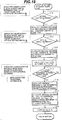
- the control unit calculates and stores respective positions (coordinate values Xps1, Yps1) and (coordinate values Xps2, Yps2) of the two points through steps 200 - 203 shown in Fig. 18.
- steps 205 - 207 are executed for the external reference 80 as with the above case of setting the angle with the setting device 7, thereby calculating a horizontal distance hrx and a vertical distance hry from the external reference 80 to the point Ps1.
- the present invention provides the following advantages.
Landscapes
- Engineering & Computer Science (AREA)
- Mining & Mineral Resources (AREA)
- Civil Engineering (AREA)
- General Engineering & Computer Science (AREA)
- Structural Engineering (AREA)
- Mechanical Engineering (AREA)
- Life Sciences & Earth Sciences (AREA)
- General Life Sciences & Earth Sciences (AREA)
- Paleontology (AREA)
- Operation Control Of Excavators (AREA)
Applications Claiming Priority (3)
| Application Number | Priority Date | Filing Date | Title |
|---|---|---|---|
| JP2903797 | 1997-02-13 | ||
| JP29037/97 | 1997-02-13 | ||
| PCT/JP1998/000559 WO1998036131A1 (fr) | 1997-02-13 | 1998-02-12 | Controleur de creusement de pente de pelle hydraulique, dispositif d'etablissement de la pente cible et procede de formation d'un creusement en pente |
Publications (2)
| Publication Number | Publication Date |
|---|---|
| EP0902131A1 true EP0902131A1 (fr) | 1999-03-17 |
| EP0902131A4 EP0902131A4 (fr) | 2000-06-07 |
Family
ID=12265215
Family Applications (1)
| Application Number | Title | Priority Date | Filing Date |
|---|---|---|---|
| EP98902193A Withdrawn EP0902131A4 (fr) | 1997-02-13 | 1998-02-12 | Controleur de creusement de pente de pelle hydraulique, dispositif d'etablissement de la pente cible et procede de formation d'un creusement en pente |
Country Status (5)
| Country | Link |
|---|---|
| US (1) | US6076029A (fr) |
| EP (1) | EP0902131A4 (fr) |
| KR (1) | KR100353566B1 (fr) |
| CN (1) | CN1192148C (fr) |
| WO (1) | WO1998036131A1 (fr) |
Cited By (4)
| Publication number | Priority date | Publication date | Assignee | Title |
|---|---|---|---|---|
| US6532409B1 (en) | 1999-10-01 | 2003-03-11 | Hitachi Construction Machinery Co., Ltd. | Target excavation surface setting device for excavation machine, recording medium therefor and display unit |
| EP2860315A4 (fr) * | 2012-06-08 | 2016-01-06 | Sumitomo Heavy Industries | Dispositif de commande et procédé de commande d'excavateur |
| EP3733983A4 (fr) * | 2017-12-26 | 2021-11-24 | Hitachi Construction Machinery Co., Ltd. | Engin de chantier |
| EP3951079A4 (fr) * | 2019-03-29 | 2022-06-08 | Sumitomo Construction Machinery Co., Ltd. | Pelle |
Families Citing this family (60)
| Publication number | Priority date | Publication date | Assignee | Title |
|---|---|---|---|---|
| KR100656036B1 (ko) * | 1998-12-04 | 2006-12-08 | 신갸타피라 미쓰비시 가부시키가이샤 | 건설기계 |
| US6275758B1 (en) * | 1999-06-29 | 2001-08-14 | Caterpillar Inc. | Method and apparatus for determining a cross slope of a surface |
| WO2004027164A1 (fr) * | 2002-09-17 | 2004-04-01 | Hitachi Construction Machinery Co., Ltd. | Appareil d'apprentissage de creusement pour une machine de construction |
| WO2005024144A1 (fr) * | 2003-09-02 | 2005-03-17 | Komatsu Ltd. | Dispositif d'instruction de cible de construction |
| US6845311B1 (en) | 2003-11-04 | 2005-01-18 | Caterpillar Inc. | Site profile based control system and method for controlling a work implement |
| US7079931B2 (en) * | 2003-12-10 | 2006-07-18 | Caterpillar Inc. | Positioning system for an excavating work machine |
| SE526989C2 (sv) * | 2004-04-19 | 2005-11-29 | Volvo Constr Equip Holding Se | Metod för skakning av arbetsredskap |
| JP4248579B2 (ja) * | 2004-09-24 | 2009-04-02 | 株式会社小松製作所 | 旋回制御装置、旋回制御方法、および建設機械 |
| US7293376B2 (en) * | 2004-11-23 | 2007-11-13 | Caterpillar Inc. | Grading control system |
| US20060225310A1 (en) * | 2005-04-12 | 2006-10-12 | Koch Roger D | Work machine alignment system and method of maintaining alignment of a work machine |
| US7734398B2 (en) * | 2006-07-31 | 2010-06-08 | Caterpillar Inc. | System for automated excavation contour control |
| KR100934947B1 (ko) * | 2007-10-02 | 2010-01-06 | 볼보 컨스트럭션 이키프먼트 홀딩 스웨덴 에이비 | 레벨링 수단이 구비된 중장비의 영상표시 시스템 |
| US7881845B2 (en) * | 2007-12-19 | 2011-02-01 | Caterpillar Trimble Control Technologies Llc | Loader and loader control system |
| US7975410B2 (en) * | 2008-05-30 | 2011-07-12 | Caterpillar Inc. | Adaptive excavation control system having adjustable swing stops |
| JP5009269B2 (ja) * | 2008-11-12 | 2012-08-22 | 日立建機株式会社 | 油圧ショベルの表示装置 |
| WO2010101233A1 (fr) * | 2009-03-06 | 2010-09-10 | 株式会社小松製作所 | Machine de construction, procédé de commande de machine de construction, et programme pour entraîner l'exécution du procédé par un ordinateur |
| DE102009018070A1 (de) * | 2009-04-20 | 2010-10-21 | Robert Bosch Gmbh | Mobile Arbeitsmaschine mit einer Positionsregeleinrichtung eines Arbeitsarms und Verfahren zur Positionregelung eines Arbeitsarms einer mobilen Arbeitsmaschine |
| JP5059953B2 (ja) * | 2011-02-22 | 2012-10-31 | 株式会社小松製作所 | 油圧ショベルの作業可能範囲表示装置とその制御方法 |
| CL2012000933A1 (es) * | 2011-04-14 | 2014-07-25 | Harnischfeger Tech Inc | Un metodo y una pala de cable para la generacion de un trayecto ideal, comprende: un motor de oscilacion, un motor de izaje, un motor de avance, un cucharon para excavar y vaciar materiales y, posicionar la pala por medio de la operacion del motor de izaje, el motor de avance y el motor de oscilacion y; un controlador que incluye un modulo generador de un trayecto ideal. |
| JP6025372B2 (ja) * | 2012-04-11 | 2016-11-16 | 株式会社小松製作所 | 油圧ショベルの掘削制御システム及び掘削制御方法 |
| US8689471B2 (en) | 2012-06-19 | 2014-04-08 | Caterpillar Trimble Control Technologies Llc | Method and system for controlling an excavator |
| CN102864800A (zh) * | 2012-10-23 | 2013-01-09 | 中联重科股份有限公司渭南分公司 | 挖掘机的平推控制方法和控制装置与挖掘机 |
| CN102995679B (zh) * | 2012-12-17 | 2015-10-07 | 潍柴动力股份有限公司 | 一种挖掘机动作控制方法、装置及系统 |
| TWI513993B (zh) | 2013-03-26 | 2015-12-21 | Ind Tech Res Inst | 三軸磁場感測器、製作磁場感測結構的方法與磁場感測電路 |
| KR101471288B1 (ko) * | 2013-05-06 | 2014-12-09 | 현대중공업 주식회사 | 선회밀림방지장치를 구비한 굴삭기 선회장치 |
| JP6209439B2 (ja) * | 2013-12-19 | 2017-10-04 | ナブテスコ株式会社 | 建設機械用方向切換弁、並びに、その開度決定装置、及びその開度決定方法 |
| US9593469B2 (en) | 2013-12-20 | 2017-03-14 | Cnh Industrial America Llc | System and method for controlling a work vehicle based on a monitored tip condition of the vehicle |
| FI125464B (en) * | 2014-03-18 | 2015-10-15 | Novatron Oy | Arrangement and method for positioning the machine |
| WO2014192474A1 (fr) * | 2014-04-24 | 2014-12-04 | 株式会社小松製作所 | Engin de travail |
| WO2015186180A1 (fr) * | 2014-06-02 | 2015-12-10 | 株式会社小松製作所 | Système de commande de machine de construction, machine de construction, et méthode de commande de machine de construction |
| US9388550B2 (en) * | 2014-09-12 | 2016-07-12 | Caterpillar Inc. | System and method for controlling the operation of a machine |
| US10120369B2 (en) * | 2015-01-06 | 2018-11-06 | Joy Global Surface Mining Inc | Controlling a digging attachment along a path or trajectory |
| KR102488448B1 (ko) | 2015-03-27 | 2023-01-12 | 스미토모 겐키 가부시키가이샤 | 쇼벨 |
| JP6522441B2 (ja) * | 2015-06-29 | 2019-05-29 | 日立建機株式会社 | 作業機械の作業支援システム |
| WO2017061910A1 (fr) * | 2015-10-06 | 2017-04-13 | Cpac Systems Ab | Unité de commande permettant de déterminer la position d'un outil dans une machine de travail |
| CN105804148B (zh) * | 2016-03-14 | 2018-09-11 | 柳州柳工挖掘机有限公司 | 防止挖掘机倾翻控制方法及挖掘机 |
| CN106460363B (zh) * | 2016-05-31 | 2019-11-08 | 株式会社小松制作所 | 作业机械的控制系统、作业机械以及作业机械的控制方法 |
| JP6633464B2 (ja) * | 2016-07-06 | 2020-01-22 | 日立建機株式会社 | 作業機械 |
| JP6666209B2 (ja) * | 2016-07-06 | 2020-03-13 | 日立建機株式会社 | 作業機械 |
| CN107780938B (zh) * | 2016-08-30 | 2019-03-05 | 丹东东方测控技术股份有限公司 | 一种实现露天矿挖掘设备控制矿石出矿品位的方法 |
| JP2017008719A (ja) * | 2016-10-20 | 2017-01-12 | 株式会社小松製作所 | 油圧ショベルの掘削制御システム |
| KR101886798B1 (ko) | 2016-11-29 | 2018-08-08 | 가부시키가이샤 고마쓰 세이사쿠쇼 | 작업기 제어 장치 및 작업 기계 |
| JP7001350B2 (ja) * | 2017-02-20 | 2022-01-19 | 株式会社小松製作所 | 作業車両および作業車両の制御方法 |
| JP6581136B2 (ja) * | 2017-03-21 | 2019-09-25 | 日立建機株式会社 | 作業機械 |
| JP7050051B2 (ja) * | 2017-03-30 | 2022-04-07 | 株式会社小松製作所 | 作業車両の制御システム、作業機の軌跡設定方法、及び作業車両 |
| KR102065478B1 (ko) * | 2017-04-10 | 2020-01-13 | 가부시키가이샤 고마쓰 세이사쿠쇼 | 건설 기계 및 제어 방법 |
| EP3722517B1 (fr) | 2017-12-07 | 2023-07-19 | Sumitomo (S.H.I.) Construction Machinery Co., Ltd. | Excavateur |
| CN108398955B (zh) * | 2018-01-18 | 2020-04-07 | 中国矿业大学(北京) | 一种掘进机姿态控制系统及方法 |
| JP7152170B2 (ja) * | 2018-03-28 | 2022-10-12 | 株式会社小松製作所 | 作業車両の制御システム、方法、及び作業車両 |
| US11372405B2 (en) * | 2018-08-06 | 2022-06-28 | Clark Equipment Company | Augmented loader controls |
| JP7141899B2 (ja) * | 2018-09-13 | 2022-09-26 | 日立建機株式会社 | 作業機械 |
| KR102708710B1 (ko) * | 2018-11-14 | 2024-09-20 | 스미도모쥬기가이고교 가부시키가이샤 | 쇼벨, 쇼벨의 제어장치 |
| KR102685684B1 (ko) * | 2018-11-14 | 2024-07-15 | 스미도모쥬기가이고교 가부시키가이샤 | 쇼벨, 쇼벨의 제어장치 |
| KR102785874B1 (ko) | 2019-02-04 | 2025-03-21 | 스미도모쥬기가이고교 가부시키가이샤 | 쇼벨 |
| EP3926103B1 (fr) * | 2019-02-15 | 2025-10-29 | Sumitomo Heavy Industries, Ltd. | Excavatrice |
| EP3951085A4 (fr) * | 2019-03-28 | 2022-08-24 | Sumitomo Construction Machinery Co., Ltd. | Excavatrice et système de construction |
| JP7595636B2 (ja) * | 2019-07-08 | 2024-12-06 | ダンフォス アクチ-セルスカブ | 油圧システム構造及びシステム構造内で使用可能な双方向比例弁 |
| CN111139883B (zh) * | 2019-12-27 | 2021-09-14 | 中铁十七局集团第三工程有限公司 | 挖掘机刷坡作业坡度控制装置及方法 |
| CN117083430A (zh) * | 2021-03-31 | 2023-11-17 | 住友重机械工业株式会社 | 挖土机及挖土机的控制装置 |
| CN119956839B (zh) * | 2025-04-11 | 2025-07-08 | 山西金地源地质科技有限公司 | 一种狭小作业基坑的挖土装置及挖土方法 |
Family Cites Families (10)
| Publication number | Priority date | Publication date | Assignee | Title |
|---|---|---|---|---|
| US4829418A (en) * | 1987-04-24 | 1989-05-09 | Laser Alignment, Inc. | Apparatus and method for controlling a hydraulic excavator |
| JPH03295934A (ja) * | 1990-04-13 | 1991-12-26 | Shimizu Corp | 切盛土工事における法面整形施工法及び施工装置 |
| JP2889945B2 (ja) * | 1990-04-13 | 1999-05-10 | 株式会社小松製作所 | レーザ光を用いた油圧式パワーショベルの直線掘削制御方法 |
| JPH04106229A (ja) * | 1990-08-27 | 1992-04-08 | Hitachi Constr Mach Co Ltd | 掘削機の掘削深さ検出装置 |
| JP2696442B2 (ja) * | 1991-07-26 | 1998-01-14 | 株式会社フジタ | 自動法面掘削システム |
| JPH06146334A (ja) * | 1992-11-17 | 1994-05-27 | Taisei Corp | 掘削方法 |
| DE69511033T2 (de) * | 1994-04-28 | 2000-02-17 | Hitachi Construction Machinery Co., Ltd. | Baggersteuervorrichtung mit einem baggerbereich-begrenzer für baumaschinen |
| KR0173835B1 (ko) * | 1994-06-01 | 1999-02-18 | 오까다 하지모 | 건설기계의 영역제한 굴삭제어장치 |
| JP3497910B2 (ja) * | 1995-03-13 | 2004-02-16 | 日立建機株式会社 | 建設機械の領域制限掘削制御の掘削領域設定装置 |
| JP3522878B2 (ja) * | 1995-03-13 | 2004-04-26 | 日立建機株式会社 | 建設機械の領域制限掘削制御の掘削領域設定装置 |
-
1998
- 1998-02-12 CN CNB988001233A patent/CN1192148C/zh not_active Expired - Fee Related
- 1998-02-12 US US09/155,887 patent/US6076029A/en not_active Expired - Fee Related
- 1998-02-12 EP EP98902193A patent/EP0902131A4/fr not_active Withdrawn
- 1998-02-12 WO PCT/JP1998/000559 patent/WO1998036131A1/fr not_active Ceased
- 1998-02-12 KR KR10-1998-0707798A patent/KR100353566B1/ko not_active Expired - Fee Related
Cited By (7)
| Publication number | Priority date | Publication date | Assignee | Title |
|---|---|---|---|---|
| US6532409B1 (en) | 1999-10-01 | 2003-03-11 | Hitachi Construction Machinery Co., Ltd. | Target excavation surface setting device for excavation machine, recording medium therefor and display unit |
| EP1186720A4 (fr) * | 1999-10-01 | 2008-11-19 | Hitachi Construction Machinery | Dispositif de delimitation de la surface d'excavation cible pour engin excavateur, support d'enregistrement prevu a cet effet et unite d'affichage |
| EP2860315A4 (fr) * | 2012-06-08 | 2016-01-06 | Sumitomo Heavy Industries | Dispositif de commande et procédé de commande d'excavateur |
| US9915054B2 (en) | 2012-06-08 | 2018-03-13 | Sumitomo Heavy Industries, Ltd. | Shovel control method and shovel control device |
| US11248361B2 (en) | 2012-06-08 | 2022-02-15 | Sumitomo Heavy Industries, Ltd. | Shovel control method and shovel control device |
| EP3733983A4 (fr) * | 2017-12-26 | 2021-11-24 | Hitachi Construction Machinery Co., Ltd. | Engin de chantier |
| EP3951079A4 (fr) * | 2019-03-29 | 2022-06-08 | Sumitomo Construction Machinery Co., Ltd. | Pelle |
Also Published As
| Publication number | Publication date |
|---|---|
| EP0902131A4 (fr) | 2000-06-07 |
| CN1192148C (zh) | 2005-03-09 |
| CN1216080A (zh) | 1999-05-05 |
| KR100353566B1 (ko) | 2003-01-06 |
| KR20000064826A (ko) | 2000-11-06 |
| US6076029A (en) | 2000-06-13 |
| WO1998036131A1 (fr) | 1998-08-20 |
Similar Documents
| Publication | Publication Date | Title |
|---|---|---|
| US6076029A (en) | Slope excavation controller of hydraulic shovel, target slope setting device and slope excavation forming method | |
| US5960378A (en) | Excavation area setting system for area limiting excavation control in construction machines | |
| EP0790355B1 (fr) | Appareil de definition d'une zone a excaver permettant de controler l'excavation d'une zone limitee par une machine de construction | |
| US5752333A (en) | Area limiting excavation control system for construction machines | |
| EP0707118B1 (fr) | Dispositif de commande d'excavation a limitation de surface de travail pour engin de terrassement | |
| EP0803614B1 (fr) | Dispositif de commande du lieu géométrique pour des machines de chantier | |
| JP6526321B2 (ja) | 作業機械 | |
| EP0979901B1 (fr) | Dispositif permettant de reguler un puits de fondation a l'aide d'une machine de construction | |
| EP0711876A1 (fr) | Dispositif de commande d'excavation a limitation de surface pour engins de terrassement | |
| JP7669187B2 (ja) | 積込機械の制御システム及び制御方法 | |
| JP2003105795A (ja) | 油圧ショベルの掘削制御装置 | |
| WO2024106536A1 (fr) | Dispositif de commande pour machine de chargement, dispositif de commande à distance et procédé de commande | |
| JPH108490A (ja) | 建設機械のフロント制御装置及び領域設定方法 | |
| JP3497910B2 (ja) | 建設機械の領域制限掘削制御の掘削領域設定装置 | |
| JPH11350537A (ja) | 油圧作業機械の制御装置 | |
| JP3522878B2 (ja) | 建設機械の領域制限掘削制御の掘削領域設定装置 | |
| JP3713358B2 (ja) | 建設機械のフロント制御装置 | |
| JP3682352B2 (ja) | 建設機械のフロント制御装置 | |
| JPS63194030A (ja) | パワ−シヨベルの作業機制御方法および装置 | |
| JPWO1998036131A1 (ja) | 油圧ショベルの法面掘削制御装置、目標法面設定装置及び法面掘削形成方法 | |
| JP2000328606A (ja) | 建設機械の作業機制御装置 | |
| JP2023151687A (ja) | ショベル | |
| JPH11336115A (ja) | 多関節作業機械の制御装置 | |
| WO2025142344A1 (fr) | Système de commande et machine de travail | |
| JPH093958A (ja) | 建設機械の作業範囲制限制御装置 |
Legal Events
| Date | Code | Title | Description |
|---|---|---|---|
| PUAI | Public reference made under article 153(3) epc to a published international application that has entered the european phase |
Free format text: ORIGINAL CODE: 0009012 |
|
| 17P | Request for examination filed |
Effective date: 19981103 |
|
| AK | Designated contracting states |
Kind code of ref document: A1 Designated state(s): DE FR GB IT SE |
|
| A4 | Supplementary search report drawn up and despatched |
Effective date: 20000427 |
|
| AK | Designated contracting states |
Kind code of ref document: A4 Designated state(s): DE FR GB IT SE |
|
| 17Q | First examination report despatched |
Effective date: 20030709 |
|
| GRAP | Despatch of communication of intention to grant a patent |
Free format text: ORIGINAL CODE: EPIDOSNIGR1 |
|
| STAA | Information on the status of an ep patent application or granted ep patent |
Free format text: STATUS: THE APPLICATION IS DEEMED TO BE WITHDRAWN |
|
| 18D | Application deemed to be withdrawn |
Effective date: 20050712 |