EP0902143A2 - Locking mechanism of door locking apparatus for motor vehicle - Google Patents
Locking mechanism of door locking apparatus for motor vehicle Download PDFInfo
- Publication number
- EP0902143A2 EP0902143A2 EP98116883A EP98116883A EP0902143A2 EP 0902143 A2 EP0902143 A2 EP 0902143A2 EP 98116883 A EP98116883 A EP 98116883A EP 98116883 A EP98116883 A EP 98116883A EP 0902143 A2 EP0902143 A2 EP 0902143A2
- Authority
- EP
- European Patent Office
- Prior art keywords
- condition
- locking
- door
- lock lever
- reinforcement
- Prior art date
- Legal status (The legal status is an assumption and is not a legal conclusion. Google has not performed a legal analysis and makes no representation as to the accuracy of the status listed.)
- Granted
Links
Images


Classifications
-
- E—FIXED CONSTRUCTIONS
- E05—LOCKS; KEYS; WINDOW OR DOOR FITTINGS; SAFES
- E05B—LOCKS; ACCESSORIES THEREFOR; HANDCUFFS
- E05B77/00—Vehicle locks characterised by special functions or purposes
- E05B77/02—Vehicle locks characterised by special functions or purposes for accident situations
- E05B77/12—Automatic locking or unlocking at the moment of collision
-
- Y—GENERAL TAGGING OF NEW TECHNOLOGICAL DEVELOPMENTS; GENERAL TAGGING OF CROSS-SECTIONAL TECHNOLOGIES SPANNING OVER SEVERAL SECTIONS OF THE IPC; TECHNICAL SUBJECTS COVERED BY FORMER USPC CROSS-REFERENCE ART COLLECTIONS [XRACs] AND DIGESTS
- Y10—TECHNICAL SUBJECTS COVERED BY FORMER USPC
- Y10S—TECHNICAL SUBJECTS COVERED BY FORMER USPC CROSS-REFERENCE ART COLLECTIONS [XRACs] AND DIGESTS
- Y10S292/00—Closure fasteners
- Y10S292/65—Emergency or safety
Definitions
- the present invention relates to a door locking apparatus for a motor vehicle and more particularly to a locking mechanism of a door locking apparatus.
- the door locking apparatus comprises a latch plate engaging with a striker secured to the vehicle body, a detent lever engaging with a pawl of the latch plate to hold an engagement condition with the latch plate, an operating lever for operating the detent lever in the direction of disengaging with the pawl of the latch plate when an outer handle or inner handle is operated and a locking mechanism for disabling a disengagement with the pawl even when the outer or inner handle is operated.
- a so-called “idle lock type” locking mechanism has been generally used.
- This type of the locking mechanism is constituted such that an unlocking condition where the operating lever is connected with the detent lever is changed over to a locking condition where the operating lever is disconnected with the detent lever by use of a lock lever.
- the changeover from the unlocking condition to the locking condition of the lock lever is performed by operating an inner lock lever from inside of the vehicle or turning a key from outside of the vehicle.
- the locking mechanism of the door locking apparatus When the locking mechanism of the door locking apparatus is in the locking condition, it is constituted such that the door will not open from outside of the vehicle. This causes a problem that a passenger trapped in a car can not be rescued readily due to the broken locking mechanism when the vehicle has a collision, especially when it has a side impact. Further, even if the locking mechanism is in the unlocking condition, there is a possibility that the locking mechanism turns to the locking condition due to an external force applied to the engaging mechanism between the inner lock lever and the lock lever, resulting in taking time to rescue the passenger.
- JP-U- 4-98972 discloses a technique in which a door lock switch is provided with an impact sensing device for changing over the locking mechanism to the unlocking condition, when a large impact is given to the vehicle body, by returning a movable contact to a fixed contact side.
- JP-U- 6-32648 discloses a technique in which, when an impact is detected by an impact sensor, a control section raises a signal for operating an actuator and the locking mechanism is changed over into the unlocking condition by the operation of this actuator.
- the object of the invention is to provide a door locking apparatus capable of holding a door in an unlocking condition so as to rescue a passenger readily therethrough when the door is deformed by a large lateral impact applied thereto.
- the door locking apparatus includes a reinforcement provided in door panels, a lock lever for changing over the vehicle door either in a locking condition or in an unlocking condition, a bracket for securing the reinforcement to the door panels, a cam-shaped projection provided on the bracket and an end portion of the lock lever opposedly close to the cam-shaped projection for rotating the lock lever so as to change from the locking condition to the unlocking condition, when the reinforcement is deformed inwardly and as a result the cam-shaped projection strikes the end portion of the lock lever.
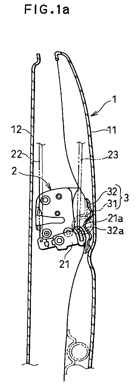
- reference numeral 1 denotes a door of a vehicle which is composed of an outer panel 11 and an inner panel 12.
- the door 1 is hinged at the upper and lower portions of the front end thereof to the body (pillar) and is provided with a door locking apparatus 2 at the rear end thereof.
- the door locking apparatus basically comprises a latch plate engaging with a striker secured to the vehicle body, a detent lever engaging with a pawl of the latch plate to hold an engagement condition with the latch plate, an operating lever for operating the detent lever in the disengaging direction with the pawl of the latch plate when an outer handle or inner handle is operated and a locking mechanism for holding a locking condition, that is, a condition where the engagement with the pawl can not released, even when the outer or inner handle is operated.
- a locking mechanism for holding a locking condition, that is, a condition where the engagement with the pawl can not released, even when the outer or inner handle is operated.
- This type of the locking mechanism has a lock lever 21 for changing over between an unlocking condition in which the operating lever is connected with the detent lever and a locking condition in which the operating lever is disconnected with the detent lever.
- This "idle lock type" locking mechanism is also well known, consequently detailed description and illustrations will be omitted.
- the lock lever 21 is held at a locking position or an unlocking position with a click stop feeling retained by a reversing spring (not shown), respectively and the changeover of the locking lever 21 from the locking position to the unlocking position and vise versa is performed by an operation of an inner lock lever from inside of the vehicle or by an operation of a key from outside of the vehicle.
- reference numeral 22 denotes a rod for interconnecting the inner lock lever with the lock lever 21
- reference numeral 23 denotes a rod for interconnecting the lock lever 21 with a key lock lever (not shown) which is turned by a key operation.
- Numeral 3 denotes a reinforcement provided longitudinally with respect to the door 1 along the inner side of the outer panel 11 for raising a resistance of the door 1 against a side impact to reduce the amount of protrusion due to the deformation of the door 1 towards the passenger compartment.
- the reinforcement 3 is composed of a pipe-shaped beam 31 and brackets 32, 32 for securing the beam 31 to the outer panel 11 at both ends of the beam 31.
- the door locking apparatus 2 is disposed opposedly to the bracket 32 (in this embodiment, the bracket on the rear side of the vehicle).
- the bracket 32 has a cam-shaped projection 32a whose outer surface is opposed to an end portion 21a of the lock lever 21 as shown in Fig. 1a.
- either the contact surface of the cam-shaped projection 32a or that of the end portion 21a of the lock lever 21 or both of them may be coated with synthetic resin for smooth sliding.
- the lock lever 21 itself or the bracket 32 itself may be fabricated of synthetic resin.
- two sets of the reinforcement 3, 3 are provided at the upper and lower portions of the door 1 respectively and the upper one is used for the purpose of the present invention.
- the number of the reinforcement 3 is arbitrary. Any of the bracket 32 can be provided with a cam-shaped projection 32a.
- the locking mechanism is applied to the idle lock type but it may include any type of the locking mechanism which can be changed over between the locking and unlocking conditions by operating the lock lever 21.
- the lock lever when a vehicle has a side impact, the lock lever can easily turn to an unlocking condition, that is, a condition in which the door stay unlocked, by employing existing components without using expensive devices such as an impact sensor or an electric actuator. Further, since the door locking mechanism according to the present invention has a simple construction, a low cost and practicable door locking apparatus having a fail safe unlocking mechanism can be realized.
Landscapes
- Lock And Its Accessories (AREA)
Abstract
Description
JP-U- 6-32648 discloses a technique in which, when an impact is detected by an impact sensor, a control section raises a signal for operating an actuator and the locking mechanism is changed over into the unlocking condition by the operation of this actuator.
Claims (4)
- A vehicle door having an outer panel, an inner panel, a reinforcement provided between said outer and inner panels for absorbing a side impact and a door locking apparatus including a locking mechanism for selectively changing over said vehicle door from a locking condition to an unlocking condition and vise versa, comprising:a moving element moving inwardly in response to said side impact of said reinforcement for generating an inward stroke; andan unlocking means responsive to said inward stroke of said moving element for selectively changing over said locking mechanism from said locking condition to said unlocking condition and for holding said vehicle door in said unlocking condition.
- A vehicle door having an outer panel, an inner panel, a reinforcement provided between said outer and inner panels for absorbing a side impact and a door locking apparatus including a lock lever for selectively changing over said vehicle door from a locking condition to an unlocking condition and vise versa, comprising:a bracket for securing said reinforcement to said outer panel;a cam-shaped projection provided on said bracket and movable inwardly when said reinforcement is deformed; andan end portion of said lock lever opposedly close to said cam-shaped projection for rotating said lock lever in the direction of changing over from said locking condition to said unlocking condition and for holding said vehicle door in said unlocking condition, when said reinforcement is deformed inwardly and as a result said cam-shaped projection strikes said end portion.
- The vehicle door according to claim 2, whereinsaid cam-shaped projection of said bracket has its surface coated with a synthetic resin layer.
- The vehicle door according to claim 2 or 3, whereinsaid end portion of said lock lever has its surface coated with a synthetic resin layer.
Applications Claiming Priority (3)
| Application Number | Priority Date | Filing Date | Title |
|---|---|---|---|
| JP262654/97 | 1997-09-10 | ||
| JP26265497 | 1997-09-10 | ||
| JP26265497A JP3947278B2 (en) | 1997-09-10 | 1997-09-10 | Vehicle door unlock mechanism |
Publications (3)
| Publication Number | Publication Date |
|---|---|
| EP0902143A2 true EP0902143A2 (en) | 1999-03-17 |
| EP0902143A3 EP0902143A3 (en) | 2000-12-27 |
| EP0902143B1 EP0902143B1 (en) | 2006-08-30 |
Family
ID=17378788
Family Applications (1)
| Application Number | Title | Priority Date | Filing Date |
|---|---|---|---|
| EP19980116883 Expired - Lifetime EP0902143B1 (en) | 1997-09-10 | 1998-09-07 | Locking mechanism of door locking apparatus for motor vehicle |
Country Status (4)
| Country | Link |
|---|---|
| US (1) | US6065797A (en) |
| EP (1) | EP0902143B1 (en) |
| JP (1) | JP3947278B2 (en) |
| DE (1) | DE69835724T2 (en) |
Cited By (1)
| Publication number | Priority date | Publication date | Assignee | Title |
|---|---|---|---|---|
| WO2015185819A1 (en) * | 2014-06-05 | 2015-12-10 | Peugeot Citroen Automobiles Sa | Lightened door reinforcing structure |
Families Citing this family (23)
| Publication number | Priority date | Publication date | Assignee | Title |
|---|---|---|---|---|
| US6250711B1 (en) * | 1998-07-31 | 2001-06-26 | Toyota Jidosha Kabushiki Kaisha | Energy absorber securing structure and method |
| DE19908103B4 (en) * | 1999-02-25 | 2006-07-27 | Daimlerchrysler Ag | Opening device for a movable body part of a motor vehicle |
| KR200266242Y1 (en) * | 1999-06-10 | 2002-02-28 | 이계안 | door structure for a vehicle |
| US6382707B1 (en) * | 2000-10-09 | 2002-05-07 | Daimlerchrysler Corporation | Reinforced door assembly for a motor vehicle |
| KR100462484B1 (en) * | 2002-09-03 | 2004-12-17 | 현대자동차주식회사 | Door Unlocking Apparatus for Automobile |
| US7055886B2 (en) * | 2003-03-28 | 2006-06-06 | Shape Corporation | Low-profile high-strength vehicle door beam |
| JP4560776B2 (en) * | 2004-09-10 | 2010-10-13 | スズキ株式会社 | Door open state prevention structure |
| US7648192B2 (en) * | 2005-08-02 | 2010-01-19 | Ford Global Technologies, Llc | Door latch system for automotive vehicle |
| EP1953020B1 (en) * | 2007-02-05 | 2013-12-04 | Mazda Motor Corporation | Door structure of automotive vehicle and assembling method thereof |
| KR100862257B1 (en) | 2007-12-13 | 2008-10-09 | 현대자동차주식회사 | Car door lock prevention device in case of collision |
| US8128151B2 (en) | 2009-09-11 | 2012-03-06 | Toyota Motor Engineering & Manufacturing North America, Inc. | Method and system for disengaging a drive rod in a door after an impact to the door |
| US8235451B2 (en) * | 2009-11-16 | 2012-08-07 | Toyota Motor Engineering & Manufacturing North America, Inc. | Method and system for deforming a drive rod in a door after an impact to the door |
| US8079631B2 (en) * | 2009-11-18 | 2011-12-20 | Toyota Motor Engineering & Manufacturing North America, Inc. | Method and system for guiding a drive rod in a door after an impact to the door |
| JP5403159B2 (en) * | 2010-06-08 | 2014-01-29 | 日産自動車株式会社 | Vehicle door structure |
| US8414038B2 (en) * | 2010-08-12 | 2013-04-09 | Nissan North America, Inc. | Vehicle door latch structure |
| DE102012025053A1 (en) | 2012-12-21 | 2014-06-26 | BROSE SCHLIEßSYSTEME GMBH & CO. KG | Motor vehicle lock |
| US9605449B2 (en) * | 2013-03-25 | 2017-03-28 | Brose Schliesssysteme Gmbh & Co. Kg | Motor vehicle lock |
| DE102013104144A1 (en) * | 2013-04-24 | 2014-10-30 | Dr. Ing. H.C. F. Porsche Aktiengesellschaft | Door structure with a locking element preventing the door unlocking |
| JP6436652B2 (en) * | 2014-05-30 | 2018-12-12 | ダイハツ工業株式会社 | Unlock holding structure for automotive door inner handle |
| US10914101B2 (en) * | 2017-11-01 | 2021-02-09 | Toyota Motor Engineering & Manufacturing North America, Inc. | Door latch assemblies for vehicles including latch release lever blocking structures |
| DE102017221278B4 (en) * | 2017-11-28 | 2026-02-12 | Airbus Operations Gmbh | System for the automatic unlocking of an aircraft door |
| US11060326B2 (en) * | 2018-03-16 | 2021-07-13 | Toyota Motor Engineering & Manufacturing North America, Inc. | Door latch assemblies for vehicles including latch release lever blocking structures |
| US11466478B2 (en) | 2019-07-08 | 2022-10-11 | Toyota Motor Engineering & Manufacturing North America, Inc. | Side impact-initiated door latch locking system |
Family Cites Families (25)
| Publication number | Priority date | Publication date | Assignee | Title |
|---|---|---|---|---|
| US3713691A (en) * | 1971-02-10 | 1973-01-30 | J Bayless | Vehicle door collision plate and latch |
| JPS5527948B2 (en) * | 1972-02-21 | 1980-07-24 | ||
| JPS5811275A (en) * | 1981-07-08 | 1983-01-22 | 日産自動車株式会社 | Apparatus for unlocking door lock of automobile in emergency |
| US4709950A (en) * | 1984-06-21 | 1987-12-01 | American Device Manufacturing Co. | Crash bar door locking device |
| FR2572116B2 (en) * | 1984-10-19 | 1988-09-30 | Leplat Robert | REMOTE LOCKING AND UNLOCKING DEVICE, PARTICULARLY FOR PANIC BAR |
| DE3446519A1 (en) * | 1984-12-20 | 1986-06-26 | Bayerische Motoren Werke AG, 8000 München | Automatic unlocking device on vehicle doors |
| US4829713A (en) * | 1988-04-05 | 1989-05-16 | United Technologies Automotive, Inc. | Guidance receptor cup system for automotive modular door panels |
| DE4015522A1 (en) * | 1989-09-14 | 1991-03-28 | Bosch Gmbh Robert | DEVICE FOR LOCKING AND UNLOCKING CLOSED DOORS TO THE INTERIOR OF A MOTOR VEHICLE |
| US5026100A (en) * | 1989-09-19 | 1991-06-25 | General Dynamics Corporation | Lock release apparatus |
| CA2054577C (en) * | 1991-01-25 | 1996-03-12 | Larry Holt | Module for vehicle door |
| IT1245586B (en) * | 1991-03-25 | 1994-09-29 | Giuseppe Codrino | DEVICE FOR THE CONTROL OF THE CENTRAL LOCKING OF THE DOORS OF A VEHICLE, WITH AUTOMATIC RELEASE OF THE DOORS SAME, IN THE EVENT OF ACCIDENTS |
| JP3027996B2 (en) * | 1991-03-27 | 2000-04-04 | スズキ株式会社 | Automotive door structure |
| JP3029724B2 (en) * | 1991-12-24 | 2000-04-04 | ダイハツ工業株式会社 | Car front door structure |
| SE501812C2 (en) * | 1992-09-25 | 1995-05-22 | Plannja Hardtech Ab | Safety bar in vehicle |
| US5404690A (en) * | 1993-03-26 | 1995-04-11 | Crescive Die & Tool, Inc. | Impact beam assembly method and apparatus |
| JP3185838B2 (en) * | 1994-02-25 | 2001-07-11 | 日産自動車株式会社 | Vehicle door structure |
| JP3763858B2 (en) * | 1995-02-14 | 2006-04-05 | ユニプレス株式会社 | Guard beam for automobile door |
| GB2299309B (en) * | 1995-03-28 | 1999-02-17 | Kiekert Ag | Motor vehicle door |
| US5785376A (en) * | 1995-06-21 | 1998-07-28 | Mascotech Tubular Products, Inc. | Vehicle door beam |
| JP3370218B2 (en) * | 1995-09-04 | 2003-01-27 | アイシン精機株式会社 | Door unlocking device in case of collision |
| DE19546063C1 (en) * | 1995-12-09 | 1997-04-17 | Porsche Ag | Operating device for unlocking at least one pivotable cover of road vehicle |
| KR100194711B1 (en) * | 1995-12-12 | 1999-06-15 | 정몽규 | Shock Absorber of Vehicle Door |
| DE19548562B4 (en) * | 1995-12-23 | 2004-12-16 | Siemens Ag | Device for unlocking the doors of a motor vehicle |
| US5755484A (en) * | 1996-10-28 | 1998-05-26 | Ford Global Technologies, Inc. | Vehicle door intrusion beam |
| US5868456A (en) * | 1997-09-29 | 1999-02-09 | Trim Trends, Inc. | Selectively heat treated side intrusion beams and method for making the same |
-
1997
- 1997-09-10 JP JP26265497A patent/JP3947278B2/en not_active Expired - Fee Related
-
1998
- 1998-08-31 US US09/144,198 patent/US6065797A/en not_active Expired - Fee Related
- 1998-09-07 EP EP19980116883 patent/EP0902143B1/en not_active Expired - Lifetime
- 1998-09-07 DE DE1998635724 patent/DE69835724T2/en not_active Expired - Lifetime
Cited By (2)
| Publication number | Priority date | Publication date | Assignee | Title |
|---|---|---|---|---|
| WO2015185819A1 (en) * | 2014-06-05 | 2015-12-10 | Peugeot Citroen Automobiles Sa | Lightened door reinforcing structure |
| FR3021907A1 (en) * | 2014-06-05 | 2015-12-11 | Peugeot Citroen Automobiles Sa | REINFORCED DOOR REINFORCEMENT STRUCTURE |
Also Published As
| Publication number | Publication date |
|---|---|
| US6065797A (en) | 2000-05-23 |
| JP3947278B2 (en) | 2007-07-18 |
| DE69835724D1 (en) | 2006-10-12 |
| EP0902143B1 (en) | 2006-08-30 |
| EP0902143A3 (en) | 2000-12-27 |
| JPH1181772A (en) | 1999-03-26 |
| DE69835724T2 (en) | 2007-09-20 |
Similar Documents
| Publication | Publication Date | Title |
|---|---|---|
| US6065797A (en) | Locking mechanism of door locking apparatus for motor vehicle | |
| EP0368290B1 (en) | Vehicle door lock system | |
| US5309745A (en) | Interlocking device for doors of a motor vehicle | |
| US20020157435A1 (en) | Locking device | |
| US7021681B2 (en) | Door lock device | |
| JP6213927B2 (en) | Automatic vehicle door lock | |
| CA1106024A (en) | Vehicle security system | |
| JPH09105262A (en) | Central locking device with automobile door lock having samestructure | |
| US6655179B2 (en) | Automotive door lock assembly | |
| US6737758B2 (en) | Motor-vehicle door locking system with quick unlocking | |
| KR20170021996A (en) | A door latch link structure for preventing door opening | |
| KR102940762B1 (en) | Vehicle lock | |
| CN118187582A (en) | Electric door unlocking assembly and vehicle | |
| CN216034109U (en) | Armrest box for vehicle and vehicle | |
| JP3939083B2 (en) | Actuator | |
| JP2020041365A (en) | Vehicle gate opening/closing mechanism | |
| CN113622757A (en) | Motor vehicle lock with anti-theft device | |
| CN113622758A (en) | Motor vehicle lock with anti-theft device | |
| US20260035967A1 (en) | Lock for a motor vehicle | |
| KR200172640Y1 (en) | Door lock prevention device | |
| US20250237095A1 (en) | Lock For a Motor Vehicle, In Particular a Hood or Gate Lock | |
| US5040740A (en) | Dual safety belt retractor with single switch assembly | |
| JP2505423Y2 (en) | Door lock operating device for automobiles | |
| KR100348072B1 (en) | locking release apparatus for door of automobile | |
| KR19990026981A (en) | Speed response door handle operation device of automobile |
Legal Events
| Date | Code | Title | Description |
|---|---|---|---|
| PUAI | Public reference made under article 153(3) epc to a published international application that has entered the european phase |
Free format text: ORIGINAL CODE: 0009012 |
|
| AK | Designated contracting states |
Kind code of ref document: A2 Designated state(s): DE GB |
|
| AX | Request for extension of the european patent |
Free format text: AL;LT;LV;MK;RO;SI |
|
| PUAL | Search report despatched |
Free format text: ORIGINAL CODE: 0009013 |
|
| AK | Designated contracting states |
Kind code of ref document: A3 Designated state(s): AT BE CH CY DE DK ES FI FR GB GR IE IT LI LU MC NL PT SE |
|
| AX | Request for extension of the european patent |
Free format text: AL;LT;LV;MK;RO;SI |
|
| 17P | Request for examination filed |
Effective date: 20010612 |
|
| AKX | Designation fees paid |
Free format text: DE GB |
|
| GRAP | Despatch of communication of intention to grant a patent |
Free format text: ORIGINAL CODE: EPIDOSNIGR1 |
|
| GRAS | Grant fee paid |
Free format text: ORIGINAL CODE: EPIDOSNIGR3 |
|
| GRAA | (expected) grant |
Free format text: ORIGINAL CODE: 0009210 |
|
| AK | Designated contracting states |
Kind code of ref document: B1 Designated state(s): DE GB |
|
| REG | Reference to a national code |
Ref country code: GB Ref legal event code: FG4D |
|
| REF | Corresponds to: |
Ref document number: 69835724 Country of ref document: DE Date of ref document: 20061012 Kind code of ref document: P |
|
| PLBE | No opposition filed within time limit |
Free format text: ORIGINAL CODE: 0009261 |
|
| STAA | Information on the status of an ep patent application or granted ep patent |
Free format text: STATUS: NO OPPOSITION FILED WITHIN TIME LIMIT |
|
| GBPC | Gb: european patent ceased through non-payment of renewal fee |
Effective date: 20061130 |
|
| 26N | No opposition filed |
Effective date: 20070531 |
|
| PG25 | Lapsed in a contracting state [announced via postgrant information from national office to epo] |
Ref country code: GB Free format text: LAPSE BECAUSE OF NON-PAYMENT OF DUE FEES Effective date: 20061130 |
|
| PGFP | Annual fee paid to national office [announced via postgrant information from national office to epo] |
Ref country code: DE Payment date: 20160831 Year of fee payment: 19 |
|
| REG | Reference to a national code |
Ref country code: DE Ref legal event code: R082 Ref document number: 69835724 Country of ref document: DE Representative=s name: VOSSIUS & PARTNER PATENTANWAELTE RECHTSANWAELT, DE Ref country code: DE Ref legal event code: R081 Ref document number: 69835724 Country of ref document: DE Owner name: SUBARU CORPORATION, JP Free format text: FORMER OWNER: FUJI JUKOGYO K.K., TOKIO/TOKYO, JP |
|
| REG | Reference to a national code |
Ref country code: DE Ref legal event code: R119 Ref document number: 69835724 Country of ref document: DE |
|
| PG25 | Lapsed in a contracting state [announced via postgrant information from national office to epo] |
Ref country code: DE Free format text: LAPSE BECAUSE OF NON-PAYMENT OF DUE FEES Effective date: 20180404 |