EP0902164A1 - Refroidissement de la platte-forme dans les turbines à gas - Google Patents
Refroidissement de la platte-forme dans les turbines à gas Download PDFInfo
- Publication number
- EP0902164A1 EP0902164A1 EP97810660A EP97810660A EP0902164A1 EP 0902164 A1 EP0902164 A1 EP 0902164A1 EP 97810660 A EP97810660 A EP 97810660A EP 97810660 A EP97810660 A EP 97810660A EP 0902164 A1 EP0902164 A1 EP 0902164A1
- Authority
- EP
- European Patent Office
- Prior art keywords
- platform
- cooling
- segment
- gap
- bores
- Prior art date
- Legal status (The legal status is an assumption and is not a legal conclusion. Google has not performed a legal analysis and makes no representation as to the accuracy of the status listed.)
- Granted
Links
- 238000001816 cooling Methods 0.000 title claims abstract description 134
- 238000002485 combustion reaction Methods 0.000 claims abstract description 46
- 238000011144 upstream manufacturing Methods 0.000 claims description 2
- 239000007789 gas Substances 0.000 abstract 2
- 239000000112 cooling gas Substances 0.000 abstract 1
- 238000006073 displacement reaction Methods 0.000 description 3
- 230000001419 dependent effect Effects 0.000 description 2
- 238000004519 manufacturing process Methods 0.000 description 2
- 230000008646 thermal stress Effects 0.000 description 2
- 229910000851 Alloy steel Inorganic materials 0.000 description 1
- 230000007423 decrease Effects 0.000 description 1
- 239000000463 material Substances 0.000 description 1
- 239000000725 suspension Substances 0.000 description 1
Images

Classifications
-
- F—MECHANICAL ENGINEERING; LIGHTING; HEATING; WEAPONS; BLASTING
- F01—MACHINES OR ENGINES IN GENERAL; ENGINE PLANTS IN GENERAL; STEAM ENGINES
- F01D—NON-POSITIVE DISPLACEMENT MACHINES OR ENGINES, e.g. STEAM TURBINES
- F01D9/00—Stators
- F01D9/02—Nozzles; Nozzle boxes; Stator blades; Guide conduits, e.g. individual nozzles
- F01D9/04—Nozzles; Nozzle boxes; Stator blades; Guide conduits, e.g. individual nozzles forming ring or sector
-
- F—MECHANICAL ENGINEERING; LIGHTING; HEATING; WEAPONS; BLASTING
- F01—MACHINES OR ENGINES IN GENERAL; ENGINE PLANTS IN GENERAL; STEAM ENGINES
- F01D—NON-POSITIVE DISPLACEMENT MACHINES OR ENGINES, e.g. STEAM TURBINES
- F01D25/00—Component parts, details, or accessories, not provided for in, or of interest apart from, other groups
- F01D25/08—Cooling; Heating; Heat-insulation
- F01D25/12—Cooling
-
- F—MECHANICAL ENGINEERING; LIGHTING; HEATING; WEAPONS; BLASTING
- F01—MACHINES OR ENGINES IN GENERAL; ENGINE PLANTS IN GENERAL; STEAM ENGINES
- F01D—NON-POSITIVE DISPLACEMENT MACHINES OR ENGINES, e.g. STEAM TURBINES
- F01D5/00—Blades; Blade-carrying members; Heating, heat-insulating, cooling or antivibration means on the blades or the members
- F01D5/02—Blade-carrying members, e.g. rotors
- F01D5/08—Heating, heat-insulating or cooling means
-
- F—MECHANICAL ENGINEERING; LIGHTING; HEATING; WEAPONS; BLASTING
- F05—INDEXING SCHEMES RELATING TO ENGINES OR PUMPS IN VARIOUS SUBCLASSES OF CLASSES F01-F04
- F05B—INDEXING SCHEME RELATING TO WIND, SPRING, WEIGHT, INERTIA OR LIKE MOTORS, TO MACHINES OR ENGINES FOR LIQUIDS COVERED BY SUBCLASSES F03B, F03D AND F03G
- F05B2240/00—Components
- F05B2240/80—Platforms for stationary or moving blades
- F05B2240/801—Platforms for stationary or moving blades cooled platforms
-
- F—MECHANICAL ENGINEERING; LIGHTING; HEATING; WEAPONS; BLASTING
- F05—INDEXING SCHEMES RELATING TO ENGINES OR PUMPS IN VARIOUS SUBCLASSES OF CLASSES F01-F04
- F05D—INDEXING SCHEME FOR ASPECTS RELATING TO NON-POSITIVE-DISPLACEMENT MACHINES OR ENGINES, GAS-TURBINES OR JET-PROPULSION PLANTS
- F05D2240/00—Components
- F05D2240/80—Platforms for stationary or moving blades
- F05D2240/81—Cooled platforms
Definitions
- the present invention relates generally to gas turbines.
- platform cooling with a vane platform exposed to a hot gas stream, which are arranged upstream through a gap from one The combustion chamber segment is separated.
- the invention is based, for which exposed to a hot gas flow the task Guide vane platforms to create a cooling device that increases the thermal Loading of these ceilings, especially on the hot gas flow Front, effectively reduced with the simplest possible means.
- a region forms in front of each guide vane in the homogeneous hot gas flow high pressure, while the pressure between the guide vanes is lower than the average pressure is. This results in one in front of each guide vane Bow wave with maximum pressure directly in front of the nose of the shovel.
- the dynamic pressure in front of the nose is higher than the pressure in the space between the last one Combustion chamber segment and the guide vane platform.
- the hot gas therefore flows radially into the space, and along the circumference of the combustion chamber from the Shovel away. In a region between the blades, the pressure is in the space larger than on the platform, and the hot gas flows out of there again Space out. This hot gas break into the gap between the combustion chamber segment and platform for high thermal stress on the inside the combustion chamber segment, the platform, and their supports.
- the platform cooling according to the invention provides a remedy here.
- the guide vane platforms, which are exposed to the hot gas flow are separated by a gap from the last segments of the combustion chamber separated.
- suitable Geometric arrangement of the combustion chamber segment and platform and / or by breaking cooling holes appropriately Hot gas flow interrupted and diluted by the cooling air flow.
- segment cooling bores in each combustion chamber segment appropriate.
- These segment cooling holes connect one cooling air chamber preferably located in the region of the combustion chamber segment the gap and thus lead cooling air into the space between the combustion chamber segment and vane platform.
- the surface of the vane platform is now according to the invention on the downstream side in the area of the gap designed that the axes of the segment cooling holes approximately tangential to said Surface run.
- the one emerging from the segment cooling holes Cooling air flow is not limited to the area of the gap, but flows because of the flat angle with little resistance almost tangentially over said Surface of the guide vane platform on the surface exposed to the hot gas Platform.
- the cooling air thus flows against the hot gas breaking into the gap, this reduces the break-in and dilutes the hot gas with cooler gas.
- the cooling air emerges from the gap at a flat angle and supplies it the outside of the platform exposed to the hot gas with a cooling film. By The flat angle causes turbulence and thus aerodynamic losses kept as low as possible.
- the platform cooling according to the invention is on outer and inner guide vane platforms equally applicable.
- the platform cooling is oriented in side view so that the viewing direction, the Surface normal to the platform and the direction of the hot gas flow Form legal system.
- the horizontal level is determined by the line of sight and the Hot gas flow direction spanned.
- the angles are, as usual, against the Clockwise positive, clockwise measured negative.
- the axes of the segment cooling holes form of the combustion chamber segment with the horizontal an angle ⁇ that
- the surface of the guide vane platform described above is preferably designed such that that it includes an angle ⁇ in the area of the gap with the horizontal.
- the segment cooling holes are now and the surface matched so that ⁇ between about ⁇ + 10 ° and about ⁇ - 40 °, preferably between about ⁇ and about ⁇ - 30 °.
- the segment cooling bore is usually inclined a little further to the horizontal than the guide vane platform surface in the area of the gap, and remains within 40 °, preferred within 30 ° of the angle of the surface. This ensures that the emerging cooling air flow sweeps along the surface at a flat angle.
- Both the platform cooling holes and the segment cooling holes can as cylindrical bores, or as funnel bores, that is, as cylindrical bores with a funnel-shaped opening.
- funnel bores can be used to cover the cooling air that escapes Increase width significantly and thus the danger of a local hot gas collapse reduce significantly.
- the training as funnel holes leads to a lower exit velocity of the cooling jet and therefore very low aerodynamic Losses.
- ⁇ there is an additional or in the guide vane platform several platform cooling holes made, the axes of which are horizontal enclose an angle ⁇ .
- These platform cooling holes preferably connect one Cooling air chamber located in the area of the guide vane platform with the Gap. It is preferred that the angle ⁇ is smaller than or approximately the same as is ⁇ . It is even possible that ⁇ has a sign opposite to ⁇ , so ⁇ is positive and ⁇ is negative.
- a lip on the combustion chamber segment is advantageous attached, which extends over the gap towards the guide vane platform extends.
- This lip reduces the effective cross section of the gap and thus reduces the hot gas drop.
- the lip covers about 5% in the invention up to about 70%, preferably about 10% to about 60% of the gap width.
- the lip will heavily thermally stressed by the hot gas flow and is therefore advantageous by cooled the cooling air flow of the segment cooling holes.
- the lip is as far as possible extended over the gap as long as the cooling is sufficient to burn off to prevent the lip.
- the areas affected by the cooling air flow from the platform cooling holes of the combustion chamber segment advantageously have in a further embodiment a concave recess or a concave curvature. It can be on the one hand, a recess in an otherwise flat area, on the other hand the inner surface of the combustion chamber segment itself can also be curved concavely be. This is advantageously done in a configuration with a lip, that the concave curvature merges into the lip.
- the cooling air flow is redirected through the recess as well as through the curvature and led towards the surface exposed to the hot gas.
- a different radial position the holes are advantageously designed so that the of the cooling air flow Platform cooling bores act on areas of the combustion chamber segment are further away from the surface exposed to the hot gas flow than that Openings of the segment cooling holes.
- another aspect of the present invention is the gap width between the combustion chamber segment and the guide vane platform to minimize various manufacturing measures as far as possible.
- advantageous reference points near the critical elements, such as the lip inserted will have a gap width of less than 5 mm, preferably less than 2 mm.
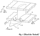
- FIG. 1 shows a schematic view of a plurality of guide vane platforms 10 according to FIG the state of the art.
- a scoop element 12 which comes from the combustion chamber Deflects hot gas flow 20.
- An area 14 is formed in front of each guide vane 12 maximum pressure directly in front of the front edge of the bucket.
- the dynamic pressure before The leading edge is higher than the mean pressure 16 in the space between the last combustion chamber segment and the guide vane platform 10.
- the hot gas flows radially inwards on the lower platforms into the intermediate space (reference symbol 18) and along the circumference of the combustion chamber from the blade path.
- the hot gas flows radially accordingly on the upper platforms outside in the space.
- the adjacent vane carrier is often made of low-alloy Steel and is much less heat-resistant than that directly to the hot gas flow exposed components.
- Figure 2 shows a side view of an embodiment of an inventive Platform cooling for an upper platform 30.
- the viewing direction and orientation The platform for the correct definition of the angles occurring is in FIG. 1 shown on the left.
- the line of sight (“view (Fig. 2)") forms the surface normal onto the platform ("N") and the hot gas flow direction (“HG”) as in FIG. 1 shown a legal system.
- Figure 2 shows an upper platform 30, a combustion chamber segment 40, a guide blade carrier 52 and a blade element 12.
- the upper platform 30 is separated from combustion chamber segment 40 by a gap 36. Both the combustion chamber segment 40 and the platform 30 are included Hooks 46 and 38 hooked into the same guide vane carrier 52.
- the side of the combustion chamber segment 40 facing the gap 36 forms with the Horizontal an angle ⁇ , so that the axis of the gap 36 also an angle ⁇ with the horizontal.
- the opposite surface of the Platform 30 is designed so that it forms an angle ⁇ with the horizontal (Reference numeral 34).
- the angles ⁇ and ⁇ are chosen so that the segment cooling holes are slightly more inclined to the horizontal than the surface 34, but that the cooling air flow of the segment cooling holes 42 is approximately tangential flows along the surface 34. In the present exemplary embodiment, ⁇ is approximately 25 °, and ⁇ chosen to be about 30 °.
- the cooling air flow of the segment cooling holes 42 therefore flows at a flat angle along the surface 34 and reaches the area of platform 30 exposed to hot gas flow 20.
- a number of platform cooling holes 32 are made in platform 30, which connect the cooling chamber 39 to the gap 36, each of the axes the platform cooling holes form an angle ⁇ with the horizontal.
- a concave recess 48 is provided, which redirects the cooling air flow, and in the direction of that of the hot gas flow exposed volume conducts.
- the angles ⁇ , ⁇ , ⁇ are chosen so that ⁇ lies between ⁇ and ⁇ .
- ⁇ is approximately 45 °, ⁇ approximately 30 °, and ⁇ approximately 20 °. This choice of the relationships between the angles ⁇ and ⁇ achieves that the gap width is not significantly dependent on geometric tolerances and / or displacements influenced by thermal expansions (reference numeral 50) becomes.
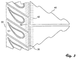
- the location of the axes of the segment cooling holes 42 and the platform cooling holes 32 along the circumference of the annular combustion chamber is in the bottom view of Fig. 3 shown.
- the holes are alternating along the circumference and against each other staggered.
- they are also radially offset from each other.
- Both the platform cooling holes 32 and the segment cooling holes 42 can be designed as cylindrical bores or as funnel bores.
- An advantage of using funnel bores is the wider coverage of the cooling film and in the lower exit velocity of the cooling jet from the holes. The low exit speed results in a lot low aerodynamic losses.
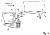
- Figure 4 shows a side view of an embodiment of an inventive Platform cooling for a lower platform 60.
- the viewing direction and orientation The platform for the correct definition of the angles occurring is in FIG. 1 shown on the right.
- the direction of view (“view (Fig. 4)"), the surface normal (“N”) and the hot gas flow direction (“HG”) as shown in Fig. 1 is a legal system.
- view (Fig. 4) The direction of view
- N the surface normal
- HG hot gas flow direction
- anti-clockwise angles become positive, Clockwise angle measured negatively.
- the lower platform 60 is separated from a combustion chamber segment by a gap 66 70 separated.
- Platform 60 and combustion chamber segment 70 are on a common one Carrier 82 attached.
- a series of segment cooling bores 72 connect at an angle ⁇ the cooling chamber 74 with the gap 66, and a row platform cooling bores 62 connect the cooling chamber 69 to the gap 66 at an angle ⁇ .
- the surface of the platform 60 closes in the area of the Make an angle ⁇ with the horizontal (reference numeral 64).
- ⁇ is selected at approximately 30 ° and ⁇ at approximately 25 °.
- the angle ⁇ in this exemplary embodiment is approximately -15 ° chosen.
- the platform cooling holes 62 thus also blow cooling air in the direction to the open end of the gap 66.
- This cooling air flow is through the lip 79 deflected and leaves the gap essentially parallel to the hot gas flow 20.
- the lip 79 stretches over the opening of the gap 66 and decreases hence its effective width. This leads to a further reduction in the hot gas break-in into the gap 66.
- the lip 79 is as far as possible over the gap 66 drawn, and, in order to avoid burning, by the cooling air flow of the Segment cooling bore 72 cooled.
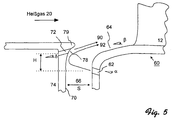
- FIG. 5 An advantageous arrangement of the bores and the lip of a further exemplary embodiment is shown in detail in FIG. 5.
- the inside of the combustion chamber segment 70 facing the gap 66 is configured together with the lip 79 in such a way that a concave curvature 78 of the inside is created.
- the cooling air flow 90 of the platform cooling bore 62 is deflected such that it leaves the gap 66 approximately parallel to the hot gas flow 20.
- the distance H from the segment cooling bore 72 and platform cooling bore 62 is selected so that the cooling air flows 90 and 92 do not intersect. This is the case if H is chosen such that, for a gap width S, the angle ⁇ is smaller than arctan (H / S) is.
Landscapes
- Engineering & Computer Science (AREA)
- Mechanical Engineering (AREA)
- General Engineering & Computer Science (AREA)
- Turbine Rotor Nozzle Sealing (AREA)
Priority Applications (3)
| Application Number | Priority Date | Filing Date | Title |
|---|---|---|---|
| EP97810660A EP0902164B1 (fr) | 1997-09-15 | 1997-09-15 | Refroidissement de la platte-forme dans les turbines à gas |
| DE59709701T DE59709701D1 (de) | 1997-09-15 | 1997-09-15 | Plattformkühlung für Gasturbinen |
| US09/152,516 US6082961A (en) | 1997-09-15 | 1998-09-14 | Platform cooling for gas turbines |
Applications Claiming Priority (1)
| Application Number | Priority Date | Filing Date | Title |
|---|---|---|---|
| EP97810660A EP0902164B1 (fr) | 1997-09-15 | 1997-09-15 | Refroidissement de la platte-forme dans les turbines à gas |
Publications (2)
| Publication Number | Publication Date |
|---|---|
| EP0902164A1 true EP0902164A1 (fr) | 1999-03-17 |
| EP0902164B1 EP0902164B1 (fr) | 2003-04-02 |
Family
ID=8230378
Family Applications (1)
| Application Number | Title | Priority Date | Filing Date |
|---|---|---|---|
| EP97810660A Expired - Lifetime EP0902164B1 (fr) | 1997-09-15 | 1997-09-15 | Refroidissement de la platte-forme dans les turbines à gas |
Country Status (3)
| Country | Link |
|---|---|
| US (1) | US6082961A (fr) |
| EP (1) | EP0902164B1 (fr) |
| DE (1) | DE59709701D1 (fr) |
Cited By (9)
| Publication number | Priority date | Publication date | Assignee | Title |
|---|---|---|---|---|
| EP1607580A2 (fr) | 2004-06-15 | 2005-12-21 | Rolls-Royce Deutschland Ltd & Co KG | Refroidissement d'une plate-forme des aubes dans une turbine à gaz |
| EP1749967A3 (fr) * | 2005-08-02 | 2008-07-30 | Rolls-Royce plc | Dispositif de refroidissement de turbine à gaz |
| EP1985806A1 (fr) * | 2007-04-27 | 2008-10-29 | Siemens Aktiengesellschaft | Refroidissement d'anneau de renforcement d'une aube fixe de turbine |
| WO2009019282A2 (fr) | 2007-08-06 | 2009-02-12 | Alstom Technology Ltd | Installation de turbine à gaz |
| WO2009083456A3 (fr) * | 2007-12-29 | 2009-09-17 | Alstom Technology Ltd | Turbine à gaz |
| EP2754858A1 (fr) | 2013-01-14 | 2014-07-16 | Alstom Technology Ltd | Dispositif pour étanchéifier une cavité ouverte contre un entraînement gazeux chaud |
| EP2871323A1 (fr) * | 2013-11-06 | 2015-05-13 | Mitsubishi Hitachi Power Systems, Ltd. | Refroidissement de paroi d'extrémité d'une tuyère de guidage d'une turbine à gaz |
| DE102014221783A1 (de) * | 2014-10-27 | 2016-04-28 | Siemens Aktiengesellschaft | Heißgaskanal |
| DE102019211418A1 (de) * | 2019-07-31 | 2021-02-04 | Siemens Aktiengesellschaft | Verfahren zur Modernisierung einer Gasturbinenanlage sowie Gasturbinenanlage |
Families Citing this family (39)
| Publication number | Priority date | Publication date | Assignee | Title |
|---|---|---|---|---|
| DE59808481D1 (de) * | 1998-11-09 | 2003-06-26 | Alstom Switzerland Ltd | Gekühlte Komponenten mit konischen Kühlungskanälen |
| EP1207268B1 (fr) | 2000-11-16 | 2005-02-09 | Siemens Aktiengesellschaft | Aube de turbine à gaz et procédé de fabrication d'une aube de turbine à gaz |
| US6896483B2 (en) | 2001-07-02 | 2005-05-24 | Allison Advanced Development Company | Blade track assembly |
| US6945749B2 (en) * | 2003-09-12 | 2005-09-20 | Siemens Westinghouse Power Corporation | Turbine blade platform cooling system |
| US7004720B2 (en) * | 2003-12-17 | 2006-02-28 | Pratt & Whitney Canada Corp. | Cooled turbine vane platform |
| US7097417B2 (en) * | 2004-02-09 | 2006-08-29 | Siemens Westinghouse Power Corporation | Cooling system for an airfoil vane |
| US7097418B2 (en) * | 2004-06-18 | 2006-08-29 | Pratt & Whitney Canada Corp. | Double impingement vane platform cooling |
| US7186089B2 (en) * | 2004-11-04 | 2007-03-06 | Siemens Power Generation, Inc. | Cooling system for a platform of a turbine blade |
| US7179049B2 (en) * | 2004-12-10 | 2007-02-20 | Pratt & Whitney Canada Corp. | Gas turbine gas path contour |
| US7452184B2 (en) * | 2004-12-13 | 2008-11-18 | Pratt & Whitney Canada Corp. | Airfoil platform impingement cooling |
| EP1741877A1 (fr) * | 2005-07-04 | 2007-01-10 | Siemens Aktiengesellschaft | Écran thermique et aube de distributeur pour une turbine à gaz |
| US20070134087A1 (en) * | 2005-12-08 | 2007-06-14 | General Electric Company | Methods and apparatus for assembling turbine engines |
| US7857580B1 (en) | 2006-09-15 | 2010-12-28 | Florida Turbine Technologies, Inc. | Turbine vane with end-wall leading edge cooling |
| GB2442967B (en) * | 2006-10-21 | 2011-02-16 | Rolls Royce Plc | An engine arrangement |
| US7785067B2 (en) * | 2006-11-30 | 2010-08-31 | General Electric Company | Method and system to facilitate cooling turbine engines |
| US7690885B2 (en) * | 2006-11-30 | 2010-04-06 | General Electric Company | Methods and system for shielding cooling air to facilitate cooling integral turbine nozzle and shroud assemblies |
| US7862291B2 (en) * | 2007-02-08 | 2011-01-04 | United Technologies Corporation | Gas turbine engine component cooling scheme |
| US20090169361A1 (en) * | 2007-12-29 | 2009-07-02 | Michael Scott Cole | Cooled turbine nozzle segment |
| US20090165275A1 (en) * | 2007-12-29 | 2009-07-02 | Michael Scott Cole | Method for repairing a cooled turbine nozzle segment |
| US8057178B2 (en) * | 2008-09-04 | 2011-11-15 | General Electric Company | Turbine bucket for a turbomachine and method of reducing bow wave effects at a turbine bucket |
| US8070422B1 (en) * | 2008-12-16 | 2011-12-06 | Florida Turbine Technologies, Inc. | Turbine stator vane and rotor blade arrangement |
| GB0905548D0 (en) * | 2009-04-01 | 2009-05-13 | Rolls Royce Plc | A rotor arrangement |
| CH703105A1 (de) * | 2010-05-05 | 2011-11-15 | Alstom Technology Ltd | Gasturbine mit einer sekundärbrennkammer. |
| EP2423435A1 (fr) * | 2010-08-30 | 2012-02-29 | Siemens Aktiengesellschaft | Aube de turbomachine |
| RU2543101C2 (ru) * | 2010-11-29 | 2015-02-27 | Альстом Текнолоджи Лтд | Осевая газовая турбина |
| US8979481B2 (en) * | 2011-10-26 | 2015-03-17 | General Electric Company | Turbine bucket angel wing features for forward cavity flow control and related method |
| US8870525B2 (en) | 2011-11-04 | 2014-10-28 | General Electric Company | Bucket assembly for turbine system |
| US8840370B2 (en) | 2011-11-04 | 2014-09-23 | General Electric Company | Bucket assembly for turbine system |
| US8845289B2 (en) | 2011-11-04 | 2014-09-30 | General Electric Company | Bucket assembly for turbine system |
| EP2634373A1 (fr) * | 2012-02-28 | 2013-09-04 | Siemens Aktiengesellschaft | Agencement pour turbomachine |
| US20140116660A1 (en) * | 2012-10-31 | 2014-05-01 | General Electric Company | Components with asymmetric cooling channels and methods of manufacture |
| US9752447B2 (en) * | 2014-04-04 | 2017-09-05 | United Technologies Corporation | Angled rail holes |
| EP3115556B1 (fr) * | 2015-07-10 | 2020-09-23 | Ansaldo Energia Switzerland AG | Turbine à gaz |
| US10458266B2 (en) * | 2017-04-18 | 2019-10-29 | United Technologies Corporation | Forward facing tangential onboard injectors for gas turbine engines |
| US11118474B2 (en) | 2017-10-09 | 2021-09-14 | Raytheon Technologies Corporation | Vane cooling structures |
| JP7451108B2 (ja) * | 2019-08-16 | 2024-03-18 | 三菱重工業株式会社 | 静翼、及びこれを備えているガスタービン |
| WO2021246999A1 (fr) * | 2020-06-01 | 2021-12-09 | Siemens Aktiengesellschaft | Segment de bague pour turbine à gaz |
| EP4019742B1 (fr) * | 2020-12-23 | 2024-10-23 | ANSALDO ENERGIA S.p.A. | Ensemble d'étanchéité pour un jeu d'aubes d'un moteur à turbine à gaz et moteur à turbine à gaz comprenant un tel ensemble d'étanchéité |
| CN118414474A (zh) | 2022-01-06 | 2024-07-30 | 三菱重工业株式会社 | 涡轮静叶片及嵌合结构以及燃气涡轮 |
Citations (3)
| Publication number | Priority date | Publication date | Assignee | Title |
|---|---|---|---|---|
| EP0037897A1 (fr) * | 1980-04-15 | 1981-10-21 | M.A.N. MASCHINENFABRIK AUGSBURG-NÜRNBERG Aktiengesellschaft | Dispositif de refroidissement interne d'une turbine à gaz |
| GB2119027A (en) * | 1982-04-24 | 1983-11-09 | Rolls Royce | Turbine assembly for a gas turbine engine |
| GB2122690A (en) * | 1982-07-01 | 1984-01-18 | Skoda Kp | Steam turbine bleeding slot |
Family Cites Families (4)
| Publication number | Priority date | Publication date | Assignee | Title |
|---|---|---|---|---|
| US4126405A (en) * | 1976-12-16 | 1978-11-21 | General Electric Company | Turbine nozzle |
| US4821522A (en) * | 1987-07-02 | 1989-04-18 | United Technologies Corporation | Sealing and cooling arrangement for combustor vane interface |
| GB9305010D0 (en) * | 1993-03-11 | 1993-04-28 | Rolls Royce Plc | A cooled turbine nozzle assembly and a method of calculating the diameters of cooling holes for use in such an assembly |
| GB9305012D0 (en) * | 1993-03-11 | 1993-04-28 | Rolls Royce Plc | Sealing structures for gas turbine engines |
-
1997
- 1997-09-15 DE DE59709701T patent/DE59709701D1/de not_active Expired - Lifetime
- 1997-09-15 EP EP97810660A patent/EP0902164B1/fr not_active Expired - Lifetime
-
1998
- 1998-09-14 US US09/152,516 patent/US6082961A/en not_active Expired - Lifetime
Patent Citations (3)
| Publication number | Priority date | Publication date | Assignee | Title |
|---|---|---|---|---|
| EP0037897A1 (fr) * | 1980-04-15 | 1981-10-21 | M.A.N. MASCHINENFABRIK AUGSBURG-NÜRNBERG Aktiengesellschaft | Dispositif de refroidissement interne d'une turbine à gaz |
| GB2119027A (en) * | 1982-04-24 | 1983-11-09 | Rolls Royce | Turbine assembly for a gas turbine engine |
| GB2122690A (en) * | 1982-07-01 | 1984-01-18 | Skoda Kp | Steam turbine bleeding slot |
Cited By (21)
| Publication number | Priority date | Publication date | Assignee | Title |
|---|---|---|---|---|
| US7637716B2 (en) | 2004-06-15 | 2009-12-29 | Rolls-Royce Deutschland Ltd & Co Kg | Platform cooling arrangement for the nozzle guide vane stator of a gas turbine |
| EP1607580A3 (fr) * | 2004-06-15 | 2008-10-01 | Rolls-Royce Deutschland Ltd & Co KG | Refroidissement d'une plate-forme des aubes dans une turbine à gaz |
| EP1607580A2 (fr) | 2004-06-15 | 2005-12-21 | Rolls-Royce Deutschland Ltd & Co KG | Refroidissement d'une plate-forme des aubes dans une turbine à gaz |
| EP1749967A3 (fr) * | 2005-08-02 | 2008-07-30 | Rolls-Royce plc | Dispositif de refroidissement de turbine à gaz |
| US7648333B2 (en) | 2005-08-02 | 2010-01-19 | Rolls-Royce Plc | Cooling arrangement |
| EP1985806A1 (fr) * | 2007-04-27 | 2008-10-29 | Siemens Aktiengesellschaft | Refroidissement d'anneau de renforcement d'une aube fixe de turbine |
| WO2008132082A1 (fr) * | 2007-04-27 | 2008-11-06 | Siemens Aktiengesellschaft | Refroidissement de plate-forme d'aube de turbine |
| US8672612B2 (en) | 2007-04-27 | 2014-03-18 | Siemens Aktiengesellschaft | Platform cooling of turbine vane |
| US8132417B2 (en) | 2007-08-06 | 2012-03-13 | Alstom Technology Ltd. | Cooling of a gas turbine engine downstream of combustion chamber |
| WO2009019282A3 (fr) * | 2007-08-06 | 2009-05-07 | Alstom Technology Ltd | Installation de turbine à gaz |
| WO2009019282A2 (fr) | 2007-08-06 | 2009-02-12 | Alstom Technology Ltd | Installation de turbine à gaz |
| WO2009083456A3 (fr) * | 2007-12-29 | 2009-09-17 | Alstom Technology Ltd | Turbine à gaz |
| US8783044B2 (en) | 2007-12-29 | 2014-07-22 | Alstom Technology Ltd | Turbine stator nozzle cooling structure |
| EP2754858A1 (fr) | 2013-01-14 | 2014-07-16 | Alstom Technology Ltd | Dispositif pour étanchéifier une cavité ouverte contre un entraînement gazeux chaud |
| US9074488B2 (en) | 2013-01-14 | 2015-07-07 | Alstom Technology Ltd | Arrangement for sealing an open cavity against hot gas entrainment |
| EP2871323A1 (fr) * | 2013-11-06 | 2015-05-13 | Mitsubishi Hitachi Power Systems, Ltd. | Refroidissement de paroi d'extrémité d'une tuyère de guidage d'une turbine à gaz |
| US9790799B2 (en) | 2013-11-06 | 2017-10-17 | Mitsubishi Hitachi Power Systems, Ltd. | Gas turbine airfoil |
| DE102014221783A1 (de) * | 2014-10-27 | 2016-04-28 | Siemens Aktiengesellschaft | Heißgaskanal |
| DE102019211418A1 (de) * | 2019-07-31 | 2021-02-04 | Siemens Aktiengesellschaft | Verfahren zur Modernisierung einer Gasturbinenanlage sowie Gasturbinenanlage |
| WO2021018495A1 (fr) * | 2019-07-31 | 2021-02-04 | Siemens Energy Global GmbH & Co. KG | Procédé d'amélioration d'une turbine à gaz et turbine à gaz |
| US11879346B2 (en) | 2019-07-31 | 2024-01-23 | Siemens Energy Global GmbH & Co. KG | Method for upgrading a gas turbine and gas turbine |
Also Published As
| Publication number | Publication date |
|---|---|
| US6082961A (en) | 2000-07-04 |
| DE59709701D1 (de) | 2003-05-08 |
| EP0902164B1 (fr) | 2003-04-02 |
Similar Documents
| Publication | Publication Date | Title |
|---|---|---|
| EP0902164B1 (fr) | Refroidissement de la platte-forme dans les turbines à gas | |
| DE60018817T2 (de) | Gekühlte Gasturbinenschaufel | |
| DE1946535C3 (de) | Bauteil für ein Gasturbinentriebwerk | |
| DE69831109T2 (de) | Kühlluftzufuhrsystem für die Schaufeln einer Gasturbine | |
| EP1320661B1 (fr) | Aube de turbine a gaz | |
| DE69926574T2 (de) | Turbinenleitgitter mit einem Kühlluftleitsystem | |
| DE10303088B4 (de) | Abgasgehäuse einer Wärmekraftmaschine | |
| EP0528138B1 (fr) | Anneau d'aube de turbine axiale | |
| EP0536575B1 (fr) | Bande de recouvrement pour roue de turbine axiale | |
| DE69420582T2 (de) | Kühlung einer schaufel in nähe der staulinie | |
| EP3762587B1 (fr) | Pale d'aube pour une aube de turbine | |
| EP1740797B1 (fr) | Turbine a gaz | |
| EP2179143B1 (fr) | Refroidissement de fente entre une paroi de chambre de combustion et une paroi de turbine d'une installation de turbine à gaz | |
| DE19809008C2 (de) | Gasturbinenschaufel | |
| EP0799973B1 (fr) | Contour de paroi pour une turbomachine axiale | |
| DE60017396T2 (de) | Vorrichtung zur reduzierung der kühlung für einen turbineneinlasskanal | |
| DE3711024A1 (de) | Gekuehlte schaufel fuer ein gasturbinentriebwerk | |
| DE10344843B4 (de) | Integrierte Rotations-Messerkanten-Injektionsanordnung | |
| CH702101B1 (de) | Turbinenschaufel mit Winglet. | |
| DE1601557A1 (de) | Stroemungsmittelgekuehlte Statoranordnung | |
| DE2935235A1 (de) | Gasverdichter | |
| EP0491966B1 (fr) | Dispositif de support d'une turbomachine thermique | |
| DE102008055522A1 (de) | Divergente Turbinendüse | |
| EP0313826A1 (fr) | Turbine à gaz avec flux axial | |
| DE3779460T2 (de) | Abgasturbine. |
Legal Events
| Date | Code | Title | Description |
|---|---|---|---|
| PUAI | Public reference made under article 153(3) epc to a published international application that has entered the european phase |
Free format text: ORIGINAL CODE: 0009012 |
|
| AK | Designated contracting states |
Kind code of ref document: A1 Designated state(s): DE |
|
| AX | Request for extension of the european patent |
Free format text: AL;LT;LV;RO;SI |
|
| 17P | Request for examination filed |
Effective date: 19990903 |
|
| AKX | Designation fees paid |
Free format text: DE |
|
| RAP1 | Party data changed (applicant data changed or rights of an application transferred) |
Owner name: ALSTOM |
|
| 17Q | First examination report despatched |
Effective date: 20011221 |
|
| GRAH | Despatch of communication of intention to grant a patent |
Free format text: ORIGINAL CODE: EPIDOS IGRA |
|
| RAP1 | Party data changed (applicant data changed or rights of an application transferred) |
Owner name: ALSTOM (SWITZERLAND) LTD |
|
| GRAH | Despatch of communication of intention to grant a patent |
Free format text: ORIGINAL CODE: EPIDOS IGRA |
|
| GRAA | (expected) grant |
Free format text: ORIGINAL CODE: 0009210 |
|
| AK | Designated contracting states |
Designated state(s): DE |
|
| REF | Corresponds to: |
Ref document number: 59709701 Country of ref document: DE Date of ref document: 20030508 Kind code of ref document: P |
|
| PLBE | No opposition filed within time limit |
Free format text: ORIGINAL CODE: 0009261 |
|
| STAA | Information on the status of an ep patent application or granted ep patent |
Free format text: STATUS: NO OPPOSITION FILED WITHIN TIME LIMIT |
|
| 26N | No opposition filed |
Effective date: 20040105 |
|
| REG | Reference to a national code |
Ref country code: DE Ref legal event code: R082 Ref document number: 59709701 Country of ref document: DE Representative=s name: UWE ROESLER, DE |
|
| REG | Reference to a national code |
Ref country code: DE Ref legal event code: R082 Ref document number: 59709701 Country of ref document: DE Representative=s name: ROESLER, UWE, DIPL.-PHYS.UNIV., DE Effective date: 20120713 Ref country code: DE Ref legal event code: R081 Ref document number: 59709701 Country of ref document: DE Owner name: GENERAL ELECTRIC TECHNOLOGY GMBH, CH Free format text: FORMER OWNER: ALSTOM (SWITZERLAND) LTD., BADEN, CH Effective date: 20120713 Ref country code: DE Ref legal event code: R081 Ref document number: 59709701 Country of ref document: DE Owner name: ALSTOM TECHNOLOGY LTD., CH Free format text: FORMER OWNER: ALSTOM (SWITZERLAND) LTD., BADEN, CH Effective date: 20120713 |
|
| REG | Reference to a national code |
Ref country code: DE Ref legal event code: R082 Ref document number: 59709701 Country of ref document: DE Representative=s name: ROESLER, UWE, DIPL.-PHYS.UNIV., DE Ref country code: DE Ref legal event code: R081 Ref document number: 59709701 Country of ref document: DE Owner name: GENERAL ELECTRIC TECHNOLOGY GMBH, CH Free format text: FORMER OWNER: ALSTOM TECHNOLOGY LTD., BADEN, CH |
|
| PGFP | Annual fee paid to national office [announced via postgrant information from national office to epo] |
Ref country code: DE Payment date: 20160921 Year of fee payment: 20 |
|
| REG | Reference to a national code |
Ref country code: DE Ref legal event code: R071 Ref document number: 59709701 Country of ref document: DE |