EP0902167A1 - Kühlvorrichtung für Gasturbinenkomponenten - Google Patents
Kühlvorrichtung für Gasturbinenkomponenten Download PDFInfo
- Publication number
- EP0902167A1 EP0902167A1 EP97810659A EP97810659A EP0902167A1 EP 0902167 A1 EP0902167 A1 EP 0902167A1 EP 97810659 A EP97810659 A EP 97810659A EP 97810659 A EP97810659 A EP 97810659A EP 0902167 A1 EP0902167 A1 EP 0902167A1
- Authority
- EP
- European Patent Office
- Prior art keywords
- segment
- gap
- edge
- hot gas
- arrangement according
- Prior art date
- Legal status (The legal status is an assumption and is not a legal conclusion. Google has not performed a legal analysis and makes no representation as to the accuracy of the status listed.)
- Granted
Links
Images




Classifications
-
- F—MECHANICAL ENGINEERING; LIGHTING; HEATING; WEAPONS; BLASTING
- F01—MACHINES OR ENGINES IN GENERAL; ENGINE PLANTS IN GENERAL; STEAM ENGINES
- F01D—NON-POSITIVE DISPLACEMENT MACHINES OR ENGINES, e.g. STEAM TURBINES
- F01D25/00—Component parts, details, or accessories, not provided for in, or of interest apart from, other groups
- F01D25/08—Cooling; Heating; Heat-insulation
- F01D25/12—Cooling
-
- F—MECHANICAL ENGINEERING; LIGHTING; HEATING; WEAPONS; BLASTING
- F01—MACHINES OR ENGINES IN GENERAL; ENGINE PLANTS IN GENERAL; STEAM ENGINES
- F01D—NON-POSITIVE DISPLACEMENT MACHINES OR ENGINES, e.g. STEAM TURBINES
- F01D11/00—Preventing or minimising internal leakage of working-fluid, e.g. between stages
- F01D11/005—Sealing means between non relatively rotating elements
- F01D11/006—Sealing the gap between rotor blades or blades and rotor
-
- F—MECHANICAL ENGINEERING; LIGHTING; HEATING; WEAPONS; BLASTING
- F01—MACHINES OR ENGINES IN GENERAL; ENGINE PLANTS IN GENERAL; STEAM ENGINES
- F01D—NON-POSITIVE DISPLACEMENT MACHINES OR ENGINES, e.g. STEAM TURBINES
- F01D11/00—Preventing or minimising internal leakage of working-fluid, e.g. between stages
- F01D11/02—Preventing or minimising internal leakage of working-fluid, e.g. between stages by non-contact sealings, e.g. of labyrinth type
- F01D11/04—Preventing or minimising internal leakage of working-fluid, e.g. between stages by non-contact sealings, e.g. of labyrinth type using sealing fluid, e.g. steam
-
- F—MECHANICAL ENGINEERING; LIGHTING; HEATING; WEAPONS; BLASTING
- F01—MACHINES OR ENGINES IN GENERAL; ENGINE PLANTS IN GENERAL; STEAM ENGINES
- F01D—NON-POSITIVE DISPLACEMENT MACHINES OR ENGINES, e.g. STEAM TURBINES
- F01D5/00—Blades; Blade-carrying members; Heating, heat-insulating, cooling or antivibration means on the blades or the members
- F01D5/02—Blade-carrying members, e.g. rotors
- F01D5/08—Heating, heat-insulating or cooling means
-
- F—MECHANICAL ENGINEERING; LIGHTING; HEATING; WEAPONS; BLASTING
- F01—MACHINES OR ENGINES IN GENERAL; ENGINE PLANTS IN GENERAL; STEAM ENGINES
- F01D—NON-POSITIVE DISPLACEMENT MACHINES OR ENGINES, e.g. STEAM TURBINES
- F01D5/00—Blades; Blade-carrying members; Heating, heat-insulating, cooling or antivibration means on the blades or the members
- F01D5/12—Blades
- F01D5/14—Form or construction
- F01D5/141—Shape, i.e. outer, aerodynamic form
- F01D5/142—Shape, i.e. outer, aerodynamic form of the blades of successive rotor or stator blade-rows
- F01D5/143—Contour of the outer or inner working fluid flow path wall, i.e. shroud or hub contour
-
- F—MECHANICAL ENGINEERING; LIGHTING; HEATING; WEAPONS; BLASTING
- F01—MACHINES OR ENGINES IN GENERAL; ENGINE PLANTS IN GENERAL; STEAM ENGINES
- F01D—NON-POSITIVE DISPLACEMENT MACHINES OR ENGINES, e.g. STEAM TURBINES
- F01D5/00—Blades; Blade-carrying members; Heating, heat-insulating, cooling or antivibration means on the blades or the members
- F01D5/12—Blades
- F01D5/14—Form or construction
- F01D5/18—Hollow blades, i.e. blades with cooling or heating channels or cavities; Heating, heat-insulating or cooling means on blades
- F01D5/187—Convection cooling
-
- F—MECHANICAL ENGINEERING; LIGHTING; HEATING; WEAPONS; BLASTING
- F05—INDEXING SCHEMES RELATING TO ENGINES OR PUMPS IN VARIOUS SUBCLASSES OF CLASSES F01-F04
- F05D—INDEXING SCHEME FOR ASPECTS RELATING TO NON-POSITIVE-DISPLACEMENT MACHINES OR ENGINES, GAS-TURBINES OR JET-PROPULSION PLANTS
- F05D2250/00—Geometry
- F05D2250/10—Two-dimensional
- F05D2250/14—Two-dimensional elliptical
-
- F—MECHANICAL ENGINEERING; LIGHTING; HEATING; WEAPONS; BLASTING
- F05—INDEXING SCHEMES RELATING TO ENGINES OR PUMPS IN VARIOUS SUBCLASSES OF CLASSES F01-F04
- F05D—INDEXING SCHEME FOR ASPECTS RELATING TO NON-POSITIVE-DISPLACEMENT MACHINES OR ENGINES, GAS-TURBINES OR JET-PROPULSION PLANTS
- F05D2250/00—Geometry
- F05D2250/10—Two-dimensional
- F05D2250/16—Two-dimensional parabolic
-
- F—MECHANICAL ENGINEERING; LIGHTING; HEATING; WEAPONS; BLASTING
- F05—INDEXING SCHEMES RELATING TO ENGINES OR PUMPS IN VARIOUS SUBCLASSES OF CLASSES F01-F04
- F05D—INDEXING SCHEME FOR ASPECTS RELATING TO NON-POSITIVE-DISPLACEMENT MACHINES OR ENGINES, GAS-TURBINES OR JET-PROPULSION PLANTS
- F05D2250/00—Geometry
- F05D2250/10—Two-dimensional
- F05D2250/19—Two-dimensional machined; miscellaneous
- F05D2250/192—Two-dimensional machined; miscellaneous bevelled
-
- F—MECHANICAL ENGINEERING; LIGHTING; HEATING; WEAPONS; BLASTING
- F05—INDEXING SCHEMES RELATING TO ENGINES OR PUMPS IN VARIOUS SUBCLASSES OF CLASSES F01-F04
- F05D—INDEXING SCHEME FOR ASPECTS RELATING TO NON-POSITIVE-DISPLACEMENT MACHINES OR ENGINES, GAS-TURBINES OR JET-PROPULSION PLANTS
- F05D2250/00—Geometry
- F05D2250/20—Three-dimensional
- F05D2250/23—Three-dimensional prismatic
- F05D2250/231—Three-dimensional prismatic cylindrical
-
- F—MECHANICAL ENGINEERING; LIGHTING; HEATING; WEAPONS; BLASTING
- F05—INDEXING SCHEMES RELATING TO ENGINES OR PUMPS IN VARIOUS SUBCLASSES OF CLASSES F01-F04
- F05D—INDEXING SCHEME FOR ASPECTS RELATING TO NON-POSITIVE-DISPLACEMENT MACHINES OR ENGINES, GAS-TURBINES OR JET-PROPULSION PLANTS
- F05D2250/00—Geometry
- F05D2250/20—Three-dimensional
- F05D2250/29—Three-dimensional machined; miscellaneous
- F05D2250/292—Three-dimensional machined; miscellaneous tapered
-
- F—MECHANICAL ENGINEERING; LIGHTING; HEATING; WEAPONS; BLASTING
- F05—INDEXING SCHEMES RELATING TO ENGINES OR PUMPS IN VARIOUS SUBCLASSES OF CLASSES F01-F04
- F05D—INDEXING SCHEME FOR ASPECTS RELATING TO NON-POSITIVE-DISPLACEMENT MACHINES OR ENGINES, GAS-TURBINES OR JET-PROPULSION PLANTS
- F05D2250/00—Geometry
- F05D2250/30—Arrangement of components
- F05D2250/31—Arrangement of components according to the direction of their main axis or their axis of rotation
- F05D2250/312—Arrangement of components according to the direction of their main axis or their axis of rotation the axes being parallel to each other
-
- F—MECHANICAL ENGINEERING; LIGHTING; HEATING; WEAPONS; BLASTING
- F05—INDEXING SCHEMES RELATING TO ENGINES OR PUMPS IN VARIOUS SUBCLASSES OF CLASSES F01-F04
- F05D—INDEXING SCHEME FOR ASPECTS RELATING TO NON-POSITIVE-DISPLACEMENT MACHINES OR ENGINES, GAS-TURBINES OR JET-PROPULSION PLANTS
- F05D2250/00—Geometry
- F05D2250/30—Arrangement of components
- F05D2250/31—Arrangement of components according to the direction of their main axis or their axis of rotation
- F05D2250/314—Arrangement of components according to the direction of their main axis or their axis of rotation the axes being inclined in relation to each other
-
- F—MECHANICAL ENGINEERING; LIGHTING; HEATING; WEAPONS; BLASTING
- F05—INDEXING SCHEMES RELATING TO ENGINES OR PUMPS IN VARIOUS SUBCLASSES OF CLASSES F01-F04
- F05D—INDEXING SCHEME FOR ASPECTS RELATING TO NON-POSITIVE-DISPLACEMENT MACHINES OR ENGINES, GAS-TURBINES OR JET-PROPULSION PLANTS
- F05D2250/00—Geometry
- F05D2250/30—Arrangement of components
- F05D2250/32—Arrangement of components according to their shape
- F05D2250/322—Arrangement of components according to their shape tangential
-
- F—MECHANICAL ENGINEERING; LIGHTING; HEATING; WEAPONS; BLASTING
- F05—INDEXING SCHEMES RELATING TO ENGINES OR PUMPS IN VARIOUS SUBCLASSES OF CLASSES F01-F04
- F05D—INDEXING SCHEME FOR ASPECTS RELATING TO NON-POSITIVE-DISPLACEMENT MACHINES OR ENGINES, GAS-TURBINES OR JET-PROPULSION PLANTS
- F05D2260/00—Function
- F05D2260/20—Heat transfer, e.g. cooling
- F05D2260/202—Heat transfer, e.g. cooling by film cooling
-
- Y—GENERAL TAGGING OF NEW TECHNOLOGICAL DEVELOPMENTS; GENERAL TAGGING OF CROSS-SECTIONAL TECHNOLOGIES SPANNING OVER SEVERAL SECTIONS OF THE IPC; TECHNICAL SUBJECTS COVERED BY FORMER USPC CROSS-REFERENCE ART COLLECTIONS [XRACs] AND DIGESTS
- Y02—TECHNOLOGIES OR APPLICATIONS FOR MITIGATION OR ADAPTATION AGAINST CLIMATE CHANGE
- Y02T—CLIMATE CHANGE MITIGATION TECHNOLOGIES RELATED TO TRANSPORTATION
- Y02T50/00—Aeronautics or air transport
- Y02T50/60—Efficient propulsion technologies, e.g. for aircraft
Definitions
- the invention relates to a segment arrangement for platforms, in particular in a Gas turbine with a hot gas stream flowing along its surface, side by side arranged segments, each separated by a gap wherein in at least a partial area of the gap the hot gas flow is one Velocity component perpendicular to the direction of the gap, from a first Has segment to a second segment.
- Critical components in turbines represent, among other things, heat shields, combustion chamber segments and combustion chamber plates, moving and guide blades, inner and outer shrouds the rotor and guide vanes, as well as the rotor and guide vane platforms represents.
- the invention is based, with regard to high temperatures, the task critical components, in particular components composed of segments, so interpret that the thermal load on these components with the simplest possible Means is effectively reduced.
- This object is achieved in a first aspect in that the edge of each segment impinged on the hot gas flow from the impinging one Hot gas flow is reset.
- the hot gas stream flows on the surface of the juxtaposed, each along segments separated by a gap. It can be now find that the boundary layer at that between the side by side Platforms existing gap tears off. At the hot gas flow acted side edge of the downstream platform forms the
- Boundary layer then new. It therefore comes at this point due to the very thin Boundary layer to a very high heat transfer and thus to an increased Exposed material exposed to heat. Pedal through manufacturing tolerances protruding steps at the gap, the material of these steps is through the impinging hot gas flow exposed to a particularly high thermal load. In addition, by the edges and especially by protruding Stages of hot gas are deflected into the gap. This can lead to a diminished Lifespan, often also damage to those adjacent to the gap Guide components.
- the hot gas flows over the two segments separating gap from the surface of the first segment to the surface of the second segment. Most of the time it is the main component of speed the hot gas flow from the front to the back of the segments, so directed along the gap. To this flow across the segments the hot gas flow has an additional velocity component perpendicular or across the gap. Only this vertical speed component leads to one Actuation of the segment edges by the hot gas flow. In many applications the hot gas flow on the second segment changes its direction, for example in that a guide device or a wing part on each segment is applied. The speed component along the gap remains largely preserved, only the speed component reverses perpendicular to the gap.
- the hot gas flow is substantially parallel to the direction of the gap. It is now advantageous if the bevels or in this transition area Rounding of the first or second partial area is gradually reduced and increased Zero.
- the segment arrangements described here are usually a plurality of segments that are arranged side by side, so that each two segments are separated by a gap.
- the segment arrangement as a whole, for example, can form a closed ring or it can be arranged inside or outside on the circumference of a cylinder.
- the Segments are usually identical except for any end pieces, so that it is in the present invention is always sufficient to describe a single segment. Used in the present invention by a first and a second segment spoken, this refers to two selected segments, that lie on both sides of a gap. This serves to illustrate the Direction of gas flow and does not limit the invention only two segments.
- the gap between two segments can be due to manufacturing tolerances vary statistically in width, and in extreme cases can occur in individual This also eliminates segments.
- the maximum depth is predetermined, for example by a recess in the interior of the segments, in which, for example, a sealing strip is located. It was found that with this choice of the angle, a depth less than the maximum depth and a corresponding length of the bevel, the risk of the boundary layer tearing off at the gap is significantly reduced.
- the predetermined depth T is advantageously chosen so that that taking into account the tolerances, at least a large percentage, For example, more than 50% of all segments are reset by the Show chamfer or rounding.
- the hot gas flow on the Segment changes its direction for the depth T in the first or second partial area each have a certain value, e.g. T1 selected in the first, T2 in the second area. Both values are chosen to be less than the maximum depth.
- T1 and T2 are now gradually reduced to zero. This can be done linearly or advantageously in a circular or elliptical arc.
- the object is achieved in a second aspect in that that a suitable arrangement of film cooling holes and / or edge cooling holes in the cooling air segment from a cooling air chamber to the hot gas flow exposed surface conducts.
- each segment is advantageously a cooling air chamber assigned.
- Prerequisite for the applicability of the invention is again that the hot gas flow in at least a portion of the gap between the segments a velocity component perpendicular to the direction of the gap and thus points from a first to a second segment.
- this section is along the edge of the first facing the gap Segments at least one film cooling hole attached.
- the shape of these film cooling holes is arbitrary, they are preferably cylindrical and / or funnel-shaped, they are particularly preferably cylindrical and on the cooling air chamber side open funnel-shaped towards the hot gas side.
- the axis of the film cooling holes advantageously points not towards the hot gas flow direction, but towards the gap to, and forms an angle of 10 to 50 degrees with the surface, preferably from 25 to 45 degrees, particularly preferably from about 35 degrees. This forms on the surface of the segment near the hot gas flow Edge of the adjacent segment a cooling air film covering this edge cools and thus protects. Due to the relatively flat angle between the hole and The effect of the cooling film is optimized on the surface.
- edge cooling holes start in the cooling air chamber assigned to the segment and show like the film cooling holes towards the gap.
- the shape of the edge cooling holes is arbitrary, they are preferably cylindrical in shape. Unlike the film cooling holes the edge cooling holes do not end in the adjacent segment the surface exposed to the hot gas flow, but open into the Segments separating gap. Make sure that the angle of the edge cooling holes is kept so flat that the emerging cooling air does not immediately enter the hot gas is blown, otherwise there would be severe losses the cooling air blows out against the flow direction of the hot gas.
- the edge cooling holes close with the surface an angle of 5 to 50 degrees, preferred from 20 to 40 degrees, particularly preferably from about 30 degrees.
- edge cooling holes The purpose of the edge cooling holes is to provide a cooling air region in the gap that acts as a convective heat sink.
- the edge cooling holes blow the cooling air in the gap between the segments and thus ensure sufficient cooling in the gap.
- the combination of film cooling holes and edge cooling holes on the one hand, provides a protective cooling air layer for the hot gas flow acted side edge of each segment, and on the other represents by the Edge cooling holes a heat sink in the separating gap ready, which the from Hot gas flow introduced convectively dissipates heat flow.
- a second section come in the gap in which the hot gas flow from the second segment across the gap to the surface of the first segment flows.
- the arrangement of film cooling holes and edge cooling holes swapped, so there is along the gap facing Edge of the second segment has at least one film cooling hole, and at least along the edge of the first segment facing the gap an edge cooling hole attached.
- the hot gas flow becomes essentially flow parallel to the direction of the gap.
- this transition area advantageously along the edge of the gap facing each of the two segments at least one edge cooling holes attached. Missing in the transition area so the film cooling holes. The one provided by the edge cooling holes convective heat extraction is retained for cooling.
- film cooling holes and edge cooling holes can be opposite each other at the gap to be appropriate.
- film cooling holes are and edge cooling bores laterally against each other, i.e. in Direction of the gap, staggered.
- the film cooling holes and / or edge cooling holes have a lateral one Angle of attack. The bores with such an angle of attack are advantageous attached that their axes roughly along the direction of the hot gas flow demonstrate.
- the first and second aspects of the invention combined with advantage.
- the basics of the considerations for the first and The second aspect also applies to the following discussion of this and the others Embodiments.
- a partial area with a velocity component perpendicular to the gap of the hot gas flow is present, but that also a second sub-area with opposite vertical speed component and a Transition area may exist.
- Film cooling holes and / or edge cooling holes as in the second aspect of the invention appropriate.
- the hot gas edge is each Segments as described in the first aspect of the invention, beveled or rounded.
- edge cooling bores are provided, then in one and if available, the second section the edge cooling holes and bevel or rounding so that the depth of the reset extends to the gap-side opening of the edge cooling hole. This will the end area of the edge cooling holes from the bevel or rounding detected, whereby the edge cooling holes remain open, even if the gap width reduced to zero due to manufacturing tolerances or transient operating conditions should be.
- film cooling holes and / or Edge cooling holes as attached in the second aspect of the invention.
- hot gas edge of each segment as in the first aspect the invention described, beveled or rounded.
- edge cooling holes and bevelling or rounding so that the depth of the Reset the gap-side opening of the edge cooling hole not reached.
- the inside of the gap facing the slanted Segment opposite segment with a concave, for example about Provide parabolic recess so that the emerging from the edge cooling hole Cooling air flow is deflected at this recess. Inside the edge cooling hole the cooling air flow initially flows essentially counter to the Direction of hot gas flow. The cooling air flow leaves through the deflection then the gap essentially parallel to the hot gas flow. So this can Cool air flow also form a protective film on the surface.
- in a partial area of the gap in to which the hot gas flow has a velocity component of a first has a second segment, along the edge of the gap facing the first segment at least one edge cooling hole attached.
- edge cooling holes form an angle ⁇ with the surface and do not end at the surface exposed to the hot gas flow, but rather open into the segments separating gap.
- the edge of the second segment is, as described in the first aspect of the invention, under a Angle ⁇ beveled or rounded.
- the angle ⁇ is in one Range selected by 30 degrees around the angle ⁇ .
- This embodiment also has the advantage that the edge cooling holes remain open, even if the gap width due to manufacturing tolerances and / or transient conditions in operation should be reduced to zero.
- the invention can be used with advantage in all segments critical components exposed to a hot gas flow are used, such as. Heat shields, combustion chamber segments and combustion chamber plates, Rotor and guide vanes, inner and outer shrouds of the rotor and guide vanes, as well as rotor and guide vane platforms.
- the use is not on gas turbine limited, other hot gas systems, such as aircraft turbines are also within the scope the invention.
- Figures 1 to 4 show different views of a guide vane of a gas turbine with an annular combustion chamber according to the prior art.
- the vane includes a plurality of upper and lower platforms 10 and 10 'and one each interposed wing piece 14. Two of the upper and lower Platforms (generally: segments) are separated from one another by a gap 12 Cut.
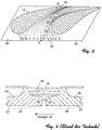
- Figure 3 shows a bottom view of two adjacent upper platforms 10. All Explanations apply equally to upper and lower platforms, the platforms are therefore generally referred to as segments 20, 20 '. 3 are the Particle trajectory lines of the hot gas stream 40 are drawn on the surface of the segments. These railway lines result from computer simulations or through direct measurement of disused components.
- the hot gas stream 40 has essentially a speed component along the gap 12. Additionally there is a cross component (also: vertical speed component), which causes the hot gas flow from one segment across the gap to the adjacent Segment leads. In Fig. 3, the cross component reverses through the action of the wing piece 14 their tracing. In a partial area 70 of the gap, between points A and B, the hot gas flow flows from the first segment 20 towards the second segment 20 '.
- a second section 74 of the gap between the reverse applies to points C and D; H. the hot gas flow flows from the second segment 20 'to the first segment 20.
- the direction of the hot gas flow is substantially parallel to the direction of the Gap 12.
- Figure 4 shows a section of the junction between two segments in detail.
- the hot gas stream 40 flows on the surfaces 22 and 22 'of segments 20 and 20' along.
- the main component of the hot gas flow 4 goes into the paper plane.
- With the specified 4 shows a section in the first partial region 70 (between the Points A and B in Fig. 3). Shows the cross component approximately as in Fig. 4 from experience shows that the first segment 20 to the second segment 20 'tears Boundary layer 24 at the gap 12. It forms on the second segment 20 ' new (reference number 24 '), but is very thin directly at the edge 26'. Thereby there is an increased thermal load on the segment material in the area the edge 26 '.
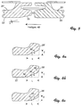
- a first embodiment according to the first aspect of the invention shows FIG. 5.
- segment 20 With a transverse component from the first segment 20 to the second In the first exemplary embodiment, segment 20 'is the one affected by the hot gas stream Edge set back by chamfering at an angle of about 30 degrees (Reference numeral 30). It was found that the boundary layer 24 of the upstream first segment 20 does not tear off at the gap 12.
- the depth of the bevel T is chosen so that the bevel does not extend to extends to the recess 18 contained in the sealing strip 16.
- the bevel 30 as just described is shown in Fig. 6a, alternative modifications are shown in detail in Figs. 6b and 6c.
- FIG. 6b is the transition between the beveled surface 30 and the The inside of the gap 28 'is not abrupt, but rounded, for example in the form of a Elliptical section 32 executed. The same applies to the transition between the beveled Surface 30 and the unchanged surface of the segment 22 '. This configuration further increases the risk of the boundary layer tearing off decreased.
- Figure 6c shows that the entire reset is also rounded off 34 can be executed. This is advantageously done in the form of an ellipse quarter as in Fig. 6c.
- the ellipse has semi-axes of length L and T.
- the danger the tearing off of the boundary layer at the gap is also very low in this alternative.
- FIG. 9 A second embodiment according to the second aspect of the invention is shown in Fig. 9.
- the section of Fig. 9 shows the case where the cross component the velocity of the hot gas flow from the first segment 20 to the second Segment 20 'shows.
- a plurality of film cooling holes 52 are attached, which are here on the back of the segment 20, associated cooling air chamber 50 with the Connect surface 22 exposed to hot gas flow.
- the cylindrical film cooling holes 52 open towards the hot gas side 22 in a funnel shape (reference number 54).
- the axis of the film cooling holes 52 faces the gap 12 and closes here with the surface 22 an angle of about 35 degrees.
- edge cooling holes 56 are provided along the edge 26 'of the second segment 20' facing the gap 12 . They are cylindrical in shape and point to the gap 12 at an angle of about 30 degrees. The Edge cooling bores 56 do not end at the one exposed to the hot gas flow Surface 22 ', but open into the gap 12. The edge cooling holes 56 provide cooling air in the gap 12, which cools the penetrating hot gas while the film cooling holes 52 near the hot gas flow Edge 26 'create a cooling air film that cools and protects edge 26'. By the selected angle between the bores 52, 56 and the surfaces 22, 22 'turbulence and thus aerodynamic losses are avoided as far as possible. It is particularly important to ensure that the angle of the edge cooling holes 56 is kept so flat that the emerging cooling air is not immediately in the hot gas is blown, otherwise there would be severe losses, since the cooling air blows against the direction of flow of the hot gas.
- the gap in which the hot gas flow from the first segment 20 to the second segment The arrangement of the film cooling bores 52 and edge cooling bores flows 20 ' 56 as described above.
- the arrangement of the film cooling holes 52 and edge cooling holes 56th interchanged the film cooling holes 52 are thus along the gap 12 facing Edge 26 'of the second segment 20' attached, and the edge cooling holes 56 are along the edge 26 of the first facing the gap 12 Segments 20 attached.
- the hot gas flow is substantially parallel to the Flow towards the gap.
- this transition area 72 are in the second Aspect of the invention along the edge 26, 26 'of gap 12 facing each of the two segments 20, 20 'edge cooling holes 56 attached, film cooling holes 52 are missing there.
- the film cooling holes 52 and the edge cooling holes 56 are preferably in relation to one another arranged laterally offset, as schematically in the bottom view of Figure 10 shown.
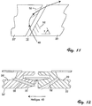
- the film cooling holes have 52 and the edge cooling bores 56 have a lateral angle of attack ⁇ such that that the axes of the holes in all areas approximately along the direction of the hot gas stream 40 show. 11 are only for the sake of clarity the film cooling holes 52 drawn in, corresponding edge cooling holes 56 are also included in a preferred embodiment.
- a third embodiment (Fig. 12), the first and second aspects of the invention combined with advantage.
- film cooling holes 52 and edge cooling holes 56 attached as in the second embodiment.
- the hot gas edge of each segment as in the first embodiment beveled.
- the chamfer 30 and the edge cooling holes 56 are coordinated so that the depth of the bevel 30 up to the opening of the edge cooling bore 56 on the inside 28 'of the gap 12 enough.
- the gap-side end region of the edge cooling bores 56 of the bevel 30 detects, and the edge cooling holes 56 remains open, too if the gap width due to manufacturing tolerances or transient conditions in the Operation should be reduced to zero.
- the design of the segments in the individual Sub-areas are described as in the first or second embodiment.
- FIG. 13 there are also film cooling holes 52 and edge cooling bores 56 as in the second exemplary embodiment, and the hot gas edge of each segment as in the first Embodiment beveled.
- the depth of the bevel 30 does not reach the edge cooling holes 56 here.
- the inner side 26 facing the gap 12 With an approximately parabolic Provide recess 58 so that the emerging from the edge cooling hole Cooling air flow 60 is deflected at the recess 58.
- the cooling air stream 60 leaves through the deflection the gap 12 on the surface 22 'substantially parallel to the hot gas flow 40.
- the partial area 70 of the Gap in which the hot gas flow is a speed component of the first Has segment 20 to the second segment 20 ', along the gap 12 facing Edge 26 of the first segment has a plurality of edge cooling holes 62 attached. These edge cooling bores 62 form one with the surface 22 Angle ⁇ , here about 40 degrees. The edge cooling holes 62 do not end at the surface 22 exposed to the hot gas stream 40, but open into the gap 12. The edge 26 'of the second segment 20' acted upon by the hot gas stream 40 is like in the first embodiment at an angle ⁇ , here about 30 degrees, beveled.
- the cooling air flow 64 occurs substantially parallel to the hot gas flow direction from what unwanted turbulence and aerodynamic loss avoids and leads to an optimized effect of the cooling air.
Landscapes
- Engineering & Computer Science (AREA)
- Mechanical Engineering (AREA)
- General Engineering & Computer Science (AREA)
- Physics & Mathematics (AREA)
- Fluid Mechanics (AREA)
- Turbine Rotor Nozzle Sealing (AREA)
Abstract
Description
- Fig. 1
- ein schematische perspektivische Ansicht der Leitschaufelplattformen einer Gasturbine;
- Fig. 2
- eine Seitenansicht der Leitschaufelplattform aus Richtung 2 von Fig. 1;
- Fig. 3
- eine Untersicht der unteren Plattform aus der Richtung 3-3 von Fig. 2 mit eingezeichneten Partikeltrajektorien des Heißgasstroms;
- Fig. 4
- einen Schnitt der Anschlußstelle zweier Plattformsegmente in Richtung 4-4 von Fig. 2 (Stand der Technik);
- Fig. 5
- einen Schnitt wie Fig. 4, entsprechend einem ersten Ausführungsbeispiel der Erfindung;
- Fig. 6a
- eine Detailansicht von Fig. 5 im Bereich der Abschrägung/Abrundung des stromabwärtigen Segments;
- Fig. 6b
- eine Detailansicht einer Abwandlung von Fig. 5 im Bereich der Abschrägung/Abrundung des stromabwärtigen Segments;
- Fig. 6c
- eine Detailansicht einer weiteren Abwandlung von Fig. 5 im Bereich der Abschrägung/Abrundung des stromabwärtigen Segments;
- Fig. 7
- eine Untersicht wie Fig. 3, entsprechend dem ersten Ausführungsbeispiel der Erfindung;
- Fig. 8
- eine perspektivische Ansicht zweier Segmente einer Leitschaufel einer Hochdruckturbine entsprechend dem ersten Ausführungsbeispiel der Erfindung;
- Fig. 9
- einen Schnitt wie Fig. 4, entsprechend einem zweiten Ausführungsbeispiel der Erfindung;
- Fig. 10
- eine schematische Auf- oder Untersicht eines Teilbereichs zweier Segmente entsprechend einer Ausgestaltung des zweiten Ausfühtungsbeispiels der Erfindung;
- Fig. 11
- eine schematische Auf- oder Untersicht zweiter Segmente entsprechend einer weiteren Ausgestaltung des zweiten Ausführungsbeispiels der Erfindung;
- Fig. 12
- einen Schnitt wie Fig. 4, entsprechend einem dritten Ausführungsbeispiel der Erfindung;
- Fig. 13
- einen Schnitt wie Fig. 4, entsprechend einem vierten Ausführungsbeispiel der Erfindung;
- Fig. 14
- einen Schnitt wie Fig. 4, entsprechend einem fünften Ausführungsbeispiel der Erfindung;
- 10
- obere Plattform
- 10'
- untere Plattform
- 12
- Spalt
- 14
- Tragflächenstück
- 16
- Dichtstreifen
- 18
- Aussparung im Segmentinneren
- 20
- erstes Segment
- 20'
- zweites Segment
- 22, 22'
- dem Heißgasstrom ausgesetzte Oberflächen der Segmente
- 24, 24'
- Grenzschicht
- 26, 26'
- dem Spalt zugewandte Kante der Segmente
- 28, 28'
- Innenseite des Segmente
- 30
- abgeschrägte Oberfläche
- 32
- gradueller Übergang der Abschrägung
- 34
- abgerundete Oberfläche
- 40
- Heißgasstrom
- 50, 50'
- Kühlluftkammer
- 52
- Filmkühlbohrung
- 54
- trichterförmige Öffnung der Filmkühlbohrung
- 56
- Kantenkühlbohrung
- 58
- konkave Aussparung
- 60
- Kühlluftstrom
- 62
- Kantenkühlbohrung (alternative Anordnung)
- 64
- Kühlluftstrom
- 70
- erster Teilbereich des Spalts
- 72
- Übergangsbereich
- 74
- zweiter Teilbereich des Spalts
Claims (25)
- Segmentanordnung für Plattformen, insbesondere in einer Gasturbine, an deren Oberfläche ein Heißgasstrom (40) entlangströmt, mit nebeneinander angeordneten, jeweils durch einen Spalt (12) voneinander getrennten Segmenten (20, 20'), wobei in mindestens einem Teilbereich (70) des Spalts (12) der Heißgasstrom (40) eine Geschwindigkeitskomponente senkrecht zur Richtung des Spaltes, von einem ersten Segment (20) zu einem zweiten Segment (20') aufweist, dadurch gekennzeichnet, daß in besagtem Teilbereich (70) die dem Spalt (12) zugewandte Kante (26') der Oberfläche (22') des zweiten Segments (22') abgeschrägt (30) oder abgerundet (34) ist.
- Segmentanordnung nach Anspruch 1, dadurch gekennzeichnet, daß in einem zweiten Teilbereich (74) des Spalts (12) der Heißgasstrom (40) eine Geschwindigkeitskomponente senkrecht zur Richtung des Spaltes, von dem zweiten Segment (20') zu dem ersten Segment (20) aufweist, und in besagtem Teilbereich (74) die dem Spalt (12) zugewandte Kante (26) der Oberfläche (22) des ersten Segments (20) abgeschrägt (30) oder abgerundet (34) ist.
- Segmentanordnung nach Anspruch 2, dadurch gekennzeichnet, daß zwischen dem ersten und zweiten Teilbereich (70, 74) ein Übergangsbereich (72) angeordnet ist, in dem der Heißgasstrom (40) im wesentlichen entlang der Richtung des Spalts (12) strömt, und daß in besagtem Übergangsbereich (72) die Abschrägung (30) oder Abrundung (34) des ersten und zweiten Teilbereiches (70, 74) allmählich auf Null zurückgeführt ist.
- Segmentanordnung nach einem der Ansprüche 1 bis 3, wobei die besagten Kanten (26, 26') der Segmente (20, 20') unter einem Winkel α abgeschrägt sind, und α zwischen 1° und 60°, bevorzugt zwischen 20° und 40° liegt.
- Segmentanordnung nach Anspruch 4, wobei der Übergang zwischen den abgeschrägten Flächen (30) und der Innenseite (28) jedes Segments (20), und/oder der Übergang zwischen den abgeschrägten Flächen (30) und den nicht abschrägten Oberflächen (22) jedes Segments (20) in Form eines Ellipsenteilstücks (32) abgerundet ist.
- Segmentanordnung nach einem der Ansprüche 1 bis 3, wobei die besagten Kanten (26, 26') der Segmente (20, 20') in Form eines Ellipsenviertels (34) abgerundet sind, und die Ellipse Halbachsen der Länge L bzw. T aufweist, wobei der Winkel α = arctan T/L zwischen 1° und 60°, bevorzugt zwischen 20° und 40° liegt.
- Segmentanordnung nach einem der vorigen Ansprüche, wobei in dem Spalt (12) ein Dichtstreifen (16) in einer Aussparung (18) angeordnet ist, und die Tiefe der Abschrägung (30) oder Abrundung (34) stets so klein gewählt ist, daß die Abschrägung (30) oder Abrundung (34) die Aussparung (18) nicht erreicht.
- Segmentanordnung für Plattformen, insbesondere in einer Gasturbine, an deren Oberfläche ein Heißgasstrom (40) entlangströmt, mit nebeneinander angeordneten, jeweils durch einen Spalt (12) voneinander getrennten Segmenten (20, 20'), wobei in mindestens einem Teilbereich (70) des Spalts (12) der Heißgasstrom (40) eine Geschwindigkeitskomponente senkrecht zur Richtung des Spaltes, von einem ersten Segment (20) zu einem zweiten Segment (20') aufweist, dadurch gekennzeichnet, daß in besagtem Teilbereich (70) entlang der dem Spalt (12) zugewandten Kante (26) des ersten Segments (20) zumindest eine Filmkühlbohrung (52) eine dem ersten Segment zugeordnete Kühlluftkammer (50) mit der dem Heißgasstrom (40) ausgesetzten Oberfläche (22) verbindet, und/oder daß in besagtem Teilbereich (70) entlang der dem Spalt (12) zugewandten Kante (26') des zweiten Segments (20') zumindest eine Kantenkühlbohrung (56) eine dem zweiten Segment zugeordnete Kühlluftkammer (50') mit der Innenseite (28') des Spalts (12) verbindet.
- Segmentanordnung nach Anspruch 8, dadurch gekennzeichnet, daß in einem zweiten Teilbereich (74) des Spalts (12) der Heißgasstrom (40) eine Geschwindigkeitskomponente senkrecht zur Richtung des Spaltes, von dem zweiten Segment (20') zu dem ersten Segment (20) aufweist, und in besagtem Teilbereich (74) entlang der dem Spalt (12) zugewandten Kante (26') des zweiten Segments (20') zumindest eine Filmkühlbohrung (52) die dem zweiten Segment zugeordnete Kühlluftkammer (50') mit der dem Heißgasstrom (40) ausgesetzten Oberfläche (22') verbindet, und/oder daß in besagtem Teilbereich (74) entlang der dem Spalt (12) zugewandten Kante (26) des ersten Segments (20) zumindest eine Kantenkühlbohrung (56) die dem ersten Segment zugeordnete Kühlluftkammer (50) mit der Innenseite (28) des Spalts (12) verbindet.
- Segmentanordnung nach Anspruch 9, dadurch gekennzeichnet, daß zwischen dem ersten und zweiten Teilbereich (70, 74) ein Übergangsbereich (72) angeordnet ist, in dem der Heißgasstrom (40) im wesentlichen entlang der Richtung des Spalts (12) strömt, und daß in besagtem Übergangsbereich (72) entlang der dem Spalt (12) zugewandten Kanten (26, 26') der beiden Segmente (20, 20') zumindest eine Kantenkühlbohrung (56) zumindest eine der den Segmenten (20, 20') zugeordneten Kühlluftkammern (50, 50') mit der Innenseite (28, 28') des Spalts (12) verbindet.
- Segmentanordnung nach einem der Ansprüche 8 bis 10, bei der die Achsen der Filmkühlbohrungen (52) auf den Spalt (12) zuweisen, und mit der Oberfläche (22) des besagte Filmkühlbohrungen (52) enthaltenden Segments (20) einen Winkel zwischen 10° und 50°, bevorzugt zwischen 25° und 45° einschließen, und/oder bei der die Achsen die Kantenkühlbohrungen (56) auf den Spalt (12) zuweisen, und mit der Oberfläche (22') des besagte Kantenkühlbohrungen (56) enthaltenden Segments (20') einen Winkel zwischen 5° und 50°, bevorzugt zwischen 20° und 40° einschließen.
- Segmentanordnung nach einem der Ansprüche 8 bis 11, bei der die Filmkühlbohrungen (52) zylindrisch und/oder trichterförmig geformt sind, und/oder bei der die Kantenkühlbohrungen (56) zylindrisch geformt sind.
- Segmentanordnung nach einem der Ansprüche 8 bis 12, bei der die Filmkühlbohrungen (52) auf der der Kühlluftkammer (50) zugewandten Seite zylindrisch geformt sind, und auf der Heißgasseite (22) eine trichterförmige Öffnung (54) aufweisen.
- Segmentanordnung nach einem der Ansprüche 8 bis 13, bei der die Filmkühlbohrungen (52) und die Kantenkühlbohrungen (56) gegeneinander lateral versetzt angeordnet sind.
- Segmentanordnung nach einem der Ansprüche 8 bis 14, bei der die Filmkühlbohrungen (52) und/oder die Kantenkühlbohrungen (56) einen lateralen Anstellwinkel γ aufweisen.
- Segmentanordnung nach Anspruch 15, bei der der laterale Anstellwinkel γ so gewählt ist, daß die Achsen Filmkühlbohrungen (52) und/oder der Kantenkühlbohrungen (56) im wesentlichen entlang der Richtung des Heißgasstroms (40) zeigen.
- Segmentanordnung nach einem der Ansprüche 8 bis 16, bei der jeweils der vom Heißgasstrom (40) beaufschlagte Teilbereich (70, 74) der Kante (26, 26') jedes Segments (20, 20') abgeschrägt (30) oder abgerundet (34) ist.
- Segmentanordnung nach einem der Ansprüche 10 bis 16, bei der jeweils der vom Heißgasstrom (40) beaufschlagte Teilbereich (70, 74) der Kante (26, 26') jedes Segments (20, 20') abgeschrägt (30) oder abgerundet (34) ist, und bei der im besagten Übergangsbereich (72) die Abschrägung (30) oder Abrundung (34) der besagten Teilbereiche (70,74) allmählich auf Null zurückgeführt ist.
- Segmentanordnung nach einem der Ansprüche 17 bis 18, bei der die besagten Kanten (26, 26') der Segmente (20, 20') unter einem Winkel α abgeschrägt sind, und α zwischen 1° und 60°, bevorzugt zwischen 20° und 40° liegt.
- Segmentanordnung nach Anspruch 19, bei der der Übergang zwischen den abgeschrägten Flächen (30) und der Innenseite (28) jedes Segments (20), und/oder der Übergang zwischen den abgeschrägten Flächen (30) und den nicht abschrägten Oberflächen (22) jedes Segments (20) in Form eines Ellipsenteilstücks (32) abgerundet ist.
- Segmentanordnung nach einem der Ansprüche 17 bis 18, wobei die besagten Kanten (26, 26') der Segmente (20, 20') in Form eines Ellipsenviertels (34) abgerundet sind, und die Ellipse Halbachsen der Länge L bzw. T aufweist, wobei der Winkel α = arctan T/L zwischen 1° und 60°, bevorzugt zwischen 20° und 40° liegt.
- Segmentanordnung nach einem der Ansprüche 17 bis 21, wobei die Tiefe der Abschrägungen (30) oder Abrundungen (34) so gewählt ist, daß sie bis zu den Öffnungen der Kantenkühlbohrungen (56) an der Innenseite (28') des Spalts (12) reichen.
- Segmentanordnung nach einem der Ansprüche 17 bis 21, wobei die Tiefe der Abschrägungen (30) oder Abrundungen (34) so gewählt ist, daß sie die Öffnungen der Kantenkühlbohrungen (56) an der Innenseite (28') des Spalts (12) nicht erreichen, und bei der die Innenseite (28) jedes mit Filmkühlbohrungen versehenen Segments (20) mit einer konkaven Aussparung (58) versehen ist.
- Segmentanordnung nach einem der Ansprüche 17 bis 23, wobei in dem Spalt (12) ein Dichtstreifen (16) in einer Aussparung (18) angeordnet ist, und die Tiefe der Abschrägung (30) oder Abrundung (34) stets so klein gewählt ist, daß die Abschrägung (30) oder Abrundung (34) die Aussparung (18) nicht erreicht.
- Segmentanordnung nach einem der Ansprüche 1 bis 7, bei der jeweils in dem Teilbereich (70) eines Segments (20), der einem mit einer Abschrägung (30) oder Abrundung (34) versehenen Teilbereich eines weiteren Segments (20') am Spalt (12) gegenüber liegt, zumindest eine Kantenkühlbohrung (62) entlang der dem Spalt (12) zugewandten Kante (26) des besagten Segments (20) eine dem besagten Segment (20) zugeordnete Kühlluftkammer (50) mit der Innenseite (28) des Spalts (12) verbindet, und bei der die Achsen der Kantenkühlbohrungen (62) mit der Oberfläche (22) des besagten Segments (20) einen Winkel β einschließen, wobei β in einem Intervall von 30° um den durch die Abschrägung (30) oder Abrundung (34) definierten Winkel α herum liegt.
Priority Applications (6)
| Application Number | Priority Date | Filing Date | Title |
|---|---|---|---|
| EP97810659A EP0902167B1 (de) | 1997-09-15 | 1997-09-15 | Kühlvorrichtung für Gasturbinenkomponenten |
| EP02017183A EP1260678B1 (de) | 1997-09-15 | 1997-09-15 | Segmentanordnung für Plattformen |
| DE59710924T DE59710924D1 (de) | 1997-09-15 | 1997-09-15 | Kühlvorrichtung für Gasturbinenkomponenten |
| US09/151,809 US6261053B1 (en) | 1997-09-15 | 1998-09-14 | Cooling arrangement for gas-turbine components |
| CNB981192734A CN1288329C (zh) | 1997-09-15 | 1998-09-15 | 导板的扇形体结构 |
| JP10261684A JPH11148303A (ja) | 1997-09-15 | 1998-09-16 | プラットホームのためのセグメント装置 |
Applications Claiming Priority (1)
| Application Number | Priority Date | Filing Date | Title |
|---|---|---|---|
| EP97810659A EP0902167B1 (de) | 1997-09-15 | 1997-09-15 | Kühlvorrichtung für Gasturbinenkomponenten |
Related Child Applications (1)
| Application Number | Title | Priority Date | Filing Date |
|---|---|---|---|
| EP02017183A Division EP1260678B1 (de) | 1997-09-15 | 1997-09-15 | Segmentanordnung für Plattformen |
Publications (2)
| Publication Number | Publication Date |
|---|---|
| EP0902167A1 true EP0902167A1 (de) | 1999-03-17 |
| EP0902167B1 EP0902167B1 (de) | 2003-10-29 |
Family
ID=8230377
Family Applications (2)
| Application Number | Title | Priority Date | Filing Date |
|---|---|---|---|
| EP02017183A Expired - Lifetime EP1260678B1 (de) | 1997-09-15 | 1997-09-15 | Segmentanordnung für Plattformen |
| EP97810659A Expired - Lifetime EP0902167B1 (de) | 1997-09-15 | 1997-09-15 | Kühlvorrichtung für Gasturbinenkomponenten |
Family Applications Before (1)
| Application Number | Title | Priority Date | Filing Date |
|---|---|---|---|
| EP02017183A Expired - Lifetime EP1260678B1 (de) | 1997-09-15 | 1997-09-15 | Segmentanordnung für Plattformen |
Country Status (5)
| Country | Link |
|---|---|
| US (1) | US6261053B1 (de) |
| EP (2) | EP1260678B1 (de) |
| JP (1) | JPH11148303A (de) |
| CN (1) | CN1288329C (de) |
| DE (1) | DE59710924D1 (de) |
Cited By (13)
| Publication number | Priority date | Publication date | Assignee | Title |
|---|---|---|---|---|
| US6579061B1 (en) * | 2001-07-27 | 2003-06-17 | General Electric Company | Selective step turbine nozzle |
| EP1219781A3 (de) * | 2000-12-22 | 2004-01-21 | ALSTOM (Switzerland) Ltd | Vorrichtung und Verfahren zur Kühlung einer Plattform einer Turbinenschaufel |
| EP1749967A2 (de) | 2005-08-02 | 2007-02-07 | Rolls-Royce plc | Kühlsystem für eine Gasturbine |
| EP1674659A3 (de) * | 2004-12-02 | 2007-03-21 | General Electric Company | Statorbeschaufelung mit abgerundeter Abwärtsstufe in der Plattform |
| EP1621735A3 (de) * | 2004-07-28 | 2008-12-17 | Rolls-Royce Deutschland Ltd & Co KG | Gasturbinenrotor |
| EP2818641A1 (de) * | 2013-06-26 | 2014-12-31 | Siemens Aktiengesellschaft | Turbinenschaufel mit gestufter und abgeschrägter Plattformkante |
| EP2952682A1 (de) * | 2014-06-06 | 2015-12-09 | United Technologies Corporation | Schaufel für ein gasturbinenkraftwerk mit einer gekühlten plattform |
| EP2971674A4 (de) * | 2013-03-14 | 2016-11-02 | United Technologies Corp | Kühlung der statorschaufelplattform eines gasturbinenmotors |
| EP3159487A1 (de) * | 2015-03-04 | 2017-04-26 | Rolls-Royce Deutschland Ltd & Co KG | Stator einer turbine einer gasturbine mit verbesserter kühlluftführung |
| EP3090143A4 (de) * | 2013-12-09 | 2017-12-06 | United Technologies Corporation | Gasturbinenmotorkomponentenanschlussflächenoberflächen |
| WO2019160547A1 (en) * | 2018-02-15 | 2019-08-22 | Siemens Aktiengesellschaft | Assembly of turbine blades and corresponding article of manufacture |
| EP3748127A1 (de) * | 2019-06-07 | 2020-12-09 | Rolls-Royce plc | Turbomaschinenschaufelkühlung |
| CN114382555A (zh) * | 2020-10-16 | 2022-04-22 | 中国航发商用航空发动机有限责任公司 | 导叶缘板、导叶、涡轮导向器及导叶缘板的设计方法 |
Families Citing this family (60)
| Publication number | Priority date | Publication date | Assignee | Title |
|---|---|---|---|---|
| JP2002201913A (ja) * | 2001-01-09 | 2002-07-19 | Mitsubishi Heavy Ind Ltd | ガスタービンの分割壁およびシュラウド |
| US6554566B1 (en) * | 2001-10-26 | 2003-04-29 | General Electric Company | Turbine shroud cooling hole diffusers and related method |
| US6672832B2 (en) | 2002-01-07 | 2004-01-06 | General Electric Company | Step-down turbine platform |
| JP4481822B2 (ja) * | 2002-08-14 | 2010-06-16 | ボルボ エアロ コーポレイション | 静翼構成部材の製造方法 |
| US6910854B2 (en) * | 2002-10-08 | 2005-06-28 | United Technologies Corporation | Leak resistant vane cluster |
| US6758651B2 (en) * | 2002-10-16 | 2004-07-06 | Mitsubishi Heavy Industries, Ltd. | Gas turbine |
| WO2004074640A1 (de) * | 2003-02-19 | 2004-09-02 | Alstom Technology Ltd | Dichtungsanordnung, insbesondere für die schaufelsegmente von gasturbinen |
| US20050067788A1 (en) * | 2003-09-25 | 2005-03-31 | Siemens Westinghouse Power Corporation | Outer air seal assembly |
| GB0328952D0 (en) * | 2003-12-12 | 2004-01-14 | Rolls Royce Plc | Nozzle guide vanes |
| GB0523106D0 (en) * | 2005-11-12 | 2005-12-21 | Rolls Royce Plc | A cooliing arrangement |
| US7632071B2 (en) * | 2005-12-15 | 2009-12-15 | United Technologies Corporation | Cooled turbine blade |
| US7922444B2 (en) * | 2007-01-19 | 2011-04-12 | United Technologies Corporation | Chamfer rail pockets for turbine vane shrouds |
| EP1975372A1 (de) * | 2007-03-28 | 2008-10-01 | Siemens Aktiengesellschaft | Exzentrische Anfasung am Einfüllstutzen in einem Strömungskanal |
| ATE466169T1 (de) * | 2007-04-05 | 2010-05-15 | Alstom Technology Ltd | Spaltdichtung für schaufeln einer turbomaschine |
| US8128349B2 (en) * | 2007-10-17 | 2012-03-06 | United Technologies Corp. | Gas turbine engines and related systems involving blade outer air seals |
| US10286407B2 (en) | 2007-11-29 | 2019-05-14 | General Electric Company | Inertial separator |
| US8534993B2 (en) | 2008-02-13 | 2013-09-17 | United Technologies Corp. | Gas turbine engines and related systems involving blade outer air seals |
| DE102008015207A1 (de) * | 2008-03-20 | 2009-09-24 | Rolls-Royce Deutschland Ltd & Co Kg | Fluid-Injektor-Düse |
| DE102008017844A1 (de) * | 2008-04-08 | 2009-10-15 | Rolls-Royce Deutschland Ltd & Co Kg | Strömungsmaschine mit Fluid-Injektorbaugruppe |
| GB2468848B (en) * | 2009-03-23 | 2011-10-26 | Rolls Royce Plc | An assembly for a turbomachine |
| JP5426305B2 (ja) * | 2009-09-30 | 2014-02-26 | 株式会社東芝 | ターボ機械 |
| US8517680B1 (en) * | 2010-04-23 | 2013-08-27 | Florida Turbine Technologies, Inc. | Turbine blade with platform cooling |
| RU2543101C2 (ru) * | 2010-11-29 | 2015-02-27 | Альстом Текнолоджи Лтд | Осевая газовая турбина |
| US8961135B2 (en) * | 2011-06-29 | 2015-02-24 | Siemens Energy, Inc. | Mateface gap configuration for gas turbine engine |
| US20130315745A1 (en) * | 2012-05-22 | 2013-11-28 | United Technologies Corporation | Airfoil mateface sealing |
| EP3042045A4 (de) * | 2013-09-06 | 2017-06-14 | United Technologies Corporation | Geneigte boas-intersegment-geometrie |
| WO2015105654A1 (en) | 2014-01-08 | 2015-07-16 | United Technologies Corporation | Clamping seal for jet engine mid-turbine frame |
| EP3099921B1 (de) * | 2014-01-28 | 2019-01-16 | United Technologies Corporation | Prallstruktur für einen mittelturbinenrahmen eines strahltriebwerks |
| KR101833660B1 (ko) * | 2014-04-03 | 2018-02-28 | 미츠비시 히타치 파워 시스템즈 가부시키가이샤 | 날개열, 가스터빈 |
| US11033845B2 (en) | 2014-05-29 | 2021-06-15 | General Electric Company | Turbine engine and particle separators therefore |
| WO2016032585A2 (en) | 2014-05-29 | 2016-03-03 | General Electric Company | Turbine engine, components, and methods of cooling same |
| US9915176B2 (en) | 2014-05-29 | 2018-03-13 | General Electric Company | Shroud assembly for turbine engine |
| WO2016025056A2 (en) | 2014-05-29 | 2016-02-18 | General Electric Company | Turbine engine and particle separators therefore |
| US10180082B2 (en) * | 2014-06-05 | 2019-01-15 | Rolls-Royce Corporation | Fan case |
| US10167725B2 (en) | 2014-10-31 | 2019-01-01 | General Electric Company | Engine component for a turbine engine |
| US10036319B2 (en) | 2014-10-31 | 2018-07-31 | General Electric Company | Separator assembly for a gas turbine engine |
| US20160258295A1 (en) * | 2015-03-02 | 2016-09-08 | General Electric Company | Turbine bucket platform for controlling incursion losses |
| US10174620B2 (en) | 2015-10-15 | 2019-01-08 | General Electric Company | Turbine blade |
| US10428664B2 (en) | 2015-10-15 | 2019-10-01 | General Electric Company | Nozzle for a gas turbine engine |
| US9988936B2 (en) | 2015-10-15 | 2018-06-05 | General Electric Company | Shroud assembly for a gas turbine engine |
| US11156117B2 (en) * | 2016-04-25 | 2021-10-26 | Raytheon Technologies Corporation | Seal arc segment with sloped circumferential sides |
| US10704425B2 (en) | 2016-07-14 | 2020-07-07 | General Electric Company | Assembly for a gas turbine engine |
| GB2559804A (en) * | 2017-02-21 | 2018-08-22 | Siemens Ag | Heatshield for a gas turbine |
| US10480333B2 (en) * | 2017-05-30 | 2019-11-19 | United Technologies Corporation | Turbine blade including balanced mateface condition |
| CN111936725B (zh) * | 2018-03-30 | 2022-08-16 | 西门子能源全球两合公司 | 涡轮机护罩段之间的密封布置 |
| US10927692B2 (en) * | 2018-08-06 | 2021-02-23 | General Electric Company | Turbomachinery sealing apparatus and method |
| US11326518B2 (en) * | 2019-02-07 | 2022-05-10 | Raytheon Technologies Corporation | Cooled component for a gas turbine engine |
| US11359505B2 (en) * | 2019-05-04 | 2022-06-14 | Raytheon Technologies Corporation | Nesting CMC components |
| US12442309B2 (en) * | 2019-09-12 | 2025-10-14 | General Electric Company | Nozzle assembly for turbine engine |
| US11098612B2 (en) * | 2019-11-18 | 2021-08-24 | Raytheon Technologies Corporation | Blade outer air seal including cooling trench |
| US11384654B2 (en) | 2019-11-18 | 2022-07-12 | Raytheon Technologies Corporation | Mateface for blade outer air seals in a gas turbine engine |
| DE102020103898B4 (de) * | 2020-02-14 | 2025-10-02 | Doosan Enerbility Co., Ltd. | Gasturbinenschaufel zur Wiederverwendung von Kühlluft und Turbomaschinenanordnung und damit versehene Gasturbine |
| US11781440B2 (en) * | 2021-03-09 | 2023-10-10 | Rtx Corporation | Scalloped mateface seal arrangement for CMC platforms |
| US12098643B2 (en) | 2021-03-09 | 2024-09-24 | Rtx Corporation | Chevron grooved mateface seal |
| US11415010B1 (en) * | 2021-07-05 | 2022-08-16 | Doosan Enerbility Co., Ltd. | Turbine nozzle and gas turbine including the same |
| GB202212532D0 (en) * | 2022-08-30 | 2022-10-12 | Rolls Royce Plc | Turbine shroud segment and its manufacture |
| FR3139595B1 (fr) * | 2022-09-09 | 2024-12-13 | Safran | Aube directrice destinée à être fixée sur une virole de stator d’un moteur à turbine à gaz |
| EP4343119A1 (de) * | 2022-09-23 | 2024-03-27 | Siemens Energy Global GmbH & Co. KG | Ringsegment für gasturbinentriebwerk |
| CN119933805A (zh) * | 2023-11-03 | 2025-05-06 | 中国航发商用航空发动机有限责任公司 | 动叶缘板、动叶及动叶缘板设计方法 |
| US12385407B1 (en) * | 2024-05-17 | 2025-08-12 | Rtx Corporation | Additively manufactured turbine vane cluster |
Citations (3)
| Publication number | Priority date | Publication date | Assignee | Title |
|---|---|---|---|---|
| WO1994012765A1 (en) * | 1992-11-24 | 1994-06-09 | United Technologies Corporation | Rotor blade with cooled integral platform |
| US5374161A (en) * | 1993-12-13 | 1994-12-20 | United Technologies Corporation | Blade outer air seal cooling enhanced with inter-segment film slot |
| GB2280935A (en) * | 1993-06-12 | 1995-02-15 | Rolls Royce Plc | Cooled sealing strip for nozzle guide vane segments |
Family Cites Families (19)
| Publication number | Priority date | Publication date | Assignee | Title |
|---|---|---|---|---|
| CH525419A (de) * | 1970-12-18 | 1972-07-15 | Bbc Sulzer Turbomaschinen | Dichtungsvorrichtung für Turbomaschinen |
| US3975114A (en) * | 1975-09-23 | 1976-08-17 | Westinghouse Electric Corporation | Seal arrangement for turbine diaphragms and the like |
| US4135857A (en) * | 1977-06-09 | 1979-01-23 | United Technologies Corporation | Reduced drag airfoil platforms |
| US4311432A (en) * | 1979-11-20 | 1982-01-19 | United Technologies Corporation | Radial seal |
| JPS6022002A (ja) * | 1983-07-18 | 1985-02-04 | Hitachi Ltd | タ−ボ機械の翼構造 |
| US4650394A (en) * | 1984-11-13 | 1987-03-17 | United Technologies Corporation | Coolable seal assembly for a gas turbine engine |
| JPS6319003U (de) * | 1986-07-23 | 1988-02-08 | ||
| US4902198A (en) * | 1988-08-31 | 1990-02-20 | Westinghouse Electric Corp. | Apparatus for film cooling of turbine van shrouds |
| US5020970A (en) * | 1989-07-13 | 1991-06-04 | Dresser-Rand Company | Fluid-handling, bladed rotor |
| JPH03213602A (ja) * | 1990-01-08 | 1991-09-19 | General Electric Co <Ge> | ガスタービンエンジンの当接セグメントを連結する自己冷却式ジョイント連結構造 |
| US5088888A (en) * | 1990-12-03 | 1992-02-18 | General Electric Company | Shroud seal |
| US5415526A (en) * | 1993-11-19 | 1995-05-16 | Mercadante; Anthony J. | Coolable rotor assembly |
| JPH08114101A (ja) * | 1994-10-19 | 1996-05-07 | Hitachi Ltd | ガスタービンのシュラウド装置 |
| US5531457A (en) * | 1994-12-07 | 1996-07-02 | Pratt & Whitney Canada, Inc. | Gas turbine engine feather seal arrangement |
| JPH08177529A (ja) * | 1994-12-20 | 1996-07-09 | Toshiba Corp | ガスタービン |
| US5823741A (en) * | 1996-09-25 | 1998-10-20 | General Electric Co. | Cooling joint connection for abutting segments in a gas turbine engine |
| US6290459B1 (en) * | 1999-11-01 | 2001-09-18 | General Electric Company | Stationary flowpath components for gas turbine engines |
| DE10019546B4 (de) * | 2000-04-20 | 2016-04-07 | Alstom Technology Ltd. | Dampfturbine mit einem einem Rotor und/oder einem Stator zugeordneten Schaufelträger |
| JP2002213207A (ja) * | 2001-01-15 | 2002-07-31 | Mitsubishi Heavy Ind Ltd | ガスタービン分割環 |
-
1997
- 1997-09-15 DE DE59710924T patent/DE59710924D1/de not_active Expired - Lifetime
- 1997-09-15 EP EP02017183A patent/EP1260678B1/de not_active Expired - Lifetime
- 1997-09-15 EP EP97810659A patent/EP0902167B1/de not_active Expired - Lifetime
-
1998
- 1998-09-14 US US09/151,809 patent/US6261053B1/en not_active Expired - Lifetime
- 1998-09-15 CN CNB981192734A patent/CN1288329C/zh not_active Expired - Fee Related
- 1998-09-16 JP JP10261684A patent/JPH11148303A/ja active Pending
Patent Citations (3)
| Publication number | Priority date | Publication date | Assignee | Title |
|---|---|---|---|---|
| WO1994012765A1 (en) * | 1992-11-24 | 1994-06-09 | United Technologies Corporation | Rotor blade with cooled integral platform |
| GB2280935A (en) * | 1993-06-12 | 1995-02-15 | Rolls Royce Plc | Cooled sealing strip for nozzle guide vane segments |
| US5374161A (en) * | 1993-12-13 | 1994-12-20 | United Technologies Corporation | Blade outer air seal cooling enhanced with inter-segment film slot |
Cited By (20)
| Publication number | Priority date | Publication date | Assignee | Title |
|---|---|---|---|---|
| EP1219781A3 (de) * | 2000-12-22 | 2004-01-21 | ALSTOM (Switzerland) Ltd | Vorrichtung und Verfahren zur Kühlung einer Plattform einer Turbinenschaufel |
| US6579061B1 (en) * | 2001-07-27 | 2003-06-17 | General Electric Company | Selective step turbine nozzle |
| EP1621735A3 (de) * | 2004-07-28 | 2008-12-17 | Rolls-Royce Deutschland Ltd & Co KG | Gasturbinenrotor |
| US7874803B2 (en) | 2004-07-28 | 2011-01-25 | Rolls-Royce Deutschland Ltd & Co Kg | Gas turbine rotor |
| EP1674659A3 (de) * | 2004-12-02 | 2007-03-21 | General Electric Company | Statorbeschaufelung mit abgerundeter Abwärtsstufe in der Plattform |
| EP1749967A2 (de) | 2005-08-02 | 2007-02-07 | Rolls-Royce plc | Kühlsystem für eine Gasturbine |
| EP1749967A3 (de) * | 2005-08-02 | 2008-07-30 | Rolls-Royce plc | Kühlsystem für eine Gasturbine |
| US7648333B2 (en) | 2005-08-02 | 2010-01-19 | Rolls-Royce Plc | Cooling arrangement |
| EP2971674A4 (de) * | 2013-03-14 | 2016-11-02 | United Technologies Corp | Kühlung der statorschaufelplattform eines gasturbinenmotors |
| US10233767B2 (en) | 2013-06-26 | 2019-03-19 | Siemens Aktiengesellschaft | Turbine blade or vane having a stepped and beveled platform edge |
| WO2014206717A1 (de) * | 2013-06-26 | 2014-12-31 | Siemens Aktiengesellschaft | Turbinenschaufel mit gestufter und abgeschrägter plattformkante |
| EP2818641A1 (de) * | 2013-06-26 | 2014-12-31 | Siemens Aktiengesellschaft | Turbinenschaufel mit gestufter und abgeschrägter Plattformkante |
| EP3090143A4 (de) * | 2013-12-09 | 2017-12-06 | United Technologies Corporation | Gasturbinenmotorkomponentenanschlussflächenoberflächen |
| EP2952682A1 (de) * | 2014-06-06 | 2015-12-09 | United Technologies Corporation | Schaufel für ein gasturbinenkraftwerk mit einer gekühlten plattform |
| EP3159487A1 (de) * | 2015-03-04 | 2017-04-26 | Rolls-Royce Deutschland Ltd & Co KG | Stator einer turbine einer gasturbine mit verbesserter kühlluftführung |
| US10041352B2 (en) | 2015-03-04 | 2018-08-07 | Rolls-Royce Deutschland Ltd & Co Kg | Stator of a turbine of a gas turbine with improved cooling air routing |
| WO2019160547A1 (en) * | 2018-02-15 | 2019-08-22 | Siemens Aktiengesellschaft | Assembly of turbine blades and corresponding article of manufacture |
| CN111699301A (zh) * | 2018-02-15 | 2020-09-22 | 西门子股份公司 | 涡轮叶片的组件和相对应的制品 |
| EP3748127A1 (de) * | 2019-06-07 | 2020-12-09 | Rolls-Royce plc | Turbomaschinenschaufelkühlung |
| CN114382555A (zh) * | 2020-10-16 | 2022-04-22 | 中国航发商用航空发动机有限责任公司 | 导叶缘板、导叶、涡轮导向器及导叶缘板的设计方法 |
Also Published As
| Publication number | Publication date |
|---|---|
| DE59710924D1 (de) | 2003-12-04 |
| US6261053B1 (en) | 2001-07-17 |
| CN1211669A (zh) | 1999-03-24 |
| EP0902167B1 (de) | 2003-10-29 |
| EP1260678B1 (de) | 2004-07-07 |
| EP1260678A1 (de) | 2002-11-27 |
| JPH11148303A (ja) | 1999-06-02 |
| CN1288329C (zh) | 2006-12-06 |
Similar Documents
| Publication | Publication Date | Title |
|---|---|---|
| EP0902167A1 (de) | Kühlvorrichtung für Gasturbinenkomponenten | |
| EP1320661B1 (de) | Gasturbinenschaufel | |
| DE2930949C2 (de) | ||
| DE69916368T2 (de) | Partikelfalle im Kühlsystem von Gasturbinen | |
| DE69932688T2 (de) | Kühlungsöffnungen für Gasturbinenkomponenten | |
| DE60018817T2 (de) | Gekühlte Gasturbinenschaufel | |
| DE3534905C2 (de) | Gekühlte hohle Turbinenschaufel | |
| DE1476796C3 (de) | Aus einem hochfesten Material integral hergestelltes Bauteil einer Gasturbinenanlage | |
| DE2718661C2 (de) | Leitschaufelgitter für eine axial durchströmte Gasturbine | |
| DE69809422T2 (de) | Wellenleistungs-turbine mit einer abgasdüse zur vermeidung von infrarotstrahlung | |
| DE69105837T2 (de) | Gekühlte Turbinenschaufel. | |
| EP1488077B1 (de) | Gekühlte turbinenschaufel | |
| DE19963349A1 (de) | Schaufel für Gasturbinen mit Drosselquerschnitt an Hinterkante | |
| EP1267039A1 (de) | Kühlkonstruktion für Schaufelblatthinterkante | |
| DE19810821A1 (de) | Gasturbinen-Dichtungsvorrichtung | |
| DE102009042857A1 (de) | Gasturbine mit Deckband-Labyrinthdichtung | |
| EP2423599A2 (de) | Verfahren zum Betrieb einer Brenneranordnung sowie Brenneranordnung der Durchführung des Verfahrens | |
| DE2037407C3 (de) | Strahlrohr mit einem Kernstromkanal und einem Mantelstromkanal | |
| EP1745195B1 (de) | Strömungsmaschinenschaufel | |
| DE10064264B4 (de) | Anordnung zur Kühlung eines Bauteils | |
| EP0992656B1 (de) | Strömungsmaschine zum Verdichten oder Entspannen eines komprimierbaren Mediums | |
| WO2008122507A1 (de) | Shiplap-anordnung | |
| WO2005068783A1 (de) | Gekühlte schaufel für eine gasturbine | |
| EP3246518A1 (de) | Leitschaufelkranz, zugehörige baugruppe und strömungsmaschine | |
| EP3473808B1 (de) | Schaufelblatt für eine innengekühlte turbinenlaufschaufel sowie verfahren zur herstellung einer solchen |
Legal Events
| Date | Code | Title | Description |
|---|---|---|---|
| PUAI | Public reference made under article 153(3) epc to a published international application that has entered the european phase |
Free format text: ORIGINAL CODE: 0009012 |
|
| AK | Designated contracting states |
Kind code of ref document: A1 Designated state(s): DE FR GB |
|
| AX | Request for extension of the european patent |
Free format text: AL;LT;LV;RO;SI |
|
| 17P | Request for examination filed |
Effective date: 19990903 |
|
| AKX | Designation fees paid |
Free format text: DE FR GB |
|
| RAP1 | Party data changed (applicant data changed or rights of an application transferred) |
Owner name: ALSTOM |
|
| 17Q | First examination report despatched |
Effective date: 20011204 |
|
| RAP1 | Party data changed (applicant data changed or rights of an application transferred) |
Owner name: ALSTOM (SWITZERLAND) LTD |
|
| GRAH | Despatch of communication of intention to grant a patent |
Free format text: ORIGINAL CODE: EPIDOS IGRA |
|
| GRAH | Despatch of communication of intention to grant a patent |
Free format text: ORIGINAL CODE: EPIDOS IGRA |
|
| GRAA | (expected) grant |
Free format text: ORIGINAL CODE: 0009210 |
|
| AK | Designated contracting states |
Kind code of ref document: B1 Designated state(s): DE FR GB |
|
| REG | Reference to a national code |
Ref country code: GB Ref legal event code: FG4D Free format text: NOT ENGLISH |
|
| REF | Corresponds to: |
Ref document number: 59710924 Country of ref document: DE Date of ref document: 20031204 Kind code of ref document: P |
|
| RAP2 | Party data changed (patent owner data changed or rights of a patent transferred) |
Owner name: ALSTOM TECHNOLOGY LTD |
|
| GBT | Gb: translation of ep patent filed (gb section 77(6)(a)/1977) |
Effective date: 20040120 |
|
| REG | Reference to a national code |
Ref country code: GB Ref legal event code: 732E |
|
| ET | Fr: translation filed | ||
| PLBE | No opposition filed within time limit |
Free format text: ORIGINAL CODE: 0009261 |
|
| STAA | Information on the status of an ep patent application or granted ep patent |
Free format text: STATUS: NO OPPOSITION FILED WITHIN TIME LIMIT |
|
| 26N | No opposition filed |
Effective date: 20040730 |
|
| REG | Reference to a national code |
Ref country code: FR Ref legal event code: TP |
|
| REG | Reference to a national code |
Ref country code: DE Ref legal event code: R082 Ref document number: 59710924 Country of ref document: DE Representative=s name: ROESLER, UWE, DIPL.-PHYS.UNIV., DE Ref country code: DE Ref legal event code: R081 Ref document number: 59710924 Country of ref document: DE Owner name: GENERAL ELECTRIC TECHNOLOGY GMBH, CH Free format text: FORMER OWNER: ALSTOM TECHNOLOGY LTD., BADEN, CH |
|
| REG | Reference to a national code |
Ref country code: FR Ref legal event code: PLFP Year of fee payment: 20 |
|
| PGFP | Annual fee paid to national office [announced via postgrant information from national office to epo] |
Ref country code: GB Payment date: 20160920 Year of fee payment: 20 Ref country code: DE Payment date: 20160921 Year of fee payment: 20 |
|
| PGFP | Annual fee paid to national office [announced via postgrant information from national office to epo] |
Ref country code: FR Payment date: 20160921 Year of fee payment: 20 |
|
| REG | Reference to a national code |
Ref country code: FR Ref legal event code: CD Owner name: ALSTOM TECHNOLOGY LTD, CH Effective date: 20161110 |
|
| REG | Reference to a national code |
Ref country code: DE Ref legal event code: R071 Ref document number: 59710924 Country of ref document: DE |
|
| REG | Reference to a national code |
Ref country code: GB Ref legal event code: 732E Free format text: REGISTERED BETWEEN 20170824 AND 20170830 |
|
| REG | Reference to a national code |
Ref country code: GB Ref legal event code: PE20 Expiry date: 20170914 |
|
| PG25 | Lapsed in a contracting state [announced via postgrant information from national office to epo] |
Ref country code: GB Free format text: LAPSE BECAUSE OF EXPIRATION OF PROTECTION Effective date: 20170914 |
|
| REG | Reference to a national code |
Ref country code: FR Ref legal event code: TP Owner name: ANSALDO ENERGIA IP UK LIMITED, GB Effective date: 20171221 |