EP0902193B1 - Kolbenspeicher mit Tiefenfiltrationsdichtung - Google Patents
Kolbenspeicher mit Tiefenfiltrationsdichtung Download PDFInfo
- Publication number
- EP0902193B1 EP0902193B1 EP98113168A EP98113168A EP0902193B1 EP 0902193 B1 EP0902193 B1 EP 0902193B1 EP 98113168 A EP98113168 A EP 98113168A EP 98113168 A EP98113168 A EP 98113168A EP 0902193 B1 EP0902193 B1 EP 0902193B1
- Authority
- EP
- European Patent Office
- Prior art keywords
- piston
- separating
- accumulator
- sealing
- sealing device
- Prior art date
- Legal status (The legal status is an assumption and is not a legal conclusion. Google has not performed a legal analysis and makes no representation as to the accuracy of the status listed.)
- Expired - Lifetime
Links
- 238000007789 sealing Methods 0.000 title claims abstract description 55
- 239000012530 fluid Substances 0.000 claims abstract description 29
- 229920001971 elastomer Polymers 0.000 claims abstract description 8
- 239000000806 elastomer Substances 0.000 claims abstract description 7
- 230000000694 effects Effects 0.000 claims description 6
- 238000013022 venting Methods 0.000 claims 1
- 230000008878 coupling Effects 0.000 abstract 1
- 238000010168 coupling process Methods 0.000 abstract 1
- 238000005859 coupling reaction Methods 0.000 abstract 1
- 239000003566 sealing material Substances 0.000 abstract 1
- 239000007789 gas Substances 0.000 description 33
- 239000003795 chemical substances by application Substances 0.000 description 8
- 238000011118 depth filtration Methods 0.000 description 8
- 230000015654 memory Effects 0.000 description 8
- 239000003921 oil Substances 0.000 description 7
- 239000007788 liquid Substances 0.000 description 6
- 238000001914 filtration Methods 0.000 description 5
- 239000000565 sealant Substances 0.000 description 5
- 230000006835 compression Effects 0.000 description 4
- 238000007906 compression Methods 0.000 description 4
- 239000002923 metal particle Substances 0.000 description 4
- 239000000835 fiber Substances 0.000 description 3
- 230000007774 longterm Effects 0.000 description 3
- 239000000463 material Substances 0.000 description 3
- 239000011148 porous material Substances 0.000 description 3
- IJGRMHOSHXDMSA-UHFFFAOYSA-N Atomic nitrogen Chemical compound N#N IJGRMHOSHXDMSA-UHFFFAOYSA-N 0.000 description 2
- 238000011109 contamination Methods 0.000 description 2
- 230000036316 preload Effects 0.000 description 2
- 238000000926 separation method Methods 0.000 description 2
- 239000000243 solution Substances 0.000 description 2
- 229920000742 Cotton Polymers 0.000 description 1
- 230000004888 barrier function Effects 0.000 description 1
- 230000006399 behavior Effects 0.000 description 1
- 230000005540 biological transmission Effects 0.000 description 1
- 230000001419 dependent effect Effects 0.000 description 1
- 239000013013 elastic material Substances 0.000 description 1
- 239000004744 fabric Substances 0.000 description 1
- 238000009950 felting Methods 0.000 description 1
- 239000004519 grease Substances 0.000 description 1
- 239000010720 hydraulic oil Substances 0.000 description 1
- 230000005764 inhibitory process Effects 0.000 description 1
- 238000002347 injection Methods 0.000 description 1
- 239000007924 injection Substances 0.000 description 1
- 210000002445 nipple Anatomy 0.000 description 1
- 229910052757 nitrogen Inorganic materials 0.000 description 1
- 239000004745 nonwoven fabric Substances 0.000 description 1
- 230000002093 peripheral effect Effects 0.000 description 1
- 230000002040 relaxant effect Effects 0.000 description 1
- 239000007779 soft material Substances 0.000 description 1
- 239000000126 substance Substances 0.000 description 1
- XLYOFNOQVPJJNP-UHFFFAOYSA-N water Substances O XLYOFNOQVPJJNP-UHFFFAOYSA-N 0.000 description 1
Images
Classifications
-
- F—MECHANICAL ENGINEERING; LIGHTING; HEATING; WEAPONS; BLASTING
- F15—FLUID-PRESSURE ACTUATORS; HYDRAULICS OR PNEUMATICS IN GENERAL
- F15B—SYSTEMS ACTING BY MEANS OF FLUIDS IN GENERAL; FLUID-PRESSURE ACTUATORS, e.g. SERVOMOTORS; DETAILS OF FLUID-PRESSURE SYSTEMS, NOT OTHERWISE PROVIDED FOR
- F15B21/00—Common features of fluid actuator systems; Fluid-pressure actuator systems or details thereof, not covered by any other group of this subclass
- F15B21/04—Special measures taken in connection with the properties of the fluid
- F15B21/041—Removal or measurement of solid or liquid contamination, e.g. filtering
-
- F—MECHANICAL ENGINEERING; LIGHTING; HEATING; WEAPONS; BLASTING
- F15—FLUID-PRESSURE ACTUATORS; HYDRAULICS OR PNEUMATICS IN GENERAL
- F15B—SYSTEMS ACTING BY MEANS OF FLUIDS IN GENERAL; FLUID-PRESSURE ACTUATORS, e.g. SERVOMOTORS; DETAILS OF FLUID-PRESSURE SYSTEMS, NOT OTHERWISE PROVIDED FOR
- F15B1/00—Installations or systems with accumulators; Supply reservoir or sump assemblies
- F15B1/02—Installations or systems with accumulators
- F15B1/04—Accumulators
- F15B1/08—Accumulators using a gas cushion; Gas charging devices; Indicators or floats therefor
- F15B1/24—Accumulators using a gas cushion; Gas charging devices; Indicators or floats therefor with rigid separating means, e.g. pistons
-
- F—MECHANICAL ENGINEERING; LIGHTING; HEATING; WEAPONS; BLASTING
- F15—FLUID-PRESSURE ACTUATORS; HYDRAULICS OR PNEUMATICS IN GENERAL
- F15B—SYSTEMS ACTING BY MEANS OF FLUIDS IN GENERAL; FLUID-PRESSURE ACTUATORS, e.g. SERVOMOTORS; DETAILS OF FLUID-PRESSURE SYSTEMS, NOT OTHERWISE PROVIDED FOR
- F15B2201/00—Accumulators
- F15B2201/20—Accumulator cushioning means
- F15B2201/205—Accumulator cushioning means using gas
-
- F—MECHANICAL ENGINEERING; LIGHTING; HEATING; WEAPONS; BLASTING
- F15—FLUID-PRESSURE ACTUATORS; HYDRAULICS OR PNEUMATICS IN GENERAL
- F15B—SYSTEMS ACTING BY MEANS OF FLUIDS IN GENERAL; FLUID-PRESSURE ACTUATORS, e.g. SERVOMOTORS; DETAILS OF FLUID-PRESSURE SYSTEMS, NOT OTHERWISE PROVIDED FOR
- F15B2201/00—Accumulators
- F15B2201/20—Accumulator cushioning means
- F15B2201/21—Accumulator cushioning means using springs
-
- F—MECHANICAL ENGINEERING; LIGHTING; HEATING; WEAPONS; BLASTING
- F15—FLUID-PRESSURE ACTUATORS; HYDRAULICS OR PNEUMATICS IN GENERAL
- F15B—SYSTEMS ACTING BY MEANS OF FLUIDS IN GENERAL; FLUID-PRESSURE ACTUATORS, e.g. SERVOMOTORS; DETAILS OF FLUID-PRESSURE SYSTEMS, NOT OTHERWISE PROVIDED FOR
- F15B2201/00—Accumulators
- F15B2201/30—Accumulator separating means
- F15B2201/31—Accumulator separating means having rigid separating means, e.g. pistons
- F15B2201/312—Sealings therefor, e.g. piston rings
-
- F—MECHANICAL ENGINEERING; LIGHTING; HEATING; WEAPONS; BLASTING
- F15—FLUID-PRESSURE ACTUATORS; HYDRAULICS OR PNEUMATICS IN GENERAL
- F15B—SYSTEMS ACTING BY MEANS OF FLUIDS IN GENERAL; FLUID-PRESSURE ACTUATORS, e.g. SERVOMOTORS; DETAILS OF FLUID-PRESSURE SYSTEMS, NOT OTHERWISE PROVIDED FOR
- F15B2201/00—Accumulators
- F15B2201/30—Accumulator separating means
- F15B2201/32—Accumulator separating means having multiple separating means, e.g. with an auxiliary piston sliding within a main piston, multiple membranes or combinations thereof
-
- F—MECHANICAL ENGINEERING; LIGHTING; HEATING; WEAPONS; BLASTING
- F15—FLUID-PRESSURE ACTUATORS; HYDRAULICS OR PNEUMATICS IN GENERAL
- F15B—SYSTEMS ACTING BY MEANS OF FLUIDS IN GENERAL; FLUID-PRESSURE ACTUATORS, e.g. SERVOMOTORS; DETAILS OF FLUID-PRESSURE SYSTEMS, NOT OTHERWISE PROVIDED FOR
- F15B2201/00—Accumulators
- F15B2201/40—Constructional details of accumulators not otherwise provided for
- F15B2201/41—Liquid ports
-
- F—MECHANICAL ENGINEERING; LIGHTING; HEATING; WEAPONS; BLASTING
- F15—FLUID-PRESSURE ACTUATORS; HYDRAULICS OR PNEUMATICS IN GENERAL
- F15B—SYSTEMS ACTING BY MEANS OF FLUIDS IN GENERAL; FLUID-PRESSURE ACTUATORS, e.g. SERVOMOTORS; DETAILS OF FLUID-PRESSURE SYSTEMS, NOT OTHERWISE PROVIDED FOR
- F15B2201/00—Accumulators
- F15B2201/40—Constructional details of accumulators not otherwise provided for
- F15B2201/41—Liquid ports
- F15B2201/411—Liquid ports having valve means
-
- F—MECHANICAL ENGINEERING; LIGHTING; HEATING; WEAPONS; BLASTING
- F15—FLUID-PRESSURE ACTUATORS; HYDRAULICS OR PNEUMATICS IN GENERAL
- F15B—SYSTEMS ACTING BY MEANS OF FLUIDS IN GENERAL; FLUID-PRESSURE ACTUATORS, e.g. SERVOMOTORS; DETAILS OF FLUID-PRESSURE SYSTEMS, NOT OTHERWISE PROVIDED FOR
- F15B2201/00—Accumulators
- F15B2201/40—Constructional details of accumulators not otherwise provided for
- F15B2201/415—Gas ports
Definitions
- the invention relates to a piston accumulator with an inside a accumulator housing longitudinally movable separating piston, which is a fluid side of the accumulator sealingly separates its gas side via a sealing device, being on the gas side of the memory, a second separating piston is arranged and one between Provide the two separating pistons with a sealant is that is biased under the action of the two separating pistons, the can be moved towards one another via an energy store.
- piston accumulators DE 41 41 929 A1 Types known. These are the essential components of a piston accumulator outer cylinder tube forming the accumulator housing, which is why the piston accumulator are also designated with cylinder memory, the separating piston with the sealing system in the form of sealing rings attached to its outer circumference and the front-side closure cover, which also the liquid or gas connection include.
- the storage case comes essentially two Tasks too; on the one hand it serves to absorb the internal pressure and on the other other it causes the separation piston to guide the separating element between Represents gas and fluid side.
- a piston pressure accumulator is known with a piston, that separates a gas space from a liquid space.
- the piston is through Prestressed compression springs in the gas space. Is on its outer circumference a combination of seals arranged that ensure that no gas from penetrate the gas space into the liquid space along the outside of the piston can. This increases the service life of the known piston pressure accumulator.
- the piston pressure accumulator which has only one separating piston, has on the outer circumference of its piston between two outer sealing rings two elongated Seals made of open-pored, soft material, the the annular space facing the liquid space and receiving the open-pore seal via a channel in the piston with a smaller flow cross-section is connected to the liquid space.
- the one between the usual sealing rings mentioned addressed elongated open-pore seals that also consist of felt or an open-pore rubber-elastic material can have depth filtration properties so that dirt can be filtered out of the fluid.
- the effect is, however limited due to the other sealing devices acting outwards usual type, and especially for coarse soiling, for example in the form of metal particles, the usual external sealing device be damaged before the further sealant with depth filtration properties filtering out the metal particles. In this case the entire sealing device is then already damaged and at a loss the sealing effect, especially when the known piston pressure accumulator is in operation for a long time, is to be expected.
- DE-OS 20 19 407 is a generic hydropneumatic energy store known with separating pistons, with another separating piston or the one Half of the separating piston mentioned via an energy accumulator in the form of a plate spring is pressed towards the other half of the separating piston.
- An between the sealant halves arranged in the form of an elastomer seal is pressed together in this way and thus allows an improved Sealing. Otherwise, the between pressure builds up in the halves of the separating piston towards the fluid side drained.
- the known memory only has conventional sealing devices, for example in the form of a compressible elastomer seal especially in the case of coarse soiling to failure of the same and hence the memory.
- the compressible over the halves of the separating piston Sealing device which should lead to an improved sealing effect, is the Sealing effect from the gas to the fluid side of the reservoir, especially when reinforced occurring and coarse dirt, not enough.
- the invention is based on the object to create a piston accumulator that even under extreme conditions long operating times and when contamination occurs in the operating medium maintains its tightness and ensures that gas is not used in any operating state Fluid side can escape.
- a piston accumulator solves this task with the features of claim 1.
- Sealing device has a separating agent with depth filtration property that the Release agent with the depth filtration property as part of the sealing device Fluid side is arranged last and the other parts of the sealing device in Direction of the gas side are arranged on the outer circumference side of the separating piston, and is that the sealant consists of a highly viscous sealing medium guaranteed by means of a separating agent with deep filtration properties, that contamination occurring, in particular in the form of metal particles, filtered out of the fluid in front of the actual sealing devices are, so that the seals are no longer affected by this Depth filter cleaned fluid without affecting the gas side of the Can seal memory.
- the dirt holding capacity of the filter medium is not exhausted, since the oil between the depth filter and the elastomer seal reached, is not replaced.
- the filter has a long-term effect.
- the highly viscous sealing medium arranged between the two separating pistons is biased under the action of the two separating pistons, which over a Energy stores are movable towards each other, is a kind of variable two-part Separating flask given an intermediate gas barrier, the prevents the small gas molecules from not relaxing through the oil side otherwise tight sealing system in the form of the outer circumference Sealing rings of the two pistons can creep, which in the long term will ensure functional reliability of the piston accumulator would impair.
- a piston accumulator is known with a rigid two-part Separating piston assembly that separates the gas side from the fluid side of the accumulator separates and between them delimits a space that is radial channel running through the wall of the storage housing to the surrounding atmosphere leads. Regardless of the position of the separating pistons within the Storage space, the space across the channel with the atmosphere is permanent connected. With pressure changes in the surrounding atmosphere and / or temperature changes and possibly leakage of gas from the gas space along a first sealing arrangement on one of the two separating pistons in the space, there is a pressure equalization through the channel, so that Inhibitions in the operation of the known piston accumulator are avoided. To the Avoiding entry of dirt and / or water becomes a section of the matter Channel designed helically, in which respect extended duct bore an element formed from ductile material is, which then results in the helical channel section.
- a gas loss on the gas side of the store is therefore excluded compared to the known solution, as long as the sealing medium in the space between the two Separating piston and pre-tensioned is present, the actual Seals from damage by the sealant with the depth filtration property are protected and thus such an effective overall sealing system is realized that meets all requirements. Otherwise, can be on polluting Channel openings in the storage housing can be dispensed with.
- the release agent from a felt in particular in the form of at least one felt ring.
- felt stands for a compressed scrim with random Arrangement of fibers, especially natural and chemical fibers. It can be both Needle felt as well as full felt are used, in which the initial cotton wool similar fiber layer is tangled with barbs using felting needles or in the nonwoven fabric by pressure and movement under heat and moisture be solidified.
- Woven felt materials can also be used woven, milled and matted fabrics.
- the felt material chosen such that good filtration and in particular depth filtration property as stated above.
- the release agent provides the Basically a kind of filtration medium.
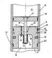
- the single figure partially shows a basic and not to scale representation a longitudinal section through the piston accumulator.
- the piston accumulator has a longitudinally displaceable inside a accumulator housing 10 first separating piston 12, which has a fluid side or oil side 14 from a Gas side 16 separates.
- the storage housing 10 is cylindrical, wherein the end caps with the gas or liquid connection are omitted for simplicity of illustration in the figure.
- the gas side 16 is generally filled with nitrogen as the working gas and hydraulic oil is stored on the fluid side 14. So between those two pressure rooms addressed a pressure level as balanced as possible there is basically a requirement that the friction between the as Whole with 18 designated sealing device and the inner wall of the storage housing 10 is very small during the piston movement. This is why usually the surface on the inside of the cylinder barrel that houses the storage case 10 forms, finely machined.
- the conventional sealing system of the accumulator consists of the usual ring or O-ring seals 20 in the outer circumferential grooves 22 on the outer circumferential side are embedded in the separating piston 12. Furthermore, the sealing device has 18 a separating agent 24 with depth filtration property, which is also in an outer circumferential groove 22 of the separating piston 12 is received.
- the release agent 24 consists of a felt, in particular in the form of a felt ring.
- the separating agent 24 has the depth filtration property as part of the sealing device 18 to the fluid side 14 arranged last and the others already mentioned parts of the sealing device 18 in the form of the ring seals 20 are in the direction of the gas side 16 and away from the fluid side 14 on the outer peripheral side arranged on the separating piston 12.
- a guide belt 26 is arranged in a conventional design, which is not shown for the sake of simplicity, but also from an outer circumferential groove 22 of the separating piston 12 is received.
- the separating piston 12 is in the manner of a cylindrical piston with a central cylindrical one Inner recess 28 formed, which opens to the gas side 16 and one Represents part of the same ..
- Second separating piston 30 in addition to the first separating piston 12 arranged, one arranged between these two separating pistons 12,30 Intermediate space 32 can be filled with a sealing medium.
- the sealing medium which is usually a highly viscous oil, is under the influence of the two separating pistons 12, 30, which are preloaded via an energy accumulator 34 are kept movable towards each other.
- the two separating pistons 12, 30 are from passed through a connecting rod 36 and as a force accumulator 34 is a compression spring provided that has one end at the bottom 38 within the inner recess 28 of the first separating piston 12 is supported and with the other end the compression spring is supported on a fixed annular holding plate 40 on upper free end of the connecting rod 36.
- the sealing medium can also consist of a separation gas or a working fluid, as it is on the Fluid side 14 is used.
- the two have Separating pistons 12, 30 each have an annular groove 42 which does not accommodate two sealing rings shown serve to space 32 relative to the Seal the fluid side 14 and the gas side 16 in the interior.
- the connecting rod 36 is, as far as it reaches through the compression spring, with this in the inner recess 28 of the first separating piston 12 guided in the middle.
- the first Separating piston 12 opposite end of the connecting rod 28 is in contrast firmly connected to the second separating piston 30.
- the supply line 44 is at the bottom 38 of the inner recess 28 of the first separating piston 12 a longitudinal channel arranged parallel to the longitudinal axis of the connecting rod 36 runs.
- the feed line 44 points in the area of the bottom 38 on a grease nipple 46, via which and via the feed line 44 the highly viscous sealing medium can be pressed into the intermediate space 32.
- the injection pressure is chosen such that the resulting in the space 32 Oil pressure caused by the preload of the braced against each other Separating piston 12.30 is higher than an achievable in the operation of this piston accumulator Pressure on the gas side 16 or the fluid side 14.
Landscapes
- Engineering & Computer Science (AREA)
- Physics & Mathematics (AREA)
- Fluid Mechanics (AREA)
- Mechanical Engineering (AREA)
- General Engineering & Computer Science (AREA)
- Chemical & Material Sciences (AREA)
- Analytical Chemistry (AREA)
- Supply Devices, Intensifiers, Converters, And Telemotors (AREA)
- Sealing Devices (AREA)
- Fluid-Pressure Circuits (AREA)
Description
Claims (6)
- Kolbenspeicher mit einem innerhalb eines Speichergehäuses (10) längsverfahrbaren Trennkolben (12), der eine Fluidseite (14) des Speichers von seiner Gasseite (16) über eine Dichteinrichtung (18) dichtend trennt, wobei auf der Gasseite (16) des Speichers ein zweiter Trennkolben (30) angeordnet ist und wobei ein zwischen den beiden Trennkolben (12,30) angeordneter Zwischenraum (32) mit einem Dichtmittel versehen ist, das unter der Einwirkung der beiden Trennkolben (12,30) vorgespannt ist, die über einen Kraftspeicher (34) aufeinander zu bewegbar sind, dadurch gekennzeichnet, daß die Dichteinrichtung (18) ein Trennmittel (24) mit Tiefenfiltrationseigenschaft aufweist, daß das Trennmittel (24) mit der Tiefenfiltrationseigenschaft als Teil der Dichteinrichtung (18) zur Fluidseite (14) hin zuletzt angeordnet ist und die weiteren Teile der Dichteinrichtung (18) in Richtung der Gasseite (16) außenumfangsseitig am Trennkolben (12) angeordnet sind, und daß das Dichtmittel aus einem hochviskosen Dichtmedium besteht.
- Kolbenspeicher nach Anspruch 1, dadurch gekennzeichnet, daß das Trennmittel (24) aus einem Filz besteht.
- Kolbenspeicher nach Anspruch 1 oder 2, dadurch gekennzeichnet, daß die weiteren Teile der Dichteinrichtung (18) aus Gummi- oder Elastomerdichtungen (20) gebildet sind und daß zwischen den Dichtringen (20) längs des Trennkolbens (12) ein Führungsband (26) angeordnet ist, das die Längsführung des Trennkolbens (12) innerhalb des Speichergehäuses (10) unterstützt.
- Kolbenspeicher nach einem der Ansprüche 1 bis 3, dadurch gekennzeichnet, daß mindestens einer der Trennkolben (12) eine Zuführleitung und Entgasungsbohrung (44) für das Dichtmedium aufweist, die in den Zwischenraum (32) mündet.
- Kolbenspeicher nach Anspruch 3 oder 4, dadurch gekennzeichnet, daß die beiden Trennkolben (12,30) von einer Verbindungsstange (36) durchgriffen sind und daß als Kraftspeicher (34) eine Druckfeder vorgesehen ist, die sich mit einem Ende an dem ersten Trennkolben (12) und mit dem anderen Ende an der Verbindungsstange (36) abstützt.
- Kolbenspeicher nach einem der Ansprüche 1 bis 5, dadurch gekennzeichnet, daß das Dichtmedium ein hochviskoses Öl ist, das Betriebsmedium oder Gas ist.
Applications Claiming Priority (2)
| Application Number | Priority Date | Filing Date | Title |
|---|---|---|---|
| DE19740150 | 1997-09-12 | ||
| DE19740150A DE19740150A1 (de) | 1997-09-12 | 1997-09-12 | Kolbenspeicher mit Tiefenfiltrationsdichtung |
Publications (3)
| Publication Number | Publication Date |
|---|---|
| EP0902193A2 EP0902193A2 (de) | 1999-03-17 |
| EP0902193A3 EP0902193A3 (de) | 1999-07-07 |
| EP0902193B1 true EP0902193B1 (de) | 2003-10-29 |
Family
ID=7842159
Family Applications (1)
| Application Number | Title | Priority Date | Filing Date |
|---|---|---|---|
| EP98113168A Expired - Lifetime EP0902193B1 (de) | 1997-09-12 | 1998-07-15 | Kolbenspeicher mit Tiefenfiltrationsdichtung |
Country Status (6)
| Country | Link |
|---|---|
| EP (1) | EP0902193B1 (de) |
| AT (1) | ATE253177T1 (de) |
| DE (2) | DE19740150A1 (de) |
| DK (1) | DK0902193T3 (de) |
| ES (1) | ES2210626T3 (de) |
| NO (1) | NO320760B1 (de) |
Cited By (1)
| Publication number | Priority date | Publication date | Assignee | Title |
|---|---|---|---|---|
| CN103511402A (zh) * | 2012-06-18 | 2014-01-15 | 中国航空工业集团公司西安飞机设计研究所 | 一种防止液压锁闭的方法及其专用压力平衡器 |
Families Citing this family (5)
| Publication number | Priority date | Publication date | Assignee | Title |
|---|---|---|---|---|
| DE10052665B4 (de) * | 2000-10-24 | 2007-02-01 | Zf Sachs Ag | Kolbenspeicher für eine Druckmittel-Betätigungsvorrichtung |
| DE10111332B4 (de) * | 2001-03-08 | 2004-08-19 | Carl Freudenberg Kg | Kolbenspeicher |
| DE10209663C1 (de) * | 2002-03-05 | 2003-07-31 | Hydac Technology Gmbh | Druckspeicher |
| DE10242104A1 (de) * | 2002-03-06 | 2003-09-18 | Continental Teves Ag & Co Ohg | Kolbenspeicher |
| RU2252148C1 (ru) * | 2003-12-05 | 2005-05-20 | Федеральное государственное образовательное учреждение высшего профессионального образования "Азово-Черноморская государственная агроинженерная академия" (ФГОУ ВПО АЧГАА) | Устройство для снижения жесткости трансмиссии машинотракторных агрегатов |
Family Cites Families (6)
| Publication number | Priority date | Publication date | Assignee | Title |
|---|---|---|---|---|
| DE2019407B2 (de) * | 1970-04-22 | 1975-07-10 | Hydrotechnik Gmbh, 6051 Laemmerspiel | Trennkolben fuer hydropneumatische Energiespeicher |
| CH591020A5 (en) * | 1975-08-15 | 1977-08-31 | Gfeller Hans | High pressure storage reservoir - has separator of two longitudinally displaceable pistons |
| SE447296B (sv) * | 1985-11-25 | 1986-11-03 | Stromsholmens Mek Verkstad | Avstrykaranordning vid cylinder och axiellt rorlig kolv |
| DE3619990A1 (de) * | 1986-06-13 | 1987-12-17 | Bosch Gmbh Robert | Kolbendruckspeicher |
| SE459275B (sv) * | 1987-10-23 | 1989-06-19 | Volvo Flygmotor Ab | Anordning foer oskadliggoerande av metallspaanor i en tryckvaetskeackumulator |
| DE4141929A1 (de) * | 1991-12-19 | 1993-06-24 | Bosch Gmbh Robert | Kolbenspeicher |
-
1997
- 1997-09-12 DE DE19740150A patent/DE19740150A1/de not_active Withdrawn
-
1998
- 1998-07-15 ES ES98113168T patent/ES2210626T3/es not_active Expired - Lifetime
- 1998-07-15 EP EP98113168A patent/EP0902193B1/de not_active Expired - Lifetime
- 1998-07-15 DK DK98113168T patent/DK0902193T3/da active
- 1998-07-15 AT AT98113168T patent/ATE253177T1/de not_active IP Right Cessation
- 1998-07-15 DE DE59810011T patent/DE59810011D1/de not_active Expired - Fee Related
- 1998-09-11 NO NO19984186A patent/NO320760B1/no unknown
Cited By (1)
| Publication number | Priority date | Publication date | Assignee | Title |
|---|---|---|---|---|
| CN103511402A (zh) * | 2012-06-18 | 2014-01-15 | 中国航空工业集团公司西安飞机设计研究所 | 一种防止液压锁闭的方法及其专用压力平衡器 |
Also Published As
| Publication number | Publication date |
|---|---|
| NO984186D0 (no) | 1998-09-11 |
| ATE253177T1 (de) | 2003-11-15 |
| DE59810011D1 (de) | 2003-12-04 |
| NO320760B1 (no) | 2006-01-23 |
| DE19740150A1 (de) | 1999-03-25 |
| DK0902193T3 (da) | 2004-02-23 |
| ES2210626T3 (es) | 2004-07-01 |
| NO984186L (no) | 1999-03-15 |
| EP0902193A2 (de) | 1999-03-17 |
| EP0902193A3 (de) | 1999-07-07 |
Similar Documents
| Publication | Publication Date | Title |
|---|---|---|
| DE2759943C2 (de) | Dichtungsanordnung für die Kolbenstange eines Stoßdämpfers | |
| EP1552162B1 (de) | Hydrospeicher | |
| DE10033871B4 (de) | Druckabhängig reagierendes Ventil, insbesondere für einen Schwingungsdämpfer | |
| DE1057403B (de) | Abschlussdeckel fuer Zylinder, insbesondere von hydraulischen Stossdaempfern, mit dichter Kolbenstangendurchfuehrung | |
| DE112010005137T5 (de) | Hydraulischer Stoßdämpfer | |
| DE102015008987A1 (de) | Stoßdämpfer und dessen Verwendung | |
| EP0902193B1 (de) | Kolbenspeicher mit Tiefenfiltrationsdichtung | |
| EP0040810B1 (de) | Reibungsfeder | |
| EP0202502B1 (de) | Druckspeicher mit einer ersten und einer zweiten Kammer | |
| EP1342922B1 (de) | Druckspeicher | |
| DE10314962A1 (de) | Dichtung für eine Betätigungseinrichtung | |
| EP0854296B1 (de) | Kolbenspeicher mit Dichtungsvorrichtung | |
| DE10323299A1 (de) | Dichtungsanordnung an Kolbenstangen | |
| DE3434011C2 (de) | ||
| DE2336118A1 (de) | Einrichtung zur hydraulik-kolbenabdichtung, insbesondere bei hochdruckkolbenpumpen | |
| EP1544521A1 (de) | Dichtring zur Abdichtung von Flüssigkeiten | |
| DE19936462B4 (de) | Abstreifring | |
| DE102014218992A1 (de) | Kraftstoffhochdruckpumpe | |
| DE102018105913A1 (de) | Dichtring | |
| DE10111332B4 (de) | Kolbenspeicher | |
| DE102007031292A1 (de) | Hydraulisch-mechanische Spannvorrichtung für einen Zugmitteltrieb | |
| DE20102031U1 (de) | Trennzylinder | |
| EP4370802B1 (de) | Hydrospeicher | |
| DE29909294U1 (de) | Gasfeder | |
| DE2019407B2 (de) | Trennkolben fuer hydropneumatische Energiespeicher |
Legal Events
| Date | Code | Title | Description |
|---|---|---|---|
| PUAI | Public reference made under article 153(3) epc to a published international application that has entered the european phase |
Free format text: ORIGINAL CODE: 0009012 |
|
| AK | Designated contracting states |
Kind code of ref document: A2 Designated state(s): AT BE CH DE DK ES FR GB IT LI NL SE |
|
| AX | Request for extension of the european patent |
Free format text: AL;LT;LV;MK;RO;SI |
|
| PUAL | Search report despatched |
Free format text: ORIGINAL CODE: 0009013 |
|
| AK | Designated contracting states |
Kind code of ref document: A3 Designated state(s): AT BE CH CY DE DK ES FI FR GB GR IE IT LI LU MC NL PT SE |
|
| AX | Request for extension of the european patent |
Free format text: AL;LT;LV;MK;RO;SI |
|
| 17P | Request for examination filed |
Effective date: 19990824 |
|
| AKX | Designation fees paid |
Free format text: AT BE CH DE DK ES FR GB IT LI NL SE |
|
| 17Q | First examination report despatched |
Effective date: 20020122 |
|
| GRAH | Despatch of communication of intention to grant a patent |
Free format text: ORIGINAL CODE: EPIDOS IGRA |
|
| GRAS | Grant fee paid |
Free format text: ORIGINAL CODE: EPIDOSNIGR3 |
|
| GRAA | (expected) grant |
Free format text: ORIGINAL CODE: 0009210 |
|
| AK | Designated contracting states |
Kind code of ref document: B1 Designated state(s): AT BE CH DE DK ES FR GB IT LI NL SE |
|
| REG | Reference to a national code |
Ref country code: GB Ref legal event code: FG4D Free format text: NOT ENGLISH |
|
| REG | Reference to a national code |
Ref country code: CH Ref legal event code: NV Representative=s name: ISLER & PEDRAZZINI AG Ref country code: CH Ref legal event code: EP |
|
| GBT | Gb: translation of ep patent filed (gb section 77(6)(a)/1977) |
Effective date: 20031029 |
|
| REG | Reference to a national code |
Ref country code: SE Ref legal event code: TRGR |
|
| REF | Corresponds to: |
Ref document number: 59810011 Country of ref document: DE Date of ref document: 20031204 Kind code of ref document: P |
|
| REG | Reference to a national code |
Ref country code: DK Ref legal event code: T3 |
|
| ET | Fr: translation filed | ||
| REG | Reference to a national code |
Ref country code: ES Ref legal event code: FG2A Ref document number: 2210626 Country of ref document: ES Kind code of ref document: T3 |
|
| PG25 | Lapsed in a contracting state [announced via postgrant information from national office to epo] |
Ref country code: GB Free format text: LAPSE BECAUSE OF NON-PAYMENT OF DUE FEES Effective date: 20040715 |
|
| PGFP | Annual fee paid to national office [announced via postgrant information from national office to epo] |
Ref country code: DK Payment date: 20040715 Year of fee payment: 7 |
|
| PG25 | Lapsed in a contracting state [announced via postgrant information from national office to epo] |
Ref country code: SE Free format text: LAPSE BECAUSE OF NON-PAYMENT OF DUE FEES Effective date: 20040716 Ref country code: ES Free format text: LAPSE BECAUSE OF NON-PAYMENT OF DUE FEES Effective date: 20040716 |
|
| PGFP | Annual fee paid to national office [announced via postgrant information from national office to epo] |
Ref country code: CH Payment date: 20040721 Year of fee payment: 7 |
|
| PGFP | Annual fee paid to national office [announced via postgrant information from national office to epo] |
Ref country code: NL Payment date: 20040729 Year of fee payment: 7 |
|
| PG25 | Lapsed in a contracting state [announced via postgrant information from national office to epo] |
Ref country code: BE Free format text: LAPSE BECAUSE OF NON-PAYMENT OF DUE FEES Effective date: 20040731 |
|
| PLBE | No opposition filed within time limit |
Free format text: ORIGINAL CODE: 0009261 |
|
| STAA | Information on the status of an ep patent application or granted ep patent |
Free format text: STATUS: NO OPPOSITION FILED WITHIN TIME LIMIT |
|
| 26N | No opposition filed |
Effective date: 20040730 |
|
| BERE | Be: lapsed |
Owner name: *HYDAC TECHNOLOGY G.M.B.H. Effective date: 20040731 |
|
| EUG | Se: european patent has lapsed | ||
| GBPC | Gb: european patent ceased through non-payment of renewal fee |
Effective date: 20040715 |
|
| PG25 | Lapsed in a contracting state [announced via postgrant information from national office to epo] |
Ref country code: FR Free format text: LAPSE BECAUSE OF NON-PAYMENT OF DUE FEES Effective date: 20050331 |
|
| REG | Reference to a national code |
Ref country code: FR Ref legal event code: ST |
|
| PGFP | Annual fee paid to national office [announced via postgrant information from national office to epo] |
Ref country code: DE Payment date: 20050701 Year of fee payment: 8 |
|
| PG25 | Lapsed in a contracting state [announced via postgrant information from national office to epo] |
Ref country code: IT Free format text: LAPSE BECAUSE OF NON-PAYMENT OF DUE FEES Effective date: 20050715 |
|
| PGFP | Annual fee paid to national office [announced via postgrant information from national office to epo] |
Ref country code: AT Payment date: 20050728 Year of fee payment: 8 |
|
| PG25 | Lapsed in a contracting state [announced via postgrant information from national office to epo] |
Ref country code: LI Free format text: LAPSE BECAUSE OF NON-PAYMENT OF DUE FEES Effective date: 20050731 Ref country code: CH Free format text: LAPSE BECAUSE OF NON-PAYMENT OF DUE FEES Effective date: 20050731 |
|
| PG25 | Lapsed in a contracting state [announced via postgrant information from national office to epo] |
Ref country code: DK Free format text: LAPSE BECAUSE OF NON-PAYMENT OF DUE FEES Effective date: 20050801 |
|
| REG | Reference to a national code |
Ref country code: ES Ref legal event code: FD2A Effective date: 20040716 |
|
| PG25 | Lapsed in a contracting state [announced via postgrant information from national office to epo] |
Ref country code: NL Free format text: LAPSE BECAUSE OF NON-PAYMENT OF DUE FEES Effective date: 20060201 |
|
| REG | Reference to a national code |
Ref country code: CH Ref legal event code: PL |
|
| NLV4 | Nl: lapsed or anulled due to non-payment of the annual fee |
Effective date: 20060201 |
|
| REG | Reference to a national code |
Ref country code: DK Ref legal event code: EBP |
|
| PG25 | Lapsed in a contracting state [announced via postgrant information from national office to epo] |
Ref country code: AT Free format text: LAPSE BECAUSE OF NON-PAYMENT OF DUE FEES Effective date: 20060715 |
|
| PG25 | Lapsed in a contracting state [announced via postgrant information from national office to epo] |
Ref country code: DE Free format text: LAPSE BECAUSE OF NON-PAYMENT OF DUE FEES Effective date: 20070201 |
|
| BERE | Be: lapsed |
Owner name: *HYDAC TECHNOLOGY G.M.B.H. Effective date: 20040731 |