EP0902246A2 - Procédé de fonctionnement d'une tour de refroidissement sèche / humide - Google Patents
Procédé de fonctionnement d'une tour de refroidissement sèche / humide Download PDFInfo
- Publication number
- EP0902246A2 EP0902246A2 EP98810858A EP98810858A EP0902246A2 EP 0902246 A2 EP0902246 A2 EP 0902246A2 EP 98810858 A EP98810858 A EP 98810858A EP 98810858 A EP98810858 A EP 98810858A EP 0902246 A2 EP0902246 A2 EP 0902246A2
- Authority
- EP
- European Patent Office
- Prior art keywords
- mass flow
- wet
- cooling water
- dry
- water
- Prior art date
- Legal status (The legal status is an assumption and is not a legal conclusion. Google has not performed a legal analysis and makes no representation as to the accuracy of the status listed.)
- Granted
Links
- 238000001816 cooling Methods 0.000 title claims abstract description 79
- 238000011017 operating method Methods 0.000 title 1
- 239000000498 cooling water Substances 0.000 claims abstract description 56
- XLYOFNOQVPJJNP-UHFFFAOYSA-N water Substances O XLYOFNOQVPJJNP-UHFFFAOYSA-N 0.000 claims description 25
- 238000000034 method Methods 0.000 claims description 14
- 238000001035 drying Methods 0.000 claims description 8
- 239000000203 mixture Substances 0.000 claims description 5
- 238000002156 mixing Methods 0.000 claims description 2
- 239000003570 air Substances 0.000 description 27
- 238000001704 evaporation Methods 0.000 description 6
- 230000008020 evaporation Effects 0.000 description 6
- 239000012080 ambient air Substances 0.000 description 3
- 230000007423 decrease Effects 0.000 description 3
- 230000017525 heat dissipation Effects 0.000 description 3
- 238000010586 diagram Methods 0.000 description 2
- 238000010792 warming Methods 0.000 description 2
- 239000003990 capacitor Substances 0.000 description 1
- 230000001413 cellular effect Effects 0.000 description 1
- 238000010276 construction Methods 0.000 description 1
- 238000005265 energy consumption Methods 0.000 description 1
- 238000007710 freezing Methods 0.000 description 1
- 230000008014 freezing Effects 0.000 description 1
- 239000007921 spray Substances 0.000 description 1
Images


Classifications
-
- F—MECHANICAL ENGINEERING; LIGHTING; HEATING; WEAPONS; BLASTING
- F28—HEAT EXCHANGE IN GENERAL
- F28C—HEAT-EXCHANGE APPARATUS, NOT PROVIDED FOR IN ANOTHER SUBCLASS, IN WHICH THE HEAT-EXCHANGE MEDIA COME INTO DIRECT CONTACT WITHOUT CHEMICAL INTERACTION
- F28C1/00—Direct-contact trickle coolers, e.g. cooling towers
- F28C1/14—Direct-contact trickle coolers, e.g. cooling towers comprising also a non-direct contact heat exchange
-
- F—MECHANICAL ENGINEERING; LIGHTING; HEATING; WEAPONS; BLASTING
- F28—HEAT EXCHANGE IN GENERAL
- F28F—DETAILS OF HEAT-EXCHANGE AND HEAT-TRANSFER APPARATUS, OF GENERAL APPLICATION
- F28F27/00—Control arrangements or safety devices specially adapted for heat-exchange or heat-transfer apparatus
- F28F27/003—Control arrangements or safety devices specially adapted for heat-exchange or heat-transfer apparatus specially adapted for cooling towers
-
- Y—GENERAL TAGGING OF NEW TECHNOLOGICAL DEVELOPMENTS; GENERAL TAGGING OF CROSS-SECTIONAL TECHNOLOGIES SPANNING OVER SEVERAL SECTIONS OF THE IPC; TECHNICAL SUBJECTS COVERED BY FORMER USPC CROSS-REFERENCE ART COLLECTIONS [XRACs] AND DIGESTS
- Y02—TECHNOLOGIES OR APPLICATIONS FOR MITIGATION OR ADAPTATION AGAINST CLIMATE CHANGE
- Y02B—CLIMATE CHANGE MITIGATION TECHNOLOGIES RELATED TO BUILDINGS, e.g. HOUSING, HOUSE APPLIANCES OR RELATED END-USER APPLICATIONS
- Y02B30/00—Energy efficient heating, ventilation or air conditioning [HVAC]
- Y02B30/70—Efficient control or regulation technologies, e.g. for control of refrigerant flow, motor or heating
Definitions
- the invention relates to a method of operating a particular load predefined climatic boundary conditions designed wet-dry cooling tower with at least partially water-side series connection of Dry part and wet part, i.e. with pure series connection or combined series and parallel connection, with operating conditions deviating from this design load, especially in the case of steam turbine bypass, overload and part-load operation, in order to maintain freedom from swaths.
- Wet-dry cooling towers also known as hybrid cooling towers, are used in energy supply companies primarily used to get in one if possible wide load range and under typical climatic conditions, with the exception extreme climatic situations, visible cooling tower swaths, i.e. for the environment Ejection of droplets, freezing rain and surface icing as well as shading each according to the swath dimension and spread.
- visible cooling tower swaths i.e. for the environment Ejection of droplets, freezing rain and surface icing as well as shading each according to the swath dimension and spread.
- the cooling tower manufacturer designs the mix so that supersaturated cooling air of the wet part with heated, i.e. dried cooling air of the Dry parts when leaving the cooling tower and the mixture with the ambient air there are no visible exhaust vapors.
- the relationship from heat dissipation in the dry section to heat dissipation in the wet section about 1: 5.
- DE 195 21 814 C1 describes a method for controlling the air quantity ratio known a wet-dry cooling tower, with which the energy consumption for the generation of the cooling air flow acted upon by the dry part Amount of energy is limited, which in the respective operating state Compliance with freedom from steam is required.
- the procedure is marked by measuring the temperature and relative humidity of the ambient air and the temperature of the exhaust air of both the dry section and the wet section as Parameters of the respective operating state, by determining the required Ratio of the air volume flows on the one hand of the wet part and on the other hand of the dry part based on these parameters with the specification of less than 100% relative Humidity limit and by controlling the determined Air throughput through the dry section while maintaining that for each Cooling power required air flow through the wet part.
- the cooling tower suppliers therefore use the current state of the art for security the hybrid cooling towers with predetermined climatic conditions and cooling water side conditions to a nominal load at which a defined maximum heat emission (e.g. overload, steam turbine bypass).
- a defined maximum heat emission e.g. overload, steam turbine bypass
- the invention tries to avoid these disadvantages. It is based on the task a simple method of operating on a specific load predefined climatic boundary conditions designed wet-dry cooling tower to create with that even under operating conditions that are affected by the operation Design conditions differ, freedom from steam is achieved without the dry section must be designed for the maximum load.
- the invention With increased heat load in the condenser (steam turbine bypass operation and overload mode) the temperature of the cooling water entering the cooling tower increases (Hot water temperature).
- the invention now makes humidification advantageous reduced in the wet section of the cooling tower and thereby evaporation reduced, resulting in an increase in cold water temperature at the cooling tower outlet leads.
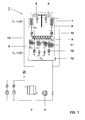
- Fig. 1 shows in a cross section schematically the structure of a cooling air side parallel wet-dry cooling tower connected on the water side.
- Cooling tower is designed for a rated operation, which is based on 100% steam turbine load with given climatic conditions.
- the wet-dry cooling tower is integrated in a combined power plant, not shown. 1 shows, in addition to the cooling tower, only the condenser 2 integrated in the cooling water circuit and the cooling water pump 3.
- the cooling tower has a circular cylindrical cooling tower outlet 4, in which a fan 5, which generates the entire train in the cooling tower, is arranged.
- the wet part 6 of the cooling tower consists of trickle internals, to which the water W T to be cooled, which was previously fed to the dry part 7 via a riser 13, was drained off via this and subsequently fed via a line 8 to a distribution device 9 (spray platform) via the distribution device 9 is abandoned from above.
- the trickle internals are subjected to a cooling air flow K N from below in counterflow to the cooling water W N.
- the cooled water W N dripping from the wet part 6 collects in a basin 10 at the bottom of the cooling tower, from which it is then fed again to the power plant cycle.
- the dry part 7 is formed from heat exchangers and is located above the distribution device 9 for the wet part 6.
- the cooling air flow K T sucked in by the fan 5 mixes with the cooling air flow K N , which was previously passed through a droplet separator, not shown. The heated air is then discharged into the atmosphere at the cooling tower outlet.
- cooling water mass flow W T is derived of the cooling tower over the drying part 7, while the derived via the wet part 6 of cooling water mass flow W N in comparison with the rated load operation by means of a cooling water bypass mass flow W is reduced B, wherein the size of the bypass mass flow W B in Dependence on the respective specific operating conditions is selected.
- a bypass line 11 for the cooling water bypass mass flow W B branches off from the line 8, ie between the dry part 7 and the wet part 6.
- valves 12 are arranged in the lines 8, 11, 13 and can be operated manually or by motor. In an extreme case, the bypass water mass flow W B can correspond to the complete cooling water flow.
- the cooling tower is a fixed point wet-dry cooling tower which is supplied with a constant amount of air. In this embodiment, it consists of 5 cells.
- the cooling water mass flow is 4.2 m 3 / s, the cold water temperature is> 15 ° C.
- A is the guarantee point for freedom from steam (6 ° C ambient temperature and 85% relative air humidity), and B is the switchover point at which the cooling water flow via the wet section must be reduced.
- Fig. 3 shows a further embodiment of the invention.
- the wet-dry cooling tower differs from the exemplary embodiment according to FIG. 1 only in that the drying section 7 and the wet section 6 are no longer connected purely in series, but instead a pipe (branch 14) branches off from the riser pipe 13, via which one Part of the cooling water (cooling water mass flow W N ,) is led past the drying part 7.
- a pipe branches off from the riser pipe 13, via which one Part of the cooling water (cooling water mass flow W N ,) is led past the drying part 7.
- 40% of the total cooling water is provided for the dry part 7 and 60% directly for the wet part 6.
- the partial flow W T which has run off the dry part 7 is mixed with the branched partial flow W N , and then supplied together as W N to the wet part 6.
- the cooling water-side mode of operation according to the invention is again selected by partially bypassing the wet part 6.
- a certain proportion W B is branched off beforehand from the water flow W T coming from the dry part 7, which is fed via the line 8 to the distribution device 9 and thus to the wet part 6, and discharged past the wet part 6 via the line 11.
- the cooling water mass flow W N via the line 14 is mixed with the remaining partial flow W T coming from the drying section 7 and then sprayed via the distribution device 9.
- this mode of operation reduces the evaporation due to the reduced loading in the wet part (compared to operation at 100% steam turbine load), so that freedom from steam can be guaranteed both in the overload mode of operation and in the steam turbine bypass and part-load operation.
- the bypass line 11 does not branch off from the line 8 here, but from the line 14 in which the still uncooled cooling water mass flow W N 'flows. ie the bypass water mass flow W B has a higher temperature in comparison to the exemplary embodiment shown in FIG. 3 and thus this intervention on the cooling water side is more effective than in FIG. 3.
- FIG. 5 finally shows an embodiment variant of the invention, in which, in contrast to FIG. 4, the cooling water bypass mass flow W B is only removed after the two flows W N 'and W T have been mixed. Which of the possible variants is used depends on the respective specific conditions.
- Another embodiment relates to the operation of a cooling tower, which is designed for a load greater than the nominal load (100% steam turbine load), but is significantly smaller than the maximum load, so the dry part 7 is somewhat enlarged, for example by 25% compared to an interpretation to nominal load.
- the cooling water passed through the dry section 7 and the wet section 6 is and in partial load operation, the cooling water is passed only through the dry part 7 becomes.
- freedom from steam can be achieved even under these operating conditions become. Even in this case, will still be compared to the previous one usual design of the cooling tower for maximum load considerable investment costs saved.
- the invention is not limited to the exemplary embodiments shown here.
- the invention is of course also applicable to cooling towers with an air-side series connection.
- the invention can also be combined in partial load operation with a reduction in the water mass flow entering the cooling tower or a reduction in the water mass flow entering the cooling tower with simultaneous switching off of a certain number of cells and possibly an additional reduction in the air mass flow.
- Cooling tower cell 2nd capacitor 3rd Cooling water pump 4th Cooling tower outlet 5 fan 6 Wet part 7 Dry section 8th Water pipe between items 7 and 9 9 Distribution device 10th Pool 1 1 Bypass line 12th Valves 13 Riser pipe 14 Junction W N Cooling water mass flow wet part (total) W N , Cooling water mass flow wet part (direct) W T Cooling water mass flow dry part W B Cooling water bypass mass flow wet part K N Cooling air flow wet part K T Cooling air flow dry part T U Ambient temperature ⁇ humidity A Guarantee point for freedom from steam B Switchover point
Landscapes
- Engineering & Computer Science (AREA)
- Mechanical Engineering (AREA)
- General Engineering & Computer Science (AREA)
- Physics & Mathematics (AREA)
- Thermal Sciences (AREA)
- Control Of Turbines (AREA)
- Turbine Rotor Nozzle Sealing (AREA)
Applications Claiming Priority (2)
| Application Number | Priority Date | Filing Date | Title |
|---|---|---|---|
| DE19739726 | 1997-09-11 | ||
| DE19739726A DE19739726A1 (de) | 1997-09-11 | 1997-09-11 | Verfahren zum Betrieb eines Nass-Trocken-Kühlturmes |
Publications (3)
| Publication Number | Publication Date |
|---|---|
| EP0902246A2 true EP0902246A2 (fr) | 1999-03-17 |
| EP0902246A3 EP0902246A3 (fr) | 2000-04-12 |
| EP0902246B1 EP0902246B1 (fr) | 2002-10-16 |
Family
ID=7841866
Family Applications (1)
| Application Number | Title | Priority Date | Filing Date |
|---|---|---|---|
| EP98810858A Expired - Lifetime EP0902246B1 (fr) | 1997-09-11 | 1998-08-31 | Procédé de fonctionnement d'une tour de refroidissement sèche / humide |
Country Status (2)
| Country | Link |
|---|---|
| EP (1) | EP0902246B1 (fr) |
| DE (2) | DE19739726A1 (fr) |
Cited By (1)
| Publication number | Priority date | Publication date | Assignee | Title |
|---|---|---|---|---|
| CN119983914A (zh) * | 2025-01-14 | 2025-05-13 | 合肥工业大学 | 一种基于边云协同计算的中央空调冷却塔控制方法 |
Families Citing this family (1)
| Publication number | Priority date | Publication date | Assignee | Title |
|---|---|---|---|---|
| DE102007036343B4 (de) * | 2007-08-02 | 2009-12-31 | Enbw Kraftwerke Ag | Verfahren und Kühlvorrichtung für Dampfkraftwerke mit einem Nasskühlturm |
Citations (1)
| Publication number | Priority date | Publication date | Assignee | Title |
|---|---|---|---|---|
| DE19521814C1 (de) | 1995-06-16 | 1996-11-21 | Balcke Duerr Ag | Verfahren zur Steuerung des Luftmengenverhältnisses eines Naß-Trocken-Kühlturms |
Family Cites Families (3)
| Publication number | Priority date | Publication date | Assignee | Title |
|---|---|---|---|---|
| DE1812111A1 (de) * | 1968-12-02 | 1970-06-11 | Eisner Dipl Ing Joachim H | Kuehler mit Einrichtungen zur Verhinderung von Nebel- und Eisbildung und zum Betrieb mit indirektem Kreislauf |
| US3865911A (en) * | 1973-05-03 | 1975-02-11 | Res Cottrel Inc | Cooling tower type waste heat extraction method and apparatus |
| DE4442804C2 (de) * | 1994-12-01 | 1996-12-05 | Balcke Duerr Ag | Verfahren und Vorrichtung zur Wiederinbetriebnahme eines von mindestens zwei parallel zueinander geschalteten Wärmetauschern |
-
1997
- 1997-09-11 DE DE19739726A patent/DE19739726A1/de not_active Withdrawn
-
1998
- 1998-08-31 DE DE59805952T patent/DE59805952D1/de not_active Expired - Lifetime
- 1998-08-31 EP EP98810858A patent/EP0902246B1/fr not_active Expired - Lifetime
Patent Citations (1)
| Publication number | Priority date | Publication date | Assignee | Title |
|---|---|---|---|---|
| DE19521814C1 (de) | 1995-06-16 | 1996-11-21 | Balcke Duerr Ag | Verfahren zur Steuerung des Luftmengenverhältnisses eines Naß-Trocken-Kühlturms |
Non-Patent Citations (1)
| Title |
|---|
| A.STRENG: "KOMBINIERTE NASS-/TROCKENKÜHLTÜRME IN ZELLENBAUWEISE", BWK, no. 5, 1 January 1995 (1995-01-01), pages 218-224 |
Cited By (2)
| Publication number | Priority date | Publication date | Assignee | Title |
|---|---|---|---|---|
| CN119983914A (zh) * | 2025-01-14 | 2025-05-13 | 合肥工业大学 | 一种基于边云协同计算的中央空调冷却塔控制方法 |
| CN119983914B (zh) * | 2025-01-14 | 2025-10-31 | 合肥工业大学 | 一种基于边云协同计算的中央空调冷却塔控制方法 |
Also Published As
| Publication number | Publication date |
|---|---|
| EP0902246A3 (fr) | 2000-04-12 |
| EP0902246B1 (fr) | 2002-10-16 |
| DE59805952D1 (de) | 2002-11-21 |
| DE19739726A1 (de) | 1999-03-18 |
Similar Documents
| Publication | Publication Date | Title |
|---|---|---|
| DE69604120T2 (de) | Vorkühlungswärmetauscher, integriert mit stromlinienförmiger Befestigungsvorrichtung einer Gasturbine | |
| DE68908262T2 (de) | Kühlanlage zum Kondensieren von Turbinenabdampf, insbesondere für Kraftwerke. | |
| DE19633190B4 (de) | Kühlsystem für eine Brennkraftmaschine | |
| DE10154595A1 (de) | Kühlvorrichtung für ein Fahrzeug mit durch eine Brennstoffzelle gespeistem Elektromotor | |
| CH705181A1 (de) | Verfahren zum Kühlen einer Gasturbinenanlage sowie Gasturbinenanlage zur Durchführung des Verfahrens. | |
| DE3101098A1 (de) | "verfahren zum betreiben einer kombinierten gasturbinen-dampfturbinen-kraftanlage mit verbesserter steuerung der no(pfeil abwaerts)x(pfeil abwaerts)-emissionen und verbesserte gasturbinen-dampfturbinen-kraftanlage" | |
| EP0761944A1 (fr) | Méthode d'opération pour une centrale à turbine à gaz | |
| WO1996031694A1 (fr) | Procede et circuit permettant de faire fonctionner des accumulateurs de chaleur, notamment de chaleur sensible | |
| DE19961825A1 (de) | Kühl-Heiz-Kreis mit zwei Kühlern | |
| DE102010036888A1 (de) | System zur Aufbereitung des in eine Turbomaschine eintretenden Luftstroms | |
| EP1472106B1 (fr) | Installation de climatisation ayant une fonction chauffage et son mode de fonctionnement | |
| DE102016122252B4 (de) | Integrierte kraftanlage mit wärmepumpe und brennstoffzelle | |
| DE10107875A1 (de) | System zur Kühlung einer Brennstoffzellenanlage | |
| DE2602485B2 (de) | Wasserrückkühlvorrichtung | |
| DE102009051429A1 (de) | Kühllufttrockner | |
| EP0748998B1 (fr) | Procédé de contrôle du rapport des débits d'air dans une tour de refroidissement humide-sèche | |
| DE19818030A1 (de) | Verfahren und Vorrichtung zum Betreiben eines Kühlmittelkreises einer Brennkraftmaschine | |
| DE102006005176A1 (de) | Kühlkreislauf und Verfahren zur Kühlung eines Brennstoffzellenstapels | |
| DE3214855C2 (fr) | ||
| EP0902246B1 (fr) | Procédé de fonctionnement d'une tour de refroidissement sèche / humide | |
| DE2812237A1 (de) | Gasturbinenanlage | |
| DE19849619A1 (de) | Kühlsystem für ein Kraftfahrzeug | |
| DE19739725B4 (de) | Verfahren zum Betrieb eines Nass-Trocken-Kühlturmes | |
| EP0902247B1 (fr) | Procédé de fonctionnement d'une tour de refroidissement sèche / humide | |
| DE4442936A1 (de) | Gasturbine |
Legal Events
| Date | Code | Title | Description |
|---|---|---|---|
| PUAI | Public reference made under article 153(3) epc to a published international application that has entered the european phase |
Free format text: ORIGINAL CODE: 0009012 |
|
| AK | Designated contracting states |
Kind code of ref document: A2 Designated state(s): DE GB |
|
| AX | Request for extension of the european patent |
Free format text: AL;LT;LV;MK;RO;SI |
|
| PUAL | Search report despatched |
Free format text: ORIGINAL CODE: 0009013 |
|
| AK | Designated contracting states |
Kind code of ref document: A3 Designated state(s): AT BE CH CY DE DK ES FI FR GB GR IE IT LI LU MC NL PT SE |
|
| AX | Request for extension of the european patent |
Free format text: AL;LT;LV;MK;RO;SI |
|
| 17P | Request for examination filed |
Effective date: 20000925 |
|
| RAP1 | Party data changed (applicant data changed or rights of an application transferred) |
Owner name: ABB (SCHWEIZ) AG |
|
| AKX | Designation fees paid |
Free format text: DE GB |
|
| GRAG | Despatch of communication of intention to grant |
Free format text: ORIGINAL CODE: EPIDOS AGRA |
|
| RAP1 | Party data changed (applicant data changed or rights of an application transferred) |
Owner name: ALSTOM |
|
| 17Q | First examination report despatched |
Effective date: 20011203 |
|
| GRAG | Despatch of communication of intention to grant |
Free format text: ORIGINAL CODE: EPIDOS AGRA |
|
| GRAH | Despatch of communication of intention to grant a patent |
Free format text: ORIGINAL CODE: EPIDOS IGRA |
|
| GRAH | Despatch of communication of intention to grant a patent |
Free format text: ORIGINAL CODE: EPIDOS IGRA |
|
| GRAA | (expected) grant |
Free format text: ORIGINAL CODE: 0009210 |
|
| AK | Designated contracting states |
Kind code of ref document: B1 Designated state(s): DE GB |
|
| REG | Reference to a national code |
Ref country code: GB Ref legal event code: FG4D Free format text: NOT ENGLISH |
|
| REF | Corresponds to: |
Ref document number: 59805952 Country of ref document: DE Date of ref document: 20021121 |
|
| RAP2 | Party data changed (patent owner data changed or rights of a patent transferred) |
Owner name: ALSTOM (SWITZERLAND) LTD |
|
| GBT | Gb: translation of ep patent filed (gb section 77(6)(a)/1977) |
Effective date: 20030228 |
|
| REG | Reference to a national code |
Ref country code: GB Ref legal event code: 732E |
|
| PLBE | No opposition filed within time limit |
Free format text: ORIGINAL CODE: 0009261 |
|
| STAA | Information on the status of an ep patent application or granted ep patent |
Free format text: STATUS: NO OPPOSITION FILED WITHIN TIME LIMIT |
|
| 26N | No opposition filed |
Effective date: 20030717 |
|
| REG | Reference to a national code |
Ref country code: DE Ref legal event code: R082 Ref document number: 59805952 Country of ref document: DE Representative=s name: UWE ROESLER, DE |
|
| REG | Reference to a national code |
Ref country code: GB Ref legal event code: 732E Free format text: REGISTERED BETWEEN 20120802 AND 20120808 |
|
| REG | Reference to a national code |
Ref country code: DE Ref legal event code: R082 Ref document number: 59805952 Country of ref document: DE Representative=s name: RUEGER, BARTHELT & ABEL, DE Effective date: 20120713 Ref country code: DE Ref legal event code: R082 Ref document number: 59805952 Country of ref document: DE Representative=s name: ROESLER, UWE, DIPL.-PHYS.UNIV., DE Effective date: 20120713 Ref country code: DE Ref legal event code: R081 Ref document number: 59805952 Country of ref document: DE Owner name: GENERAL ELECTRIC TECHNOLOGY GMBH, CH Free format text: FORMER OWNER: ALSTOM (SWITZERLAND) LTD., BADEN, CH Effective date: 20120713 Ref country code: DE Ref legal event code: R081 Ref document number: 59805952 Country of ref document: DE Owner name: ALSTOM TECHNOLOGY LTD., CH Free format text: FORMER OWNER: ALSTOM (SWITZERLAND) LTD., BADEN, CH Effective date: 20120713 |
|
| REG | Reference to a national code |
Ref country code: DE Ref legal event code: R082 Ref document number: 59805952 Country of ref document: DE Representative=s name: RUEGER, BARTHELT & ABEL, DE |
|
| REG | Reference to a national code |
Ref country code: DE Ref legal event code: R082 Ref document number: 59805952 Country of ref document: DE Representative=s name: RUEGER, BARTHELT & ABEL, DE Ref country code: DE Ref legal event code: R081 Ref document number: 59805952 Country of ref document: DE Owner name: GENERAL ELECTRIC TECHNOLOGY GMBH, CH Free format text: FORMER OWNER: ALSTOM TECHNOLOGY LTD., BADEN, CH |
|
| PGFP | Annual fee paid to national office [announced via postgrant information from national office to epo] |
Ref country code: DE Payment date: 20160826 Year of fee payment: 19 Ref country code: GB Payment date: 20160830 Year of fee payment: 19 |
|
| REG | Reference to a national code |
Ref country code: DE Ref legal event code: R119 Ref document number: 59805952 Country of ref document: DE |
|
| GBPC | Gb: european patent ceased through non-payment of renewal fee |
Effective date: 20170831 |
|
| PG25 | Lapsed in a contracting state [announced via postgrant information from national office to epo] |
Ref country code: DE Free format text: LAPSE BECAUSE OF NON-PAYMENT OF DUE FEES Effective date: 20180301 Ref country code: GB Free format text: LAPSE BECAUSE OF NON-PAYMENT OF DUE FEES Effective date: 20170831 |