EP0902247A2 - Procédé de fonctionnement d'une tour de refroidissement sèche / humide - Google Patents
Procédé de fonctionnement d'une tour de refroidissement sèche / humide Download PDFInfo
- Publication number
- EP0902247A2 EP0902247A2 EP98810859A EP98810859A EP0902247A2 EP 0902247 A2 EP0902247 A2 EP 0902247A2 EP 98810859 A EP98810859 A EP 98810859A EP 98810859 A EP98810859 A EP 98810859A EP 0902247 A2 EP0902247 A2 EP 0902247A2
- Authority
- EP
- European Patent Office
- Prior art keywords
- cold water
- cooling tower
- wet
- cooling
- mass flow
- Prior art date
- Legal status (The legal status is an assumption and is not a legal conclusion. Google has not performed a legal analysis and makes no representation as to the accuracy of the status listed.)
- Granted
Links
- 238000001816 cooling Methods 0.000 title claims abstract description 59
- 238000011017 operating method Methods 0.000 title 1
- XLYOFNOQVPJJNP-UHFFFAOYSA-N water Substances O XLYOFNOQVPJJNP-UHFFFAOYSA-N 0.000 claims abstract description 43
- 239000000498 cooling water Substances 0.000 claims abstract description 30
- 238000000034 method Methods 0.000 claims description 9
- 239000000203 mixture Substances 0.000 claims description 6
- 239000003570 air Substances 0.000 description 20
- 241000283263 Balaenoptera edeni Species 0.000 description 3
- 239000012080 ambient air Substances 0.000 description 3
- 239000003990 capacitor Substances 0.000 description 2
- 230000001413 cellular effect Effects 0.000 description 2
- 238000010276 construction Methods 0.000 description 2
- 230000001276 controlling effect Effects 0.000 description 2
- 230000017525 heat dissipation Effects 0.000 description 2
- 238000001035 drying Methods 0.000 description 1
- 238000005265 energy consumption Methods 0.000 description 1
- 238000001704 evaporation Methods 0.000 description 1
- 230000008020 evaporation Effects 0.000 description 1
- 238000007710 freezing Methods 0.000 description 1
- 230000008014 freezing Effects 0.000 description 1
- 210000000056 organ Anatomy 0.000 description 1
- 230000003134 recirculating effect Effects 0.000 description 1
- 230000001105 regulatory effect Effects 0.000 description 1
- 239000007921 spray Substances 0.000 description 1
Images

Classifications
-
- F—MECHANICAL ENGINEERING; LIGHTING; HEATING; WEAPONS; BLASTING
- F28—HEAT EXCHANGE IN GENERAL
- F28F—DETAILS OF HEAT-EXCHANGE AND HEAT-TRANSFER APPARATUS, OF GENERAL APPLICATION
- F28F27/00—Control arrangements or safety devices specially adapted for heat-exchange or heat-transfer apparatus
- F28F27/003—Control arrangements or safety devices specially adapted for heat-exchange or heat-transfer apparatus specially adapted for cooling towers
-
- F—MECHANICAL ENGINEERING; LIGHTING; HEATING; WEAPONS; BLASTING
- F28—HEAT EXCHANGE IN GENERAL
- F28C—HEAT-EXCHANGE APPARATUS, NOT PROVIDED FOR IN ANOTHER SUBCLASS, IN WHICH THE HEAT-EXCHANGE MEDIA COME INTO DIRECT CONTACT WITHOUT CHEMICAL INTERACTION
- F28C1/00—Direct-contact trickle coolers, e.g. cooling towers
- F28C1/14—Direct-contact trickle coolers, e.g. cooling towers comprising also a non-direct contact heat exchange
-
- Y—GENERAL TAGGING OF NEW TECHNOLOGICAL DEVELOPMENTS; GENERAL TAGGING OF CROSS-SECTIONAL TECHNOLOGIES SPANNING OVER SEVERAL SECTIONS OF THE IPC; TECHNICAL SUBJECTS COVERED BY FORMER USPC CROSS-REFERENCE ART COLLECTIONS [XRACs] AND DIGESTS
- Y02—TECHNOLOGIES OR APPLICATIONS FOR MITIGATION OR ADAPTATION AGAINST CLIMATE CHANGE
- Y02B—CLIMATE CHANGE MITIGATION TECHNOLOGIES RELATED TO BUILDINGS, e.g. HOUSING, HOUSE APPLIANCES OR RELATED END-USER APPLICATIONS
- Y02B30/00—Energy efficient heating, ventilation or air conditioning [HVAC]
- Y02B30/70—Efficient control or regulation technologies, e.g. for control of refrigerant flow, motor or heating
Definitions
- the invention relates to a method for operating a specific load and wet-dry cooling tower designed for given climatic boundary conditions with at least partial series connection of dry sections and wet part in extreme weather conditions, d. H. in the event of deviations from the specified climatic boundary conditions, in order to maintain freedom from swaths.
- Wet-dry cooling towers also known as hybrid cooling towers, are used in energy supply companies primarily used to get in one if possible wide load range and under typical climatic conditions, with the exception extreme climatic situations, visible cooling tower swaths, i.e. for the environment Ejection of droplets, freezing rain and surface icing as well as shading each according to the swath dimension and spread.
- visible cooling tower swaths i.e. for the environment Ejection of droplets, freezing rain and surface icing as well as shading each according to the swath dimension and spread.
- the cooling tower manufacturer designs the mix so that supersaturated cooling air of the wet part with heated, i.e. dried cooling air of the Dry parts when leaving the cooling tower and the mixture with the ambient air there are no visible exhaust vapors.
- the relationship from heat dissipation in the dry section to heat dissipation in the wet section about 1: 5.
- DE 195 21 814 C1 describes a method for controlling the air quantity ratio known a wet-dry cooling tower, with which the energy consumption for the generation of the cooling air flow acted upon by the dry part Amount of energy is limited, which in the respective operating state Compliance with freedom from steam is required.
- the procedure is marked by measuring the temperature and relative humidity of the ambient air and the temperature of the exhaust air of both the dry section and the wet section as Parameters of the respective operating state, by determining the required Ratio of the air volume flows on the one hand of the wet part and on the other hand of the dry part based on these parameters with the specification of less than 100% relative Humidity limit and by controlling the determined Air throughput through the dry section while maintaining that for each Cooling power required air flow through the wet part.
- the invention tries to avoid these disadvantages. It is based on the task a simple method of operating on a specific load predefined climatic boundary conditions designed wet-dry cooling tower to create with which even in extreme weather conditions, d. H. also outside the swath-free climate range, as far as possible Freedom from steam can be achieved.
- this is achieved in that the extreme weather conditions Cold water pipe in the area between the pump outlet and the condenser inlet a cold water bypass mass flow is taken, which via a cold water recirculation line is led into the cooling tower, the size of the cold water bypass mass flow by operating one in the recirculation line arranged actuator is adapted to the respective conditions.
- the cold water bypass mass flow is that for the wet part envisaged cooling water mass flow before it enters the wet section and then this mixture is drained off through the wet section.
- the admixture of the cold water bypass mass flow feasible, for example the admixture in the Cooling water mass flow coming from the dry part, or the admixture of the cold water mass flow occurs in a mixture of from the dry part coming cooling water mass flow and provided directly for the wet part Cooling water mass flow.
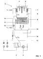
- Fig. 1 shows in a cross section schematically the structure of a cooling air side parallel wet-dry cooling tower connected on the water side.
- Cooling tower is designed for a rated operation, which is based on 100% steam turbine load with given average climatic conditions.
- the wet-dry cooling tower is integrated in a combined cycle power plant, not shown. 1 shows, in addition to the cooling tower, only the condenser 2 integrated in the cooling water circuit and the cooling water pump 3.
- the cooling tower has a circular cylindrical cooling tower outlet 4, in which a fan 5, which generates the entire train in the cooling tower, is arranged.
- the wet part 6 of the cooling tower consists of trickle internals, to which the water W T to be cooled, which was previously fed to the dry part 7 via a riser 13, was drained off via this and subsequently fed via a line 8 to a distribution device 9 (spray platform) via the distribution device 9 is abandoned from above.
- the trickle internals are subjected to a cooling air flow K N from below in counterflow to the cooling water W N.
- the cooled water W N dripping from the wet part 6 collects in a basin 10 at the bottom of the cooling tower, from which it is subsequently fed back to the power station cycle.
- the dry part 7 is formed from heat exchangers and is located above the distribution device 9 for the wet part 6.
- the cooling air flow K T sucked in by the fan 5 mixes with the cooling air flow K N , which was previously passed through a droplet separator, not shown. The heated air is then discharged into the atmosphere at the cooling tower outlet.
- a cold water recirculation line 15 is put into operation according to the invention, which from the cooling water line 16 after it has left the pump 3 or before it enters branches into the capacitor 2 and opens into the line 8.
- line 15 there is an actuator, for example a valve 12, with which the required size of the cold water bypass mass flow W BK flowing through the line can be adjusted.
- the valve 12 can be closed completely in the event of unproblematic weather conditions.
- the cold water bypass mass flow W BK is now added to the cooling water mass flow W T , which has already been passed over the dry part 7, in extreme climatic conditions before it enters the wet part 6.
- This cold water is taken from the cooling water line 16 before entering the condenser 2, ie there is a bypassing of the condenser 2.
- the amount of cooling water is reduced by the steam turbine condenser, which in turn leads to an increase in the hot water temperature (entry temperature into the cooling tower) by e.g. B. 5 ° C leads. This value is sufficient to withstand extreme weather conditions, e.g. B. tropical climate with low temperatures and high humidity in the morning, to be able to achieve freedom from steam.
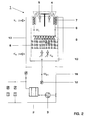
- Fig. 2 shows a second embodiment of the invention.
- the circuit differs from FIG. 1 only in that the cold water recirculation line 15, which branches off from the line 16 also after exiting the cooling water pump 3 and in which a valve 12 is also arranged, opens into the collecting basin 10.
- the size of the cold water bypass mass flow W BK which can be regulated via the organ 12, is thus conducted directly from the outlet of the pump 3 into the collecting basin.
- the outlet temperature in the condenser rises and there is no steam.
- the driving style according to the invention is not included on cooling towers a purely water-side series connection of dry section 7 and wet section 6 is limited, but it can also be used for wet-dry cooling towers with one combined series and parallel connection on the water side.
- Fig. 3 shows such an embodiment in which the cooling tower is provided with a water-side series and parallel connection of drying section 7 and wet section 6.
- a line (branch 14) branches off from the riser pipe 13, via which a part of the cooling water (cooling water mass flow W N ' ) is led past the dry part 7.
- 40% of the total cooling water is provided for the dry part 7 and 60% directly for the wet part 6.
- the partial flow W T which has run off through the dry part 7 is mixed with the branched partial flow W N ' and then supplied together as W N to the wet part 6.
- the wet part 6 is partially bypassed in order to ensure freedom from swaths.
- a certain proportion W B is branched off beforehand from the water flow W T coming from the dry part 7, which is fed via the line 8 to the distribution device 9 and thus to the wet part 6, and discharged past the wet part 6 via the line 11.
- the cooling water mass flow W N ' via the line 14 is mixed with the remaining partial flow W T coming from the dry part 7 and then sprayed via the distribution device 9.
- the bypass line 11 may also be of the line 14, in which the still uncooled the cooling water mass flow W N 'flowing along branch or line 11 branches off after the mixture of the two partial flows W N' and W T from. Which of the possible variants is used depends on the respective specific conditions.
- the cold water recirculation line 15 is put into operation by opening the valve 12 in extreme weather conditions to maintain freedom from swaths.
- the line 15 opens into the line 14 or directly into the distribution device 9.
- the cooling water mass flow to be sprayed in the wet part 6 is admixed with a cold water bypass mass flow W BK before it enters the wet part 6.
- the amount of cooling water through the steam turbine condenser is thereby reduced, which in turn leads to an increase in the hot water temperature (entry temperature into the cooling tower).
- extreme weather conditions e.g. B. tropical climate with low temperatures and high humidity in the morning, this can be achieved.
- the invention is not based on the exemplary embodiments shown here limited.
- the invention is also, for example, in the case of cooling towers with an air-side Series connection applicable, also in steam turbine power plants.
- the Cooling towers can also withstand a greater load than a nominal load of 100% Steam turbine load can be designed.
- the driving style according to the invention can also be combined with a reduction in the amount entering the cooling tower Water mass flow and, if necessary, a shutdown of a certain one Number of cells under partial load conditions, as well as an additional reduction in the air mass flow. Finally, a combined cold water recirculation both to the wet part and to the collecting container.
Landscapes
- Engineering & Computer Science (AREA)
- Mechanical Engineering (AREA)
- General Engineering & Computer Science (AREA)
- Physics & Mathematics (AREA)
- Thermal Sciences (AREA)
- Engine Equipment That Uses Special Cycles (AREA)
Applications Claiming Priority (2)
| Application Number | Priority Date | Filing Date | Title |
|---|---|---|---|
| DE19739724A DE19739724A1 (de) | 1997-09-11 | 1997-09-11 | Verfahren zum Betrieb eines Nass-Trocken-Kühlturmes |
| DE19739724 | 1997-09-11 |
Publications (3)
| Publication Number | Publication Date |
|---|---|
| EP0902247A2 true EP0902247A2 (fr) | 1999-03-17 |
| EP0902247A3 EP0902247A3 (fr) | 2000-04-12 |
| EP0902247B1 EP0902247B1 (fr) | 2002-10-16 |
Family
ID=7841864
Family Applications (1)
| Application Number | Title | Priority Date | Filing Date |
|---|---|---|---|
| EP98810859A Expired - Lifetime EP0902247B1 (fr) | 1997-09-11 | 1998-08-31 | Procédé de fonctionnement d'une tour de refroidissement sèche / humide |
Country Status (2)
| Country | Link |
|---|---|
| EP (1) | EP0902247B1 (fr) |
| DE (2) | DE19739724A1 (fr) |
Citations (1)
| Publication number | Priority date | Publication date | Assignee | Title |
|---|---|---|---|---|
| DE19521814C1 (de) | 1995-06-16 | 1996-11-21 | Balcke Duerr Ag | Verfahren zur Steuerung des Luftmengenverhältnisses eines Naß-Trocken-Kühlturms |
Family Cites Families (3)
| Publication number | Priority date | Publication date | Assignee | Title |
|---|---|---|---|---|
| US3666246A (en) * | 1970-04-07 | 1972-05-30 | Westinghouse Electric Corp | Cooling system |
| US5106543A (en) * | 1990-08-17 | 1992-04-21 | Dodds Diego E F | Apparatus and method for controlling the discharge or continuous bleed-off of cooling water and evaporative coolers |
| DE4442804C2 (de) * | 1994-12-01 | 1996-12-05 | Balcke Duerr Ag | Verfahren und Vorrichtung zur Wiederinbetriebnahme eines von mindestens zwei parallel zueinander geschalteten Wärmetauschern |
-
1997
- 1997-09-11 DE DE19739724A patent/DE19739724A1/de not_active Withdrawn
-
1998
- 1998-08-31 EP EP98810859A patent/EP0902247B1/fr not_active Expired - Lifetime
- 1998-08-31 DE DE59805953T patent/DE59805953D1/de not_active Expired - Lifetime
Patent Citations (1)
| Publication number | Priority date | Publication date | Assignee | Title |
|---|---|---|---|---|
| DE19521814C1 (de) | 1995-06-16 | 1996-11-21 | Balcke Duerr Ag | Verfahren zur Steuerung des Luftmengenverhältnisses eines Naß-Trocken-Kühlturms |
Non-Patent Citations (1)
| Title |
|---|
| A.STRENG: "KOMBINIERTE NASS-/TROCKENKÜHLTÜRME IN ZELLENBAUWEISE", BWK, no. 5, 1 January 1995 (1995-01-01), pages 218-224 |
Also Published As
| Publication number | Publication date |
|---|---|
| EP0902247B1 (fr) | 2002-10-16 |
| EP0902247A3 (fr) | 2000-04-12 |
| DE19739724A1 (de) | 1999-03-18 |
| DE59805953D1 (de) | 2002-11-21 |
Similar Documents
| Publication | Publication Date | Title |
|---|---|---|
| DE68908262T2 (de) | Kühlanlage zum Kondensieren von Turbinenabdampf, insbesondere für Kraftwerke. | |
| DE3007256C2 (fr) | ||
| CH705181A1 (de) | Verfahren zum Kühlen einer Gasturbinenanlage sowie Gasturbinenanlage zur Durchführung des Verfahrens. | |
| DE2722357A1 (de) | Klimaanlage | |
| DE2166477A1 (de) | Vorrichtung fuer die verteilung des zu kuehlenden mediums, insbesondere warmwasser, auf die rieseleinbauten bei nasskuehltuermen | |
| DE2602485A1 (de) | Wasserrueckkuehl-vorrichtung | |
| DE4243429C2 (de) | Verfahren zum Betrieb eines raumlufttechnischen Gerätes und raumlufttechnisches Gerät zur Durchführung des Verfahrens, insbesondere für Hallenbäder | |
| AT399296B (de) | Verfahren und vorrichtung zur entstickung und entschwefelung von heissen abgasen, insbesondere aus feuerungen | |
| DE2435623A1 (de) | Feucht und/oder trocken arbeitender kuehlturm | |
| DE2300138A1 (de) | Wasserkuehlturm | |
| DD218661A5 (de) | Verfahren und vorrichtung zum wiederaufheizen entschwefelter rauchgase | |
| EP0902247B1 (fr) | Procédé de fonctionnement d'une tour de refroidissement sèche / humide | |
| DE1751724A1 (de) | Mischkondensatorenanlage fuer Dampfturbinenkraftwerke | |
| CH697104A5 (de) | Verfahren zum Kühlen eines Zuluftstroms für einen Raum. | |
| AT405376B (de) | Verfahren zur kühlung von schadstoffbeladenem heissem rohgas und anordnung zur durchführung des verfahrens | |
| EP0902246B1 (fr) | Procédé de fonctionnement d'une tour de refroidissement sèche / humide | |
| DE8501014U1 (de) | Spritzkabine, insbesondere zum automatischen Lackieren von Gegenständen | |
| EP0968397A1 (fr) | Tour de refroidissement hybride | |
| DE1936137A1 (de) | Dampfkraftanlage mit Luftkuehlung | |
| DE2539536A1 (de) | Kuehlturm | |
| DE19739725B4 (de) | Verfahren zum Betrieb eines Nass-Trocken-Kühlturmes | |
| DE19651848C1 (de) | Zwangsbelüfteter Kühlturm sowie Verfahren zum Betrieb eines solchen Kühlturms | |
| CH634127A5 (de) | Waermekraftwerk mit einer trockenkuehleinrichtung. | |
| EP2913599B1 (fr) | Dispositif de climatisation | |
| EP0354506B1 (fr) | Echangeur de chaleur pour fonctionner soit dans le mode "sec", soit dans le mode "humide" |
Legal Events
| Date | Code | Title | Description |
|---|---|---|---|
| PUAI | Public reference made under article 153(3) epc to a published international application that has entered the european phase |
Free format text: ORIGINAL CODE: 0009012 |
|
| AK | Designated contracting states |
Kind code of ref document: A2 Designated state(s): DE GB |
|
| AX | Request for extension of the european patent |
Free format text: AL;LT;LV;MK;RO;SI |
|
| PUAL | Search report despatched |
Free format text: ORIGINAL CODE: 0009013 |
|
| AK | Designated contracting states |
Kind code of ref document: A3 Designated state(s): AT BE CH CY DE DK ES FI FR GB GR IE IT LI LU MC NL PT SE |
|
| AX | Request for extension of the european patent |
Free format text: AL;LT;LV;MK;RO;SI |
|
| 17P | Request for examination filed |
Effective date: 20000925 |
|
| RAP1 | Party data changed (applicant data changed or rights of an application transferred) |
Owner name: ABB (SCHWEIZ) AG |
|
| AKX | Designation fees paid |
Free format text: DE GB |
|
| GRAG | Despatch of communication of intention to grant |
Free format text: ORIGINAL CODE: EPIDOS AGRA |
|
| RAP1 | Party data changed (applicant data changed or rights of an application transferred) |
Owner name: ALSTOM |
|
| 17Q | First examination report despatched |
Effective date: 20011203 |
|
| GRAG | Despatch of communication of intention to grant |
Free format text: ORIGINAL CODE: EPIDOS AGRA |
|
| GRAH | Despatch of communication of intention to grant a patent |
Free format text: ORIGINAL CODE: EPIDOS IGRA |
|
| GRAH | Despatch of communication of intention to grant a patent |
Free format text: ORIGINAL CODE: EPIDOS IGRA |
|
| GRAA | (expected) grant |
Free format text: ORIGINAL CODE: 0009210 |
|
| AK | Designated contracting states |
Kind code of ref document: B1 Designated state(s): DE GB |
|
| REG | Reference to a national code |
Ref country code: GB Ref legal event code: FG4D Free format text: NOT ENGLISH |
|
| REF | Corresponds to: |
Ref document number: 59805953 Country of ref document: DE Date of ref document: 20021121 |
|
| RAP2 | Party data changed (patent owner data changed or rights of a patent transferred) |
Owner name: ALSTOM (SWITZERLAND) LTD |
|
| GBT | Gb: translation of ep patent filed (gb section 77(6)(a)/1977) |
Effective date: 20030205 |
|
| PLBE | No opposition filed within time limit |
Free format text: ORIGINAL CODE: 0009261 |
|
| STAA | Information on the status of an ep patent application or granted ep patent |
Free format text: STATUS: NO OPPOSITION FILED WITHIN TIME LIMIT |
|
| 26N | No opposition filed |
Effective date: 20030717 |
|
| REG | Reference to a national code |
Ref country code: DE Ref legal event code: R082 Ref document number: 59805953 Country of ref document: DE Representative=s name: UWE ROESLER, DE |
|
| REG | Reference to a national code |
Ref country code: DE Ref legal event code: R082 Ref document number: 59805953 Country of ref document: DE Representative=s name: RUEGER, BARTHELT & ABEL, DE Effective date: 20120713 Ref country code: DE Ref legal event code: R082 Ref document number: 59805953 Country of ref document: DE Representative=s name: ROESLER, UWE, DIPL.-PHYS.UNIV., DE Effective date: 20120713 Ref country code: DE Ref legal event code: R081 Ref document number: 59805953 Country of ref document: DE Owner name: GENERAL ELECTRIC TECHNOLOGY GMBH, CH Free format text: FORMER OWNER: ALSTOM (SWITZERLAND) LTD., BADEN, CH Effective date: 20120713 Ref country code: DE Ref legal event code: R081 Ref document number: 59805953 Country of ref document: DE Owner name: ALSTOM TECHNOLOGY LTD., CH Free format text: FORMER OWNER: ALSTOM (SWITZERLAND) LTD., BADEN, CH Effective date: 20120713 |
|
| REG | Reference to a national code |
Ref country code: GB Ref legal event code: 732E Free format text: REGISTERED BETWEEN 20130117 AND 20130123 |
|
| REG | Reference to a national code |
Ref country code: DE Ref legal event code: R082 Ref document number: 59805953 Country of ref document: DE Representative=s name: RUEGER, BARTHELT & ABEL, DE |
|
| REG | Reference to a national code |
Ref country code: DE Ref legal event code: R082 Ref document number: 59805953 Country of ref document: DE Representative=s name: RUEGER, BARTHELT & ABEL, DE Ref country code: DE Ref legal event code: R081 Ref document number: 59805953 Country of ref document: DE Owner name: GENERAL ELECTRIC TECHNOLOGY GMBH, CH Free format text: FORMER OWNER: ALSTOM TECHNOLOGY LTD., BADEN, CH |
|
| PGFP | Annual fee paid to national office [announced via postgrant information from national office to epo] |
Ref country code: GB Payment date: 20160830 Year of fee payment: 19 Ref country code: DE Payment date: 20160826 Year of fee payment: 19 |
|
| REG | Reference to a national code |
Ref country code: DE Ref legal event code: R119 Ref document number: 59805953 Country of ref document: DE |
|
| GBPC | Gb: european patent ceased through non-payment of renewal fee |
Effective date: 20170831 |
|
| PG25 | Lapsed in a contracting state [announced via postgrant information from national office to epo] |
Ref country code: DE Free format text: LAPSE BECAUSE OF NON-PAYMENT OF DUE FEES Effective date: 20180301 Ref country code: GB Free format text: LAPSE BECAUSE OF NON-PAYMENT OF DUE FEES Effective date: 20170831 |