EP0902414A2 - Ansagesystem und Verfahren zum Steuern desselben - Google Patents
Ansagesystem und Verfahren zum Steuern desselben Download PDFInfo
- Publication number
- EP0902414A2 EP0902414A2 EP98115183A EP98115183A EP0902414A2 EP 0902414 A2 EP0902414 A2 EP 0902414A2 EP 98115183 A EP98115183 A EP 98115183A EP 98115183 A EP98115183 A EP 98115183A EP 0902414 A2 EP0902414 A2 EP 0902414A2
- Authority
- EP
- European Patent Office
- Prior art keywords
- announcement
- signal
- filter
- detector
- voice input
- Prior art date
- Legal status (The legal status is an assumption and is not a legal conclusion. Google has not performed a legal analysis and makes no representation as to the accuracy of the status listed.)
- Granted
Links
Images


Classifications
-
- G—PHYSICS
- G10—MUSICAL INSTRUMENTS; ACOUSTICS
- G10L—SPEECH ANALYSIS TECHNIQUES OR SPEECH SYNTHESIS; SPEECH RECOGNITION; SPEECH OR VOICE PROCESSING TECHNIQUES; SPEECH OR AUDIO CODING OR DECODING
- G10L15/00—Speech recognition
- G10L15/22—Procedures used during a speech recognition process, e.g. man-machine dialogue
- G10L15/222—Barge in, i.e. overridable guidance for interrupting prompts
-
- G—PHYSICS
- G10—MUSICAL INSTRUMENTS; ACOUSTICS
- G10L—SPEECH ANALYSIS TECHNIQUES OR SPEECH SYNTHESIS; SPEECH RECOGNITION; SPEECH OR VOICE PROCESSING TECHNIQUES; SPEECH OR AUDIO CODING OR DECODING
- G10L21/00—Speech or voice signal processing techniques to produce another audible or non-audible signal, e.g. visual or tactile, in order to modify its quality or its intelligibility
- G10L21/02—Speech enhancement, e.g. noise reduction or echo cancellation
- G10L21/0208—Noise filtering
- G10L2021/02082—Noise filtering the noise being echo, reverberation of the speech
Definitions
- Speech recognition systems make it easy to use To offer services over public communication networks. So can a user of a voice-controlled announcement system over request his voice input for example information, that are stored in the announcement system. Furthermore, he can Transactions, e.g. Money transfers or orders To run. Finds between the user and the announcement system human-machine communication takes place that is in favor of designed the user the more convenient and effective, ever better in their process of human-human communication is approximated. Communication between people draws is known, among other things, in that the one Interlocutors aimed at the information of the other answers. It also speaks in a human-human communication usually only one interlocutor, so that the other can register what has been said.
- announcement Information For information services by voice-controlled announcement systems are offered, are to be conveyed via the announcement Information organized in a kind of tree structure.
- answer the user makes a first announcement with his voice input of the announcement system.
- the announcement system the user chooses the next announcement from so-called announcement menu from which the tree structure of the reflects stored information.
- the user communicates with targeted voice inputs in response to the Announcements of the announcement menu with the announcement system until this provides him with the information he wants. To this Way, the time it takes to get the one you want To receive information from the announcement system, comparatively be kept short.
- the invention solves this problem by a method in which through an announcement device an announcement in the form of a digital Announcement signal is generated. It will be a temporal one Overlay of the announcement and a voice input detected. A Compensation signal by which one in a digital voice input signal included announcement echo is replicated determined in an adaptive, digital echo cancellation filter, whose filter coefficients in a time interval be adapted in which the announcement is essentially alone occurs. A difference signal from the speech input signal and Compensation signal is from a speech recognition device processed.
- the coefficient adaptation can with this measure timed to monitor the "double talking "conditions are coupled so that the time at which the adaptation of the filter coefficients is ended, is automatically set. This increases the flexibility of the Echo cancellation in the announcement system.
- LMS procedure the sentence of filter coefficients adjusted so that essentially the mean squared errors from the echo cancellation filter determined compensation signal compared to Voice input signal is minimized, that in the absence of Voice input consists solely of the announcement echo.
- LMS procedure stands out from others Methods such as the Newton method or the "recursive least square method", short RLS procedure, by a low implementation effort. This is particularly from Advantage if the coefficient adaptation in terms of circuitry through application-specific integrated circuits, in short ASICs.
- the temporal overlay of announcement and Voice input detected by a detector device, the Announcement signal and the voice input signal are supplied and which generates a detector signal.
- the detector signal shows with its two binary values, whether the announcement and the voice input done at the same time or not.
- the echo cancellation filter controlled by the detector signal, and the compensation signal and the speech input signal are fed to an adder, which the difference signal determined and this to the speech recognition device and delivers it to the echo cancellation filter.
- the difference signal determined in the adder is the Coefficient adaptation carried out according to the LMS method, see above as long as the announcement occurs alone. Are in the announcement system "double talking" conditions before, this becomes the echo cancellation filter by the detector signal with a corresponding one Binary value is displayed, and the adjustment of the filter coefficients will be terminated. From that point on, this creates Echo suppression filter the compensation signal accordingly the adjusted filter coefficient.
- the compensation signal is later between the user and reliable communication in the announcement system Replica of the announcement echo given.
- a voice input can be made possible for the announcement system to register the user during an announcement, by attenuating the announcement signal when a temporal Overlay of announcement and voice input is determined.
- the volume of the Announcement reduced.
- the user takes the reduction in Announcement volume true in response to his voice input.
- the response of the announcement system gives the certainty that a Voice input from the announcement system has been registered. On this way misunderstandings or unnecessary repeated voice input can be avoided.
- the efficiency with which the communications between the announcement system and the Users can be increased, can be increased.
- the announcement signal can also be damped in stages. So it is advantageous, for example, during the announcement signal a predetermined monitoring period with an average Damping factor so that the user in this Time, on the one hand, reducing the volume of the announcement perceives as a reaction of the announcement system, on the other hand the Announcement can still understand without problems. To this In this way, the announcement system can be prevented for example to irrelevant voice inputs from the User with a complete attenuation of the announcement signal responds. Such voice inputs can e.g. Cough or Clearing noises or loud ambient noises. Only at; only when a continuous overlay of announcement and voice input the announcement signal is completely attenuated and so the announcement "silenced" by voice input. Of the User can now make his voice input in peace without to be disturbed by the announcement and exposed to the danger to be, for example, to promise yourself.
- the announcement system may include a damping device which is controlled by the announcement signal and a multiplier supplies at least one damping factor with which the announcement signal is multiplied. That just explained gradual attenuation of the announcement signal can be done by multiplication the same with different damping factors be performed.
- an announcement system provided for performing the described method.
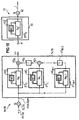
- the announcement system 10 contains in addition to an announcement device 12 and one Speech recognition device 14 as functionally essential Components a detector device 16, a Echo canceller 18 and one Damping device 20.
- the announcement system 10 contains furthermore a multiplier 22, the inputs of which the announcement device 12 and the damping device 20 are connected and its output to the echo canceller 18 and the detector device 16 connected. Furthermore, the exit of the Multiplier 22 on an output 23 of the announcement system 10, via which the announcement is supplied to the user becomes.
- the announcement is based on a digital announcement signal An that in a known manner by means of a D / A converter (not shown) into an analog one and then audible to the user Signal is converted.
- voice input of the user through A-D conversion of one of the voice input corresponding analog signal, a digital voice input signal Sp generated that the announcement system 10 via an input 24 is supplied.
- the announcement signal On and the speech input signal Sp are fed to the detector unit 16, which in to be described, a simultaneous occurrence of Announcement and voice input.
- the detector device 16 inputs announcement and voice input Detector signal Dt with the logic value 1, while for the In the event that announcement and voice input do not coincide superimpose, the detector signal Dt assumes the logic value 0.
- the echo canceller is used via the detector signal Dt 18 and the damping device 20 controlled.
- the volume of the Announcement can be varied. Will be inside the detector device 16 a simultaneous occurrence of voice input and Announcement detected, the damping device 20 with the Logic value 1 of the detector signal Dt driven. In this Fall in the damping device 20 becomes a first damping factor a set a reduction in Volume of the announcement caused by the multiplier 22 is supplied and this from the announcement device 12 originating announcement signal attenuates accordingly. Is still after a predetermined monitoring period a temporal overlay of announcement and voice input before, so the announcement signal is by means of a second Damping factor a damped so much that an announcement pause occurs, as will be explained in more detail later.
- the echo canceller 18 has the task of Exempt voice input from an announcement echo. This will generated in that the announcement about one in Figure 1 with EP designated echo path from the output 23 to the input 24 of the Announcement system 10 is transmitted and there in the to be processed Voice input signal Sp is received. To the announcement echo to remove from the voice input signal Sp, the Transmission properties of the echo path EP, i.e. his Transfer function, from the echo canceller 18 reproduced in a rapidly converging adaptation process.
- the echo canceller 18 is by the Detector signal Dt controlled and generated from the announcement signal To that fed to him by the multiplier 22 is a compensation signal simulated by the announcement echo y on the adder 25 from the speech signal Sp is subtracted.
- the speech recognition device 14 stands such a digital difference signal d from the announcement echo liberated voice input and after another Processing step which will be explained later Useful signal t available.
- the speech recognition facility 14 can be the relevant in a known manner Message content can be obtained from voice input.
- FIG. 2 is a block diagram of the detector device 16 shown.
- the detector device 16 contains in parallel switched an announcement averaging element 26 and an input averaging element 28. These components are with an adder 30 linked, arranged in parallel with a digital Follow pulse filter 32 and a digital basic filter 34.
- the pulse filter 32 and the basic filter 34 are with a Evaluation unit 36 connected.
- the invention is intended to be used in the following with reference to FIGS. 2 to 12 will be explained using an example in which the announcement signal An and the speech input signal Sp each a sequence of Samples are taken by sampling the corresponding ones analog signals are generated with a sampling rate of 8 kHz.
- the announcement averaging element 26 determines from the announcement signal To an average energy content ⁇ An ⁇ , for a suitable one Number of samples of the announcement signal to one Absolute value formation, logarithmization and averaging is carried out. The number of samples is for this Example set at 80, so that the announcement signal An over an averaging period of 10 ms is averaged.
- the Averaging can e.g. in a known manner Low pass filtering is done.
- a middle so captured Energy content ⁇ An ⁇ of the announcement signal An becomes the Adder 30 supplied.
- the pulse filter 32 and the basic filter 34 still produce in a pulse measure P from the difference Elog or a basic dimension G, which is fed to the evaluation unit 36 become.
- the pulse measure P with the Basic dimension G plus a predetermined threshold OF compared. If the pulse measure P is larger than that around Threshold value OF increased basic dimension G, so the evaluation unit 36 the evaluation signal Dt with the logic value 1, that the simultaneous appearance of announcement and voice input displays.
- the digital pulse filter 32 is shown, the the pulse measure from the difference Elog of the current time window P generated.
- the pulse filter 32 contains two processing branches. In the first processing branch are connected in series first adder 38, a multiplier 40 and a second adder 42 included. The second adder 42 is followed by a delay element 44, the Output connected to the input of the first adder 38 is.
- the delay element 44 generates a signal delay Ts, which corresponds to the length of a time window.
- the digital filters work a clock frequency of 8 kHz, so that the signal delay Ts and thus the length of a time window is set at 125 ns is.
- the second processing branch there is an adder 46 and an adapter 48 connected in series. Of the Input of adder 46 is also connected to the output of Delay element 44 connected.
- FIG. 4 is to be used, in which a trough-shaped characteristic curve 50 (solid line) which is symmetrical to the zero axis and which characterizes a first adaptation function is shown.
- the adaptation function according to FIG. 4 indicates the relationship between a first auxiliary variable D1 and a first adaptation variable M1, which is used in the first processing branch of the pulse filter 32 to determine the pulse measure P.
- the auxiliary variable D1 gives a measure of the change in the pulse measures P of two successive time windows.
- the adaptation element 48 From the auxiliary variable D1 according to the relationship (1), the adaptation element 48 generates the adaptation variable M1 according to the characteristic curve 50 according to FIG. 4, which is fed to the multiplication element 40.
- the pulse measure P (n-1) of the last processed time window n-1 is subtracted from the difference Elog (n) of the current time window n at the adder 38. The result of this subtraction is multiplied by the adaptation variable M1 at the multiplication element 40.
- the pulse measure P (n) of the time window n currently to be processed is the sum of two complementary weights Shares.
- the weighting of the two shares is done via the Adaptation size M1, which generally has values between 0 and 1 can accept.
- the second share dominates for large values of M1 M1 ⁇ Elog (n), so that the pulse measure P (n) of the current time window n essentially by the difference Elog (n) des current time window n is given.
- the adaptation size M1 thus regulates the weighting with which the pulse measure P (n) of the current time window n from the previous pulse measure P (n-1) and the current difference Elog (n).
- the pulse measure P (n) remains for small amounts of D1 of the current time window n compared to the pulse measure P (n-1) of the previous frame n-1 almost unchanged since the first Adaptation function in this value range from D1 small values assumes close to 0.
- D1 For large values of D1 increase the value of the adaptation size M1 too, so that the contribution of the difference Elog (n) of the current time window n becomes larger and the pulse measure P (n) of the current time window n follows the difference Elog.
- the effect of the digital pulse filter 32 according to FIG. 3 is accordingly in that strong pulses over time the difference Elog can be detected while slight fluctuations in Elog to be smoothed.
- the first adaptation function with the characteristic curve 50 according to FIG. 4 can be approximated by a rectangular function which assumes a minimum value M1 min for amount values of D1 smaller than a predetermined amplitude value s and a maximum value M1 max for amount values of D1 greater than the predetermined amplitude value s.
- the predetermined amplitude value s is 10
- the minimum value M1 min is 1/32
- the maximum value M1 max is 1/2.
- the rectangular function is represented in FIG. 4 by a rectangular characteristic curve 52 (dashed line).
- the minimum value M1 min is shown exaggeratedly large in FIG.
- the amplitude value s is set in such a way that the pulse measure P remains essentially unaffected by slight fluctuations in the difference Elog, but strong pulses of Elog are reflected in the time course of P, which is illustrated later with reference to FIGS. 10 and 11.
- FIG. 5 shows the digital basic filter 34 which from the difference Elog (n) of the current time window n das Basic dimension G is generated.
- the basic filter 34 is essentially constructed in the same way as the pulse filter 14, so that on a detailed description of its structure at this point can be dispensed with.
- the components of the basic filter 34 which correspond to the components of the pulse filter 32 according to FIG. 2, are in Figure 5 with the reference numerals of the components the pulse filter 32 provided.
- the digital basic filter 34 additionally contains a further adder 54, which on Output of the first processing branch is arranged. On the adder 54 becomes that of the adder 42 output basic dimension G and the predetermined threshold OF added and the result of this addition is output.
- the Adding the OF threshold ensures a safety margin of the basic measure G compared to the pulse measure P.
- the Threshold value OF is set so that the safety distance is about 6 dB to 10 dB.
- the basic filter 34 also differs from the pulse filter 32 in that a second adaptation variable M2, which is different from the first adaptation variable M1 and is fed to the multiplication element 40, is determined in the adaptation element 48.
- the determination of the second adaptation variable M2 is based on a second adaptation function, the characteristic curve 56 of which is shown as a solid line in FIG. 6.
- the second adaptation variable M2 is determined as a function of a second auxiliary variable D2, which is generated by subtracting the basic dimension G (n-1) delayed by Ts from the difference Elog (n) of the current time window n on the adder 46 of the basic filter 34 .
- the characteristic curve 56 falls from a higher level to a lower level near 0 within a transition region II, which predominantly contains negative values of D2.
- the second adaptation variable M2 determined according to the characteristic curve 56 becomes in the first processing branch used to calculate the basic dimension G (n) of the current time window n.
- the basic dimension G (n-1) of the last processed time window n-1 is subtracted from the difference Elog (n) of the current time window n and the result of this subtraction is multiplied at the multiplication element 40 by the second adaptation variable M2.
- the result of this multiplication and the basic dimension G (n-1) of the last processed time window n-1 are added to the adder 42.
- Adaptation size M2 are weighted complementarily to each other.
- M2 can generally take values between 0 and 1.
- M2 decreases, the contribution M2 ⁇ Elog (n) decreased.
- the basic dimension G therefore remains at one sudden increase in difference Elog, i.e. on insertion the speech input during the announcement, essentially unchanged.
- D2 i.e. for bigger ones Values of M2
- Elog (n) carries the difference Elog (n) of the current Time window n for the pulse measure G (n).
- I denotes according to the equation (3) an area where the difference elog (n) versus the basic dimension G (n-1) drops significantly. This is the case as soon as the voice input is ended during the announcement.
- the second adaptation function can be approximated by a step function.
- a step-shaped characteristic curve 58 is shown in dashed lines in FIG. 6 as an approximation to the second adaptation function characterized by the characteristic curve 56.
- the adaptation variable M2 takes a maximum value M2 max in region I, which is given by values of D2 smaller than a predetermined negative value S1, in region II, which by values of D2 greater than or equal to the predetermined negative value S1 and less than or equal to a predetermined positive value S2, an intermediate value M2 zw and in the region III, which is given by values of D2 greater than the predetermined positive value S2, a minimum value M2 min .
- the second adaptation variable M2 is determined in accordance with the characteristic curve 58.
- the characteristic curve 58 is equal to -20 by S1, S2 equal to 10, M2 max is equal to 1/16, M2 zw equal to 1/128 and M2 characterized min is equal to 1/32768.
- the method of operation of the detector device 16 just explained is in the following with reference to Figures 7 to 12 using the example a concrete announcement and a concrete speech input illustrated.
- the voice input is the time of the announcement partially overlaid.
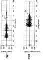
- Figure 7 is the time course the announcement signal An, which corresponds to an announcement "Siemens", displayed in a time range from 0 to 1.8 seconds.
- the speech signal Sp shown that the A-D conversion of a voice input "Mueller" won.
- FIGS. 7 and 8 there is a partial temporal overlay of the announcement signal On and the voice input signal Sp before.
- the echo path EP after Figure 1 is in this example by one over the entire Frequency range largely constant attenuation of approx.
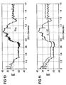
- the announcement signal On and the speech input signal Sp become after absolute value formation, logarithmization and averaging the signal difference Elog formed, the temporal Course is shown in Figure 10.
- the announcement signal An occurs on its own, it is temporal course of the signal difference Elog largely constant.
- the digital filters 32 and 34 generate from the signal difference Elog the pulse measure P in the manner described above and the basic dimension G plus the predetermined threshold OF, whose time course is shown in Figure 11. To the Times when the announcement occurs alone is around Threshold value OF increased basic dimension, i.e.
- the threshold value OF is set to approximately 10 dB.
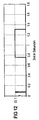
- the detector signal Dt with the logic value 0 as shown in FIG is.
- the pulse measure P exceeds the sum Basic dimension G and threshold value OF, and the detector device 16 outputs the detector signal Dt with the logic value 1, as is also shown in Figure 12.
- a comparison of Figure 7, 8 and 12 shows that the detector device 16 is a simultaneous Reliable occurrence of announcement and voice input and detected with negligible delay.
- the damping device 20 is in the embodiment according to Figure 1 provided to vary the announcement volume.
- the announcement signal at the beginning of a time Superimposition with the first damping factor a subdued.
- the first damping factor a can, for example cause an attenuation of 12 dB.
- the second damping factor a is set, which can be chosen so large, for example, that it an almost infinitely large attenuation of the announcement and such Announcement pause.
- FIG. 14 explains how the Announcement in the announcement system 10 is controlled.
- the procedural step 100 is by means of a voice input from the user an announcement selected from the announcement menu.
- the announcement will released in step 102 and the corresponding announcement signal At undamped to the output 23 of the announcement system 10 after Figure 13 transferred.
- the detector device 16 continuously checked whether the user of the announcement system 10 a voice input according to FIG. 13 via input 24 feeds, i.e. whether announcement and voice input at the same time respectively. As long as this is not the case, the detector signal Dt the logical value 0, and the announcement signal An remains undamped. This is normal operation in step 102 designated.
- Step 104 becomes the simultaneous appearance of announcement and Voice input monitored.
- the switchable Damping device 20 the first damping factor a of e.g. 12 dB on.
- a first time circuit not shown in the figures activated, which is set to the specified monitoring duration is. If the voice input is within the monitoring period ends, the detector signal Dt goes from 1 to 0 over, and the damping device 20 is caused to Cancellation of damping. In Figure 14, this corresponds to the return from step 104 to step 102.
- the damping factor becomes after the monitoring period has expired a in step 106 approximately to infinity switched, which creates a pause in the announcement.
- the damping factor becomes after the monitoring period has expired a in step 106 approximately to infinity switched, which creates a pause in the announcement.
- the detection signal It becomes the announcement system 10 according to FIG 13 returned to a defined initial state, in which the user receives a next announcement from the announcement menu can choose. In Figure 14, this corresponds to the return after step 100.
- the control unit 60 holds the announcement device 12 after the end of the pause in step 108. Furthermore, the announcement device 12 caused by the control unit 60, an announcement segment, i.e. the word or phrase to be set before the voice input, i.e. before the temporal overlay of announcement and voice input, has been announced.
- the announcement segment is described in the Embodiment the word that last before the Monitoring, i.e. before switching the attenuation from 0 dB to 12 dB, has been announced by the announcement device 12. It then continues to step 102 where the damping is canceled and the announcement is released.
- Speech recognition device 14 outputs an error signal, if she did not recognize the voice input.
- the error signal the detector device 20 and the control unit 60, which the announcement device 12 in step 108 stops and the announcement segment as described above that was announced before the monitoring.
- the mode of operation is described below with reference to FIGS. 15 to 23 of the echo canceller 18 explains the is shown in Figures 1 and 13.
- the echo canceller 18 forms by increasing the sampling rate and decorrelation of the announcement signal An and the speech input signal Sp the announcement echo in an adaptive process and removed this from the speech input signal Sp.
- this is Announcement system 10 shown in an embodiment in which the damping device 20, the multiplier 22 and the control unit 60 are not provided.
- the components 20, 22 and 60 are for the functioning of the echo canceller 18 not essential. The following However, what has been explained applies equally to the embodiments according to FIG. 1 and FIG. 13.
- FIG. 1 is the echo canceller 18 for the sake of clarity in the reference number 18 designated symbol summarized without the arrangement of their To express components in the announcement system 10.
- Their components are now shown in detail in FIG shown.
- the first interpolation device 64 contains a first in series Sampling rate enhancer 72 and a first digital decorrelation filter 74.
- the second interpolation device 66 is constructed in the same way as the first interpolation device 64 and thus contains a second sampling rate enhancer connected in series 76 and a second decorrelation filter 78.
- the first and second sample rate enhancers 72, 76 and the first and the second decorrelation filter 74, 78 can each be identical components.
- the decimator 70 consists of a digital equalization filter 80 and a subsequent sample rate lower 82.
- the announcement signal On and the speech input signal Sp are a sequence of samples, the time interval between them is determined by a predetermined first sampling period.
- the first predetermined sampling period in the following as long Sampling period and accordingly the sampling rate of the announcement signal On and the voice input signal Sp as a low sampling rate designated. Samples whose sampling times by the low sampling rate are given below called "regular".
- the announcement signal On and the speech input signal Sp become the Detector unit 16 fed, which occurs simultaneously of announcement and voice input.
- the detector device 16 drives the echo cancellation filter 68 and deactivates the coefficient adaptation explained later if Announcement and voice input occur simultaneously. To this This ensures that the adaptation of the echo cancellation filter 68 only occurs when the announcement is alone occurs.
- the announcement signal is On and Speech input signal Sp with the predetermined low sampling rate scanned.
- the first interpolation device 64 and the second interpolation device 66 have the function from the announcement signal On or the speech input signal Sp generate a signal whose sampling rate is increased and its samples also at least up to a certain point Degrees are decorrelated.
- the announcement signal On which by the first interpolation device 64 in its sampling rate is increased and also decorrelated, is referred to below as interpolated announcement signal x, its sampling rate as high Designated sampling rate.
- the voice input signal is correspondingly Sp that pass through the second interpolation sub-filter 66 has referred to as an interpolated speech input signal v.
- the first sampling rate increase 72 increases the sampling rate or decreases the sampling period of the announcement signal An by one predetermined factor M by switching between successive regular samples of the announcement signal to M-1 zero values inserts. Is the high sampling rate with F and therefore the short one If the sampling period is set to T, this is the low sampling rate by the value of the quotient of F and M and the long Sampling period by the value of the product of M and T given.
- modified announcement signal in the following note is processed in the first decorrelation filter 74.
- the transfer function H 'of the first decorrelation filter 74 is set depending on the announcement that the samples of the interpolated announcement signal x are at least partially decorrelated.
- the second interpolation device 66 In the same way generates the second interpolation device 66 from the Speech input signal Sp is initially a modified one Voice input signal, hereinafter called Spm, in which between successive, regular samples M-1 zero values are inserted, and from this the interpolated Speech input signal v, the sampling rate by the factor M is increased and its samples are also decorrelated, like the samples of the interpolated announcement signal x.
- Spm modified one Voice input signal
- the echo cancellation filter 68 has the task of voice input to get rid of the announcement echo that comes through the echo path Transfer EP from output 23 to input 24 of announcement system 10 and there in the speech input signal to be processed Sp comes in, as shown in Figure 15. To do that Remove announcement echo from the voice input signal Sp, the transmission properties of the echo path EP, i.e. its transfer function, from the echo cancellation filter 68 in a rapidly converging adaptation process replicated. The echo cancellation filter 68 will interpolated announcement signal x supplied. The echo cancellation filter 68 generated in a manner to be described the compensation signal y with the predetermined high sampling rate. At the adder 25, the compensation signal y subtracted from the interpolated speech input signal v and the difference signal d is forwarded to the decimator device 70.
- the sample rate low 82 finally conducts the useful signal t determined in this way to the speech recognition device 14 further.
- the useful signal t is like that Announcement signal on and the speech input signal Sp with the predetermined low sampling rate, i.e. of the time interval between two successive samples is equal to the specified long sampling period.
- the speech recognition facility 14 can be the relevant in a known manner Message content can be obtained from voice input.
- the first interpolation device 64 and the second interpolation device 66 can be used in the Announcement system 10 according to FIG. 15 can be constructed identically. Out for this reason, in the following with reference to FIGS. 16, 17 and 19 the structure and mode of operation of the first interpolation device 64 explained without again on the second Interpolation device 66 to enter. For the second Interpolation device 66 applies to the first interpolation device 64 Explained accordingly. In the figure 16, 17 and 19 are also the reference numerals of the second Interpolation device 64 entered.
- the first interpolation device 64 and the decimator device 70 are shown in FIG. As mentioned at the beginning, the first interpolation device 64 is given by the first decorrelation filter 74 and the upstream sampling rate enhancer 72.
- the sampling rate enhancer 72 increases the sampling rate of the announcement signal An by the predetermined factor M by inserting M-1 zero values between two successive regular sampling values, and thus generates the modified announcement signal Anm.
- the first decorrelation filter 74 contains M parallel decorrelation sub-filters IFT 0 to IFT M-1 , to which the modified announcement signal Anm is supplied.
- Each of the decorrelation sub-filters IFT 0 to IFT M-1 can be divided into "memoryless" networks N 0 'to N' M-1 and delay units VE ' 0 to VE' M-1 .
- memoryless networks are to be understood as networks which can contain addition elements and multiplication elements, but no delay elements.
- the delay units VE ' 0 to VE' M-1 delay the modified announcement signal Anm by the long sampling period or a multiple of the long sampling period.
- the long sampling period is M times the short sampling period T.
- the outputs of the interpolation sub-filters IFT 0 to IFT M-1 are connected to one another via a series arrangement in which M-1 delay elements VG 0 to VG M-2 and M addition elements AD 0 to AD M-1 are arranged in an alternating sequence.
- the outputs of the first M-2 decorrelation sub-filters IFT 0 to IFT M-2 are each connected to the corresponding adder AD 0 to AD M-2 , while the output of the last decorrelation sub - filter IFT M-1 is connected to the delay element VG M-2 .
- the delay elements VG 0 to VG M-2 each provide a signal delay corresponding to the short sampling period T.
- the first decorrelation filter 74 outputs the interpolated, ie the announcement signal x increased and at least partially decorrelated in the sampling rate.
- the modified announcement signal Anm sampled at the high sampling rate can accordingly be processed in the first decorrelation filter 74 essentially at the low sampling rate, since the decorrelation sub-filters IFT 0 to IFT M-1 are operated at the low sampling rate.
- Each of the M-1 zero values inserted between two regular sample values is converted into an intermediate value by one of the decorrelation sub-filters IFT 1 to IFT M-1 in accordance with the associated transfer function H ' i , so that the announcement signal modified by the insertion of the zero values Note that the interpolated announcement signal x is generated.
- the degree of the desired decorrelation can be set as a function of the known announcement signal An via the transfer functions H ' i of the decorrelation sub-filters IFT 0 to IFT M-1 .
- FIG. 16 shows the decimator device 70, which consists of the equalization filter 80 and the subsequent sampling rate reducer 82.
- the equalization filter 80 contains only a single equalization sub-filter DFT 0 , which, like the decorrelation sub-filters IFT 0 to IFT M-1 of the decorrelation filters 74 and 78, can be subdivided into a memory-free network N 0 ′′ and a delay unit VE 0 ′′.
- the signal delays caused by the delay unit VE 0 ′′ correspond to the long sampling period, that is to say M times the short sampling period T, or a multiple thereof.
- the compensation filter IFT 0 is therefore also operated at the low sampling rate.
- the signal changes which have been caused by the transmission of the first decorrelation sub-filter IFT 0 of the decorrelation filters 74, 78 are compensated.
- the M-1 intermediate values of the difference signal d that occur between two successive regular sampling values are masked out by the sampling rate lower 82, so that the useful signal t sampled with the low sampling rate is available at the output of the decimator device 70.
- the decimator device 70 accordingly ensures that the sampling values of the useful signal t are not falsified by the measures for increasing the sampling rate and decorrelation, that is to say that the speech input signal, aside from the desired echo suppression after interpolation and subsequent sampling rate reduction, appears as before.
- FIG. 17 shows the first and second interpolation devices 64 and 68 and the corresponding decimator device 70 for an exemplary embodiment in which the first decorrelation partial filter IFT 0 is a simple pass-through filter which does not include the modified announcement signal or speech input signal Spm to the adder AD 0 Changes.
- the equalizing filter DFT 0 is also a simple pass filter.
- the echo suppression filter 68 generates the compensation signal y from the interpolated announcement signal x, which is fed to it by the first interpolation device 64.
- the compensation signal y is based on N filter coefficients c 0 to c N-1 , which an adaptation unit 84 of the echo suppression filter 68 supplies.
- the adaptation unit 84 determines the N filter coefficients c 0 to c N-1 according to the LMS algorithm as a function of the difference signal d, which is formed in the adder 25 from the compensation signal y and the interpolated speech input signal v.
- the echo cancellation filter 68 contains a delay chain with N-1 delay elements 86, which delay the interpolated announcement signal x by the long sampling period, ie by M times the short sampling period T. Branching off from the delay chain, N multiplication elements 88 are arranged in parallel, each of which is controlled by the adaptation unit 84 with one of the N filter coefficients c 0 to c N-1 . The outputs of the multiplication elements 88 are linked to one another via a series arrangement of N-1 addition elements 90. The last addition element of the series arrangement, which is connected to the multiplication element controlled by the filter coefficient c N-1 , supplies the compensation signal y to the addition element 25.
- the filter coefficients c 0 to c N-1 are determined in the adaptation unit 84 according to the LMS algorithm. For this purpose, in the time in which the announcement occurs alone, ie in which there are no "double talking" conditions, essentially the square of the magnitude of the difference signal d, which indicates the deviation of the compensation signal y from the interpolated speech input signal v, by adapting the filter coefficients c 0 to c N-1 minimized. Since the delay elements 86 of the delay chain each cause a signal delay corresponding to the long sampling period, only those samples of the interpolated input signal x weighted with the filter coefficients c 0 to c N-1 are included in a single sample of the compensation signal y, the time interval of which is due to the long sampling period given is.
- the echo canceller 18 turns on Hand explained concrete embodiments.
- Figure 19 are the first Interpolation device 64 and decimator device 70 shown for an example in which a sample rate increase is made by a factor of two.
- the second Interpolation device 66 constructed in the same way as the first Interpolation device 64, so that in the following with regard to the announcement signal to the voice input signal Sp applies.
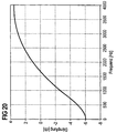
- the interpolation device 64 has the task of the announcement signal On between successive regular samples such to interpolate that the coloring shown in Figure 20 the announcement is largely compensated for.
- the frequency response of the damping is plotted as it is typically for human language and thus for the Announcement and voice input.
- the one in Figure 20 shown course shows the properties of a so-called Low pass coloring.
- the decorrelation filter 74, 78 contains the two decorrelation sub-filters IFT 0 and IFT 1 .
- the first decorrelation sub-filter IFT 0 is designed as a simple pass filter, the transfer function H ' 0 of which is given by relation (7).
- the equalizing filter 80 contains only one equalizing sub-filter DFT 0 , which is also designed as a pass filter in accordance with the relationship (7).
- the first decorrelation sub-filter IFT 1 contains a delay element 92, which causes a k-fold signal delay of twice the short sampling period T. k is an integer, non-negative number.
- Delay element 92 is followed by a delay element 94, which generates a signal delay of twice the short sampling period, and a multiplication element 96, the output of which leads to the input of an adder 98.
- a multiplication element 100 is provided branching between the delay elements 52 and 54, the output of which is also routed to the addition element 98.
- the multiplication factor of the multiplication element 96 is set at 1 and the multiplication factor of the multiplication element 100 at -1/2.
- the transfer function H ' 1 of the decorrelation sub-filter shown in FIG. 19 is suitable for largely eliminating the coloring of the announcement or the voice input shown in FIG. The efficiency with which this is possible depends on the constant k, as shown below.
- the multiplication elements 96, 100 are designated in FIGS. 16 and 17 as a memoryless network N 1 ', while the delay elements 92, 94 in these figures correspond to the delay unit VE 1 '.
- the announcement signal An or the speech input signal Sp is first fed to the sampling rate enhancer 72 or 76, which generates the modified announcement signal Anm or speech input signal Spm which is increased in the sampling rate.
- the announcement signal An and the speech input signal Sp can be sampled with a sampling frequency corresponding to the low sampling rate, for example 8 kHz.
- the sampling rate enhancer 72 or 76 thus increases the sampling frequency to 16 kHz.
- the modified announcement signal or speech input signal Spm are now processed in a first processing branch by the first decorrelation sub-filter IFT 0 and in a second processing branch by the second decorrelation filter IFT 1 .
- the two output signals of the first decorrelation sub-filter IFT 0 and the second decorrelation sub-filter IFT 1 which are delayed by a short sampling period by the delay element VG 0 , are added and output as an interpolated announcement signal x or as an interpolated speech input signal.
- the differential signal d is unchanged by the compensation filter 80 forwarded to the sample rate low 82. This leads the necessary in this embodiment Halving the sampling frequency from 16 kHz to 8 kHz by by taking every second sample of the difference signal d fades out.
- the useful signal t generated in this way like the announcement signal On and the speech input signal Sp with the sampling frequency of 8 kHz is sampled, the speech recognition unit 14 fed.
- the number N of filter coefficients c 0 to c N-1 is set at 64 both for the two exemplary embodiments of the invention and for the known echo suppression filter.
- N the convergence of the coefficient adaptation
- two variables are used in the following, namely the average attenuation ERLE, "Error Return Loss Enhancement", of the echo path EP and the deviation of a coefficient vector summarizing the current filter coefficients from an optimal coefficient vector Copt, by which the optimal filter coefficients are given.
- Figure 21 illustrates the convergence behavior of a conventional one Echo suppression filter based on the LMS algorithm is working.
- conventional echo cancellation no increase in sampling rate and decorrelation of the announcement signal and the voice input signal.
- 22 shows the convergence behavior of the digital filter device shown in Figure 19, in which the constant k of Delay element 92 for this exemplary embodiment with 0 is scheduled.
- the time course of the average damping Alder of the echo path EP and the deviation from the optimal one Coefficient coefficient Copt reflect the significantly improved Convergence behavior of the digital filter device according to the invention again. If the constant k is increased, e.g. so, that they are greater than or equal to half the number of filter coefficients is, the convergence behavior of the digital filter device be significantly improved again.
- Figure 23 is the convergence behavior of an embodiment the digital filter device according to FIG. 19 shown in which the constant k is set to 32. This measure makes the correlation between successive Samples of the interpolated input signal x and between successive samples of the interpolated Speech input signals v further reduced so that the Adaptation of the filter coefficients as part of the LMS algorithm can be carried out much faster.
Landscapes
- Engineering & Computer Science (AREA)
- Computational Linguistics (AREA)
- Health & Medical Sciences (AREA)
- Audiology, Speech & Language Pathology (AREA)
- Human Computer Interaction (AREA)
- Physics & Mathematics (AREA)
- Acoustics & Sound (AREA)
- Multimedia (AREA)
- Cable Transmission Systems, Equalization Of Radio And Reduction Of Echo (AREA)
Abstract
Description
- Figur 1
- ein Blockdiagramm eines sprachgesteuerten Ansagesystems,
- Figur 2
- ein Blockdiagramm einer Detektoreinrichtung zum Erkennen gleichzeitig auftretender Ansage und Spracheingabe,
- Figur 3
- eine Schaltungsanordnung eines digitalen Pulsfilters der Detektoreinrichtung nach Figur 2,
- Figur 4
- eine erste Adaptionsfunktion, die in dem Pulsfilter nach Figur 3 berücksichtigt wird,
- Figur 5
- eine Schaltungsanordnung eines digitalen Grundfilters der Detektoreinrichtung nach Figur 2,
- Figur 6
- eine zweite Adaptionsfunktion, die in dem Grundfilter nach Figur 5 berücksichtigt wird,
- Figur 7
- den zeitlichen Verlauf eines Ansagesignals,
- Figur 8
- den zeitlichen Verlauf eines Spracheingabesignals,
- Figur 9
- eine Impulsantwort eines Echopfades für das Beispiel nach Figur 7 und 8,
- Figur 10
- den zeitlichen Verlauf der Signaldifferenz von mittlerem Ansageenergiegehalt und mittlerem Spracheingabeenergiegehalt für das Beispiel nach Figur 7 und 8,
- Figur 11
- den zeitlichen Verlauf von Pulsmaß und Grundmaß für das Beispiel nach Figur 7 und 8,
- Figur 12
- den zeitlichen Verlauf eines Detektorsignals für das Beispiel nach Figur 7 und 8,
- Figur 13
- ein Blockdiagramm einer alternativen Ausführungsform des Ansagesystems,
- Figur 14
- ein Ablaufdiagramm zum Steuern des Ansagesystems nach Figur 13,
- Figur 15
- ein Blockdiagramm des sprachgesteuerten Ansagesystems mit einer Echounterdrückungseinrichtung in einer weiteren Ausführungsform,
- Figur 16
- ein Blockdiagramm einer Interpolationseinrichtung und einer Dezimatoreinrichtung der Echounterdrückungseinrichtung,
- Figur 17
- ein Blockdiagramm der Interpolationseinrichtung und der Dezimatoreinrichtung in einer speziellen Ausführungsform,
- Figur 18
- ein Blockdiagramm eines Echounterdrückungsfilters der Echounterdrückungseinrichtung,
- Figur 19
- eine Schaltungsanordnung der Interpolationseinrichtung und der Dezimatoreinrichtung der Echounterdrückungseinrichtung in einem Ausführungsbeispiel,
- Figur 20
- den Frequenzverlauf der Dämpfung eines mit der Echounterdrückungseinrichtung nach Figur 19 verarbeiteten Ansagesignals,
- Figur 21
- den zeitlichen Verlauf der mittleren Dämpfung des Echopfades und der Abweichung eines aktuellen Satzes von Filterkoeffizienten von einem optimalen Satz für eine bekannte Echounterdrückungseinrichtung,
- Figur 22
- den zeitlichen Verlauf der mittleren Dämpfung des Echopfades und der Abweichung des aktuellen Satzes von Filterkoeffizienten von dem optimalen Satz für ein Ausführungsbeispiel der Echounterdrückungseinrichtung nach Figur 19 und
- Figur 23
- den zeitlichen Verlauf der mittleren Dämpfung des Echopfades und der Abweichung des aktuellen Satzes von Filterkoeffizienten von dem optimalen Satz für ein weiteres Ausführungsbeispiel der Echounterdrückungseinrichtung nach Figur 19.
Claims (13)
- Verfahren zum Steuern eines Ansagesystems (10),bei dem durch eine Ansageeinrichtung (12) eine Ansage in Form eines digitalen Ansagesignals (An) erzeugt wird,eine zeitliche Überlagerung der Ansage und einer Spracheingabe erfaßt wird,ein Kompensationssignal (y), durch das ein in einem digitalen Spracheingabesignal (Sp) enthaltenes Ansageecho nachgebildet wird, in einem adaptiven, digitalen Echounterdrückungsfilter (68) ermittelt wird, dessen Filterkoeffizienten (c0 bis cN-1) in einem Zeitintervall adaptiert werden, in dem die Ansage im wesentlichen allein auftritt,und bei dem im wesentlichen ein Differenzsignal (d, t) aus Spracheingabesignal (Sp, v) und Kompensationssignal (y) von einer Spracherkennungseinrichtung (14) verarbeitet wird.
- Verfahren nach Anspruch 1, dadurch gekennzeichnet, daß die Adaption der Filterkoeffizienten beendet wird, wenn eine zeitliche Überlagerung von Ansage und Spracheingabe erfaßt wird.
- Verfahren nach Anspruch 1 oder 2, dadurch gekennzeichnet, daß die Adaption der Filterkoeffizienten nach einem Verfahren zur Minimierung der mittleren Fehlerquadrate durchgeführt wird.
- Verfahren nach einem der vorhergehenden Ansprüche, dadurch gekennzeichnet, daß die zeitliche Überlagerung von Ansage und Spracheingabe durch eine Detektoreinrichtung (16) erfaßt wird, der das Ansagesignal (An) und das Spracheingabesignal (Sp) zugeführt werden und die ein Detektorsignal (Dt) erzeugt.
- Verfahren nach Anspruch 4, dadurch gekennzeichnet, daß das Echounterdrückungsfilter (68) durch das Detektorsignal (Dt) angesteuert wird und das Kompensationssignal (y) und das Spracheingabesignal (Sp, v) einem Additionsglied (25) zugeführt werden, welches das Differenzsignal (d) ermittelt und dieses an die Spracherkennungseinrichtung (14) und an das Echounterdrückungsfilter (68) abgibt.
- Verfahren nach einem der vorhergehenden Ansprüche, dadurch gekennzeichnet, daß das Ansagesignal (An) gedämpft wird, wenn eine zeitliche Überlagerung von Ansage und Spracheingabe festgestellt wird.
- Verfahren nach Anspruch 6, dadurch gekennzeichnet, daß das Ansagesignal (An) stufenweise gedämpft wird.
- Verfahren nach Anspruch 6 oder 7, dadurch gekennzeichnet, daß eine Dämpfungsvorrichtung (20) durch das Detektorsignal (Dt) angesteuert wird und einem Multiplikationsglied (22) mindestens einen Dämpfungsfaktor (a) zuführt, mit dem das Ansagesignal (An) multipliziert wird.
- Ansagesystem zum Durchführen des Verfahrens nach einem der Ansprüche 1 bis 8, mit einer Ansageeinrichtung (12) zum Erzeugen einer Ansage in Form eines digitalen Ansagesignals (An),einer Detektoreinrichtung (16) zum Erfassen einer zeitlichen Überlagerung der Ansage und einer Spracheingabe,einem adaptiven, digitalen Echounterdrückungsfilter (68), das ein Kompensationssignal (y) ermittelt, durch das ein in einem digitalen Spracheingabesignal (Sp) enthaltenes Ansageecho nachgebildet wird, und dessen Filterkoeffizienten (c0 bis cN-1) in einem Zeitintervall adaptiert werden, in dem die Ansage im wesentlichen allein auftritt,und mit einer Spracherkennungseinrichtung (14) zum Verarbeiten eines Differenzsignals (d) aus Spracheingabesignal (Sp) und Kompensationssignal (y).
- Ansagesystem nach Anspruch 9, dadurch gekennzeichnet, daß das Echounterdrückungsfilter (68) ein nach einem Verfahren zur Minimierung der mittleren Fehlerquadrate arbeitendes, adaptives Digitalfilter ist.
- Ansagesysem nach Anspruch 9 oder 10, dadurch gekennzeichnet, daß der Detektoreinrichtung (16) das Ansagesignal (An) und das Spracheingabesignal (Sp) zugeführt werden und sie ein Detektorsignal (Dt) erzeugt.
- Ansagesystem nach Anspruch 11, dadurch gekennzeichnet, daß die Detektoreinrichtung (16) mit dem Echounterdrückungsfilter (68) verbunden ist und dieses durch das Detektorsignal (Dt) ansteuert und daß das Echounterdrückungsfilter (68) mit einem der Spracherkennungseinrichtung (14) vorgeschalteten Additionsglied (25) verbunden ist, dem das Kompensationssignal (y) und das Spracheingabesignal (Sp) zugeführt werden und welches das Differenzsignal (d) ermittelt und dieses an die Spracherkennungseinrichtung (14) und das Echounterdrückungsfilter (68) ausgibt.
- Ansagesystem nach Anspruch 11 oder 12, gekennzeichnet durch eine mit der Detektoreinrichtung (16) verbundene Dämpfungsvorrichtung (20), die durch das Detektorsignal (Dt) angesteuert wird und bei einer zeitlichen Überlagerung von Ansage und Spracheingabe einem mit ihr verbundenen Multiplikationsglied (22) mindestens einen Dämpfungsfaktor (a) zuführt, mit dem das Ansagesignal (An) multipliziert wird.
Applications Claiming Priority (2)
| Application Number | Priority Date | Filing Date | Title |
|---|---|---|---|
| DE19740217 | 1997-09-12 | ||
| DE19740217 | 1997-09-12 |
Publications (3)
| Publication Number | Publication Date |
|---|---|
| EP0902414A2 true EP0902414A2 (de) | 1999-03-17 |
| EP0902414A3 EP0902414A3 (de) | 1999-11-03 |
| EP0902414B1 EP0902414B1 (de) | 2003-10-22 |
Family
ID=7842201
Family Applications (1)
| Application Number | Title | Priority Date | Filing Date |
|---|---|---|---|
| EP98115183A Expired - Lifetime EP0902414B1 (de) | 1997-09-12 | 1998-08-12 | Ansagesystem und Verfahren zum Steuern desselben |
Country Status (2)
| Country | Link |
|---|---|
| EP (1) | EP0902414B1 (de) |
| DE (1) | DE59809955D1 (de) |
Family Cites Families (5)
| Publication number | Priority date | Publication date | Assignee | Title |
|---|---|---|---|---|
| US4914692A (en) * | 1987-12-29 | 1990-04-03 | At&T Bell Laboratories | Automatic speech recognition using echo cancellation |
| US5125024A (en) * | 1990-03-28 | 1992-06-23 | At&T Bell Laboratories | Voice response unit |
| US5155760A (en) * | 1991-06-26 | 1992-10-13 | At&T Bell Laboratories | Voice messaging system with voice activated prompt interrupt |
| US5548681A (en) * | 1991-08-13 | 1996-08-20 | Kabushiki Kaisha Toshiba | Speech dialogue system for realizing improved communication between user and system |
| US5708704A (en) * | 1995-04-07 | 1998-01-13 | Texas Instruments Incorporated | Speech recognition method and system with improved voice-activated prompt interrupt capability |
-
1998
- 1998-08-12 DE DE59809955T patent/DE59809955D1/de not_active Expired - Fee Related
- 1998-08-12 EP EP98115183A patent/EP0902414B1/de not_active Expired - Lifetime
Also Published As
| Publication number | Publication date |
|---|---|
| EP0902414A3 (de) | 1999-11-03 |
| DE59809955D1 (de) | 2003-11-27 |
| EP0902414B1 (de) | 2003-10-22 |
Similar Documents
| Publication | Publication Date | Title |
|---|---|---|
| DE2207141C3 (de) | Schaltungsanordnung zur Unterdrückung unerwünschter Sprachsignale mittels eines vorhersagenden Filters | |
| EP0371567B1 (de) | Echokompensator | |
| DE60004539T2 (de) | Teilband-unterdrückung einer akustischen rückkopplung in hörgeräten | |
| DE69024877T2 (de) | Anordnung zur Echoverarbeitung, insbesondere akustisch, für Fernsprechleitung | |
| DE69331223T2 (de) | Netzwerkechokompensator | |
| DE69431923T2 (de) | Adaptiver algorithmus mit variablen blocklängen für rauschrobuste akustische echokompensation | |
| DE69734932T2 (de) | Schätzung der verzögerung auf einem echopfad | |
| EP0742664B1 (de) | Freisprechverfahren für ein mehrkanaliges Übertragungssystem | |
| DE60108401T2 (de) | System zur erhöhung der sprachqualität | |
| DE69427770T2 (de) | Verfahren zur bestimmung der echolage in einem echokompensator | |
| DE69633458T2 (de) | Verfahren und gerät zur echounterdrückung unter verwendung der leistungsschätzung des restsignals | |
| EP0930801B1 (de) | Schaltung und Verfahren zur adaptiven Unterdrückung einer akustischen Rückkopplung | |
| DE19848588B4 (de) | Nichtlinearer Prozessor für akustische Echokompensatoren | |
| DE69627359T2 (de) | Verbesserter echokompensator mit anwendung in der digitalen telefonie | |
| DE69123579T2 (de) | Verfahren zur adaptiven Echokompensation und Einrichtung zur Durchführung des Verfahrens | |
| EP0614304A1 (de) | Verfahren zum Verbessern der akustischen Rückhördämpfung von elektroakustischen Anlagen | |
| EP1189419B1 (de) | Verfahren und Vorrichtung zur Elimination Lautsprecherinterferenzen aus Mikrofonsignalen | |
| EP1155561B1 (de) | Vorrichtung und verfahren zur geräuschunterdrückung in fernsprecheinrichtungen | |
| DE69801493T2 (de) | Sprachanalysessystem | |
| DE3329779C2 (de) | Verfahren und Schaltungsanordnung zur Herstellung von Konferenzverbindungen in einem Vermittlungssystem | |
| DE2835845A1 (de) | Verfahren und vorrichtung zum durchschalten einer fernsprechuebertragungsleitung | |
| DE4017027A1 (de) | Vermittlungssystem mit einer konferenzeinrichtung | |
| EP0639892B1 (de) | Digitale Filteranordnung | |
| DE69216384T2 (de) | Verfahren zur nichtlinearen signalverarbeitung in einem echokompensator | |
| EP0902414B1 (de) | Ansagesystem und Verfahren zum Steuern desselben |
Legal Events
| Date | Code | Title | Description |
|---|---|---|---|
| PUAI | Public reference made under article 153(3) epc to a published international application that has entered the european phase |
Free format text: ORIGINAL CODE: 0009012 |
|
| AK | Designated contracting states |
Kind code of ref document: A2 Designated state(s): DE FR GB IT |
|
| AX | Request for extension of the european patent |
Free format text: AL;LT;LV;MK;RO;SI |
|
| PUAL | Search report despatched |
Free format text: ORIGINAL CODE: 0009013 |
|
| AK | Designated contracting states |
Kind code of ref document: A3 Designated state(s): AT BE CH CY DE DK ES FI FR GB GR IE IT LI LU MC NL PT SE |
|
| AX | Request for extension of the european patent |
Free format text: AL;LT;LV;MK;RO;SI |
|
| RIC1 | Information provided on ipc code assigned before grant |
Free format text: 6G 10L 5/06 A |
|
| 17P | Request for examination filed |
Effective date: 20000317 |
|
| AKX | Designation fees paid |
Free format text: DE FR GB IT |
|
| 17Q | First examination report despatched |
Effective date: 20021105 |
|
| GRAH | Despatch of communication of intention to grant a patent |
Free format text: ORIGINAL CODE: EPIDOS IGRA |
|
| RIC1 | Information provided on ipc code assigned before grant |
Ipc: 7G 10L 21/02 A |
|
| GRAS | Grant fee paid |
Free format text: ORIGINAL CODE: EPIDOSNIGR3 |
|
| GRAA | (expected) grant |
Free format text: ORIGINAL CODE: 0009210 |
|
| AK | Designated contracting states |
Kind code of ref document: B1 Designated state(s): DE FR GB IT |
|
| REG | Reference to a national code |
Ref country code: GB Ref legal event code: FG4D Free format text: NOT ENGLISH |
|
| REF | Corresponds to: |
Ref document number: 59809955 Country of ref document: DE Date of ref document: 20031127 Kind code of ref document: P |
|
| GBT | Gb: translation of ep patent filed (gb section 77(6)(a)/1977) |
Effective date: 20040106 |
|
| ET | Fr: translation filed | ||
| PLBE | No opposition filed within time limit |
Free format text: ORIGINAL CODE: 0009261 |
|
| STAA | Information on the status of an ep patent application or granted ep patent |
Free format text: STATUS: NO OPPOSITION FILED WITHIN TIME LIMIT |
|
| 26N | No opposition filed |
Effective date: 20040723 |
|
| PGFP | Annual fee paid to national office [announced via postgrant information from national office to epo] |
Ref country code: DE Payment date: 20051021 Year of fee payment: 8 |
|
| PGFP | Annual fee paid to national office [announced via postgrant information from national office to epo] |
Ref country code: GB Payment date: 20060808 Year of fee payment: 9 |
|
| PGFP | Annual fee paid to national office [announced via postgrant information from national office to epo] |
Ref country code: FR Payment date: 20060809 Year of fee payment: 9 |
|
| PGFP | Annual fee paid to national office [announced via postgrant information from national office to epo] |
Ref country code: IT Payment date: 20060831 Year of fee payment: 9 |
|
| PG25 | Lapsed in a contracting state [announced via postgrant information from national office to epo] |
Ref country code: DE Free format text: LAPSE BECAUSE OF NON-PAYMENT OF DUE FEES Effective date: 20070301 |
|
| GBPC | Gb: european patent ceased through non-payment of renewal fee |
Effective date: 20070812 |
|
| REG | Reference to a national code |
Ref country code: FR Ref legal event code: ST Effective date: 20080430 |
|
| PG25 | Lapsed in a contracting state [announced via postgrant information from national office to epo] |
Ref country code: FR Free format text: LAPSE BECAUSE OF NON-PAYMENT OF DUE FEES Effective date: 20070831 |
|
| PG25 | Lapsed in a contracting state [announced via postgrant information from national office to epo] |
Ref country code: GB Free format text: LAPSE BECAUSE OF NON-PAYMENT OF DUE FEES Effective date: 20070812 |
|
| PG25 | Lapsed in a contracting state [announced via postgrant information from national office to epo] |
Ref country code: IT Free format text: LAPSE BECAUSE OF NON-PAYMENT OF DUE FEES Effective date: 20070812 |