EP0902416B1 - Procédé et dispositif pour reconnaitre une entrée de parole pendant la diffusion d'une annonce - Google Patents
Procédé et dispositif pour reconnaitre une entrée de parole pendant la diffusion d'une annonce Download PDFInfo
- Publication number
- EP0902416B1 EP0902416B1 EP98114986A EP98114986A EP0902416B1 EP 0902416 B1 EP0902416 B1 EP 0902416B1 EP 98114986 A EP98114986 A EP 98114986A EP 98114986 A EP98114986 A EP 98114986A EP 0902416 B1 EP0902416 B1 EP 0902416B1
- Authority
- EP
- European Patent Office
- Prior art keywords
- signal
- announcement
- adaptation
- adder
- elog
- Prior art date
- Legal status (The legal status is an assumption and is not a legal conclusion. Google has not performed a legal analysis and makes no representation as to the accuracy of the status listed.)
- Expired - Lifetime
Links
Images



Classifications
-
- G—PHYSICS
- G10—MUSICAL INSTRUMENTS; ACOUSTICS
- G10L—SPEECH ANALYSIS TECHNIQUES OR SPEECH SYNTHESIS; SPEECH RECOGNITION; SPEECH OR VOICE PROCESSING TECHNIQUES; SPEECH OR AUDIO CODING OR DECODING
- G10L15/00—Speech recognition
- G10L15/20—Speech recognition techniques specially adapted for robustness in adverse environments, e.g. in noise, of stress induced speech
-
- G—PHYSICS
- G10—MUSICAL INSTRUMENTS; ACOUSTICS
- G10L—SPEECH ANALYSIS TECHNIQUES OR SPEECH SYNTHESIS; SPEECH RECOGNITION; SPEECH OR VOICE PROCESSING TECHNIQUES; SPEECH OR AUDIO CODING OR DECODING
- G10L15/00—Speech recognition
- G10L15/22—Procedures used during a speech recognition process, e.g. man-machine dialogue
- G10L2015/223—Execution procedure of a spoken command
Definitions
- Speech recognition systems make it easy to use Realize services via public communication networks. So a user of a voice-controlled announcement system request information via his voice input, that are stored in the announcement system. Furthermore, he can Transactions, e.g. Money transfers or orders To run. Finds between the user and the announcement system human-machine communication takes place that is in favor of designed the user the more convenient and effective, ever they better in their process of human-human communication is approximated. Communication between people draws is known, among other things, by the fact that one Interlocutors aimed at the information of the other responds. It also speaks in a human-human communication usually only one interlocutor, so that the other can register what has been said.
- announcement Information For information services by voice-controlled announcement systems are offered, are to be conveyed via the announcement Information organized in a kind of tree structure.
- answer the user makes a first announcement with his voice input of the announcement system.
- the announcement system the user chooses the next announcement from so-called announcement menu from which the tree structure of the reflects stored information.
- the user communicates with targeted voice inputs in response to the Voice announcements of the announcement menu as long as with the announcement system, until it gives him the information he wants. To this Way, the time it takes to get the one you want Obtaining information from the announcement system, comparatively be kept short.
- the invention solves this problem according to claims 1-17 by the method for Recognize a pause during an announcement in which an digital announcement signal and a digital voice input signal is averaged over a predetermined averaging period. It become signal differences for time windows of predetermined length of the average speech input signal and the average announcement signal determined. The signal differences are consecutive Time windows are fed to a first digital filter, this taking into account a first adaptation function
- Pulse measure determines which one besides a basic part Share of changes in the signal difference of a time window contains.
- the signal differences of successive time windows will continue to be a second digital filter supplied, taking into account a second adaptation function determined a basic measure, which essentially the basic part of the signal difference of a time window reproduces.
- a detector signal is generated if that Pulse size larger than the basic size plus a specified one Is threshold.
- successive Time windows differed whether they both Announcement information and voice input information included or not.
- This distinction is currently too processing time window based on the determined Pulse measure and the determined background measure taken.
- the Time windows determine the temporal resolution with which a simultaneous occurrence of announcement and voice input recorded can be.
- the length of the time window can equal the duration of the averaging his. This can be the case, for example, during processing encoded data may be advantageous if this is in time frames given length.
- the determination of the pulse measure and the background measure is the determination of the Signal difference between averaged voice input signal and averaged announcement signal. The signal difference is in their chronological course at times through maximum values, i.e. characterized by pulses, to which the announcement and the Voice input occur simultaneously.
- the temporal Course of the pulse measure essentially the temporal behavior the signal difference is reflected, the temporal Course of the basic dimension essentially solely from the announcement certainly.
- the comparison of the pulse measure with the basic measure for a given time window allows time ranges, in which the announcement and the speech input occur at the same time, to distinguish from time periods in which only the Announcement is made.
- the synchronous determination of pulse measure and The background measure of the current time frame is given by the Consideration of the first and second adaptation functions allows. Since the pulse measure for each individual time window compared to the background measure plus the specified threshold and the evaluation signal is generated, a simultaneous appearance of announcement and voice input quickly and reliably determined.
- the method according to the invention is not based on the use limited in a voice-controlled announcement system, but can be used for any system where a simultaneous Occurrence of two speech signals is to be detected. For example, it can be used to control hands-free telephones used by echo cancellation units, at which "double talking" in a known manner based on Volume comparison of the near and far speakers determined becomes.
- An advantageous development of the invention consists in that the absolute values of the announcement signal of the voice input signal be averaged. Instead of the absolute values, too the squares of the values of the announcement signal and the speech input signal be averaged. Is advantageous as a signal difference the difference in the logarithm of the average speech input signal and the logarithm of the averaged announcement signal used.
- logarithmic signals which is the dynamic range of the speech signals underlying data are well adapted.
- Another advantageous embodiment of the invention exists in that the signal difference caused by the first digital Filter is processed, a first and a second Processing branch of the first digital filter supplied is that the processing branch connected in series first adder, a multiplier and a has second adder, which outputs the pulse measure that the pulse measure with a delay of at least the duration of one Time window and the second adder is added and subtracted at the first adder that the second processing branch connected in series an adder and an adapter has that on the adder the delayed pulse measure is subtracted and as a result one first auxiliary variable is determined that in the adapter from the first auxiliary variable a first adaptation variable according to predetermined first adaptation function is determined and that this adaptation variable in the first processing branch on the multiplication element is used as a multiplier.
- the first auxiliary variable corresponds to the change in the pulse measurements consecutive time slots, i.e. it gives a measure for the short-term fluctuations in the signal difference.
- Dependency of the first auxiliary variable is in the second processing branch determines the first adaptation size, which in turn in the first processing branch for determining the pulse measure of the current time window is used.
- the settling time the first digital filter is for the duration of a time window limited so that the pulse measure after switching on can be determined without significant delay.
- the method is advantageously further developed in that the signal difference caused by the second digital filter is processed, a first and a second processing branch of the second digital filter is supplied that the first processing branch connected in series a first Adder, a multiplier, a second adder and a third adder, which is the basic dimension plus the specified threshold value indicates that the basic dimension with a delay of at least the duration of a time window returned and added at the second adder and the first adder is subtracted that the second Processing branch connected in series an adder and an adapter has that on the adder the delayed Subtracted the basic dimension and as a result a second auxiliary variable it is determined that in the adapter from the second Auxiliary size a second adaptation size according to the given second adaptation function is determined and that this adaptation size in the first processing branch on the multiplier is used as a multiplier.
- a second digital filter can be used, which differs from distinguishes the first digital filter only in that it taking into account the second adaptation function second adaptation base size determined.
- essentially identical digital filters are used are compared, so that the circuit complexity is relatively low with known methods.
- the threshold is advantageously between 6dB and 10dB. If the background dimension of the current time window for a Comparison with the pulse measure increased by this threshold, this increases the reliability with which a simultaneous Occurrence of announcement and voice input can be determined can.
- the announcement system 10 contains in addition to an announcement device 12 and a speech recognition device 14 as functionally essential components Detector device 16, an echo canceller 18 and a damping device 20.
- the announcement system 10 includes furthermore a multiplier 22, the inputs of which the announcement device 12 and the damping device 20 are connected and the output of the echo canceller 18 and controls the detector device 16. Further leads the output of the multiplier 22 to one Output 23 of the announcement system 10, via which the announcement User is fed.
- the announcement is based on a digital announcement signal An that in a known manner by means of a D / A converter (not shown) into an analog one and then audible to the user Signal is converted.
- voice input of the user through A-D conversion of one of the voice input corresponding analog signal, a digital voice input signal Sp generated that the announcement system 10 via an input 24 is supplied.
- the announcement signal On and the voice input signal Sp are fed to the detector unit 16, which in to be described, a simultaneous occurrence of Announcement and voice input.
- the detector device 16 inputs announcement and voice input Detector signal Dt with the logic value 1, while for the In the event that announcement and voice input do not coincide superimpose, the detector signal Dt assumes the logic value 0.
- the echo canceller is used via the detector signal Dt 18 and the damping device 20 controlled.
- the volume of the Announcement can be varied. Will be inside the detector device 16 a simultaneous occurrence of voice input and Announcement detected, the damping device 20 with the Logic value 1 of the detector signal Dt driven. In this Case becomes a damping factor in the damping device 20 d set to a setpoint that is a medium damping the announcement of 12 dB, for example, by the Multiplier 22 is supplied and this from the Announcement device 12 originating announcement signal accordingly the damping factor d is reduced.
- a counter (not shown) started when a predetermined count value is reached the damping device 20 causes the damping factor d increase and thus the volume of the announcement continues to increase reduce.
- the volume of the announcement is controlled by the damping device 20 varies in stages, because the damping factor d only then is set to another value when the counter within the damping device 20 the predetermined count has reached. This gradually varying the volume the announcement On can cause noise, e.g. pops cause.
- the setpoints of the damping factor to be set d are therefore within the damping device 20th filtered in a known manner by means of digital low passports, so that instead of the step-like setpoint specification "smooth" setpoint function results by appropriate Transition times of the respective transitions between two successive ones Setpoints of the damping factor d marked is.
- the echo canceller 18 has the task of Exempt voice input from an announcement echo. This will generated in that the announcement about a in Fig. 1 with EP designated echo path from the output 23 to the input 24 of the Announcement system 10 is transmitted and there in the to be processed Voice input signal Sp is received.
- the Transmission properties of the echo path EP i.e. his Transfer function, from the echo canceller 18 reproduced in a rapidly converging adaptation process.
- the echo canceller 18 is by the Detector signal Dt controlled and generated from the announcement signal To that fed to him by the multiplier 22 an echo signal Ae simulated by the announcement echo, that is subtracted from the speech signal Sp at the adder 25 becomes.
- the speech recognition device 14 is responsible for this digital signal of the speech input freed from the announcement echo to disposal. In the speech recognition device 14 can the relevant message content in a known manner voice input.
- the detector device 16 contains in parallel switched an announcement averaging element 26 and an input averaging element 28. These components are with an adder 30 linked, arranged in parallel with a digital Follow pulse filter 32 and a digital basic filter 34.
- the pulse filter 32 and the basic filter 34 are with a Evaluation unit 36 connected.
- the invention is illustrated below using an example in which the announcement signal On and the voice input signal Sp are each a sequence of samples taken by Sampling the corresponding analog signals at a sampling rate of 8 kHz are generated.
- the announcement averaging member 26 determined from the announcement signal An a medium energy content ⁇ An> by for an appropriate number of samples of the announcement signal to an absolute value formation, logarithmization and averaging is performed.
- the number of Samples are set at 80 for this example, so that the announcement signal An in this example over an averaging period of 10 ms is averaged.
- the averaging can e.g. done in a known manner by low-pass filtering.
- On Average energy content ⁇ An> of the announcement signal An thus recorded is fed to the adder 30.
- the pulse filter 32 or the basic filter 34 generate in a manner to be described from the Difference Elog a pulse measure P or a basic measure G, which the Evaluation unit 36 are supplied.
- the evaluation unit 36 is the pulse measure P with the basic measure G plus a predetermined Threshold value OF compared. If the pulse measure P is larger than the basic dimension G increased by the threshold value OF, see above the evaluation unit 36 outputs the evaluation signal Dt with the Logic value 1 from which the simultaneous occurrence of announcement and Displays voice input.
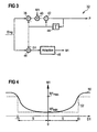
- the digital pulse filter 32 is shown that from the difference Elog of the current time window the pulse measure P generated.
- the pulse filter 32 contains two processing branches. In the first processing branch are connected in series first adder 38, a multiplier 40 and a second adder 42 included. The second adder 42 is followed by a delay element 44, the Output connected to the input of the first adder 38 is.
- the delay element 44 generates a signal delay T, which corresponds to the length of a time window.
- the digital filters work together a clock frequency of 8 kHz, so that the signal delay T and thus the length of a time window is set at 125 ns is.
- the second processing branch there is an adder 46 and an adapter 48 connected in series. The Input of adder 46 is also connected to the output of Delay element 44 connected.
- the first auxiliary variable D1 is formed by subtracting the pulse measure P delayed by T, ie the pulse measure P of the time window preceding the current time window, from the difference Elog of the current time window on the adder 28. If one designates the time window currently to be processed with n and the previous time window, ie a signal delay T previously processed, with n-1, then D1 can be written as (1) D1 (n) Elog (n) - P (n-1).
- the auxiliary variable D1 gives a measure of the change in the pulse measures P of two successive time windows. From the auxiliary variable D1 according to the relationship (1), the adaptation element 48 generates the adaptation variable M1 according to the characteristic curve 50 according to FIG. 4, which is supplied to the multiplication element 40. In the first processing branch, the pulse measure P (n-1) of the last processed time window n-1 is subtracted from the difference Elog (n) of the current time window n at the adder 38. The result of this subtraction is multiplied at the multiplication element 40 by the adaptation variable M1.
- the pulse measure P (n) of the time window n currently to be processed is the sum of two complementary weights Shares.
- the two shares are weighted using the Adaptation size M1, which generally has values between 0 and 1 can accept.
- the second part M1 dominates for large values of M1 ⁇ Elog (n), so that the pulse measure P (n) of the current time window n essentially by the difference Elog (n) of the current Time window n is given.
- the pulse measure P (n) remains for small values of D1 of the current time window n compared to the pulse measure P (n-1) of the previous frame n-1 almost unchanged since the first Adaptation function in this value range from D1 small values assumes close to 0.
- D1 increase the value of the adaptation size M1 too, so that the contribution of the difference Elog (n) des current time window n becomes larger and the pulse measure P (n) of the current time window n follows the difference Elog.
- the effect of the digital pulse filter 32 according to FIG. 3 is accordingly in that strong pulses over time the difference Elog can be detected while slight fluctuations in Elog to be smoothed.
- the first adaptation function with the characteristic curve 50 according to FIG. 4 can be approximated by a rectangular function which assumes a minimum value M1 min for magnitude values of D1 smaller than a predetermined amplitude value s and a maximum value M1 max for magnitude values of D1 greater than the predetermined amplitude value s.
- the predetermined amplitude value s is 10
- the minimum value M1 min is 1/32
- the maximum value M1 max is 1/2.
- the rectangular function is represented in FIG. 4 by a rectangular characteristic curve 52 (dashed line).
- the minimum value M1 min is shown exaggeratedly large in FIG. 4.
- the amplitude value s is set in such a way that the pulse measure P remains essentially unaffected by slight fluctuations in the difference Elog, but strong pulses of Elog are reflected in the course of P over time, which is illustrated later with reference to FIGS. 10 and 11.
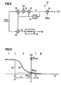
- the digital basic filter 34 is shown, the from the difference Elog (n) of the current time window n das Basic dimension G is generated.
- the basic filter 34 is essentially constructed in the same way as the Pulsf ter 14, so that on a detailed description of its structure at this point can be dispensed with.
- the components of the basic filter 34 which correspond to the components of the pulse filter 32 according to FIG. 2, are in Fig. 5 with the reference numerals of the components of the pulse filter 32.
- the digital basic filter 34 additionally contains a further adder 54, which on Output of the first processing branch is arranged. On the adder 54 becomes that of the adder 42 output basic dimension G and a predetermined threshold OF added and the result of this addition is output.
- the Adding the threshold value OF ensures a safety margin of the basic measure G compared to the pulse measure P.
- the Threshold value OF is set so that the safety distance is about 6 dB to 10 dB.
- the basic filter 34 also differs from the pulse filter 32 in that a second adaptation variable M2 which is different from the first adaptation variable M1 and which is supplied to the multiplication element 40 is determined in the adaptation element 48.
- the determination of the second adaptation variable M2 is based on a second adaptation function, the characteristic curve 56 of which is shown as a solid line in FIG. 6.
- the characteristic curve 56 falls from a higher level to a lower level near 0 within a transition region II, which predominantly contains negative values of D2.
- the second adaptation variable M2 determined according to the characteristic curve 56 becomes in the first Processing branch used to calculate the basic dimension G (n) of the current time window n.
- the basic dimension G (n-1) of the last processed time window n-1 is subtracted from the difference Elog (n) of the current time window n and the result of this subtraction is multiplied at the multiplication element 40 by the second adaptation variable M2.
- the result of this multiplication and the basic dimension G (n-1) of the last processed time window n-1 are added to the adder 42.
- Adaptation size M2 are weighted complementarily to each other.
- M2 can generally take values between 0 and 1. ever The larger M2 is, the less it bears due to the basic size G (n-1) of the previous time window n-1 given portion (1-M2) ⁇ G (n-1) to the basic dimension G (n) of the current time window n at. Conversely, as M2 decreases, the contribution M2 ⁇ Elog (n) reduced.
- equation (4) in connection with Fig. 6 the basic dimension G (n) for positive values of D2 (area III) essentially by the basic dimension G (n-1) of the previous one Time window n-1 given, since M2 for positive values of D2 Assumes values close to 0.
- the basic dimension G therefore remains at one sudden increase in difference Elog, i.e. on insertion the speech input during the announcement, essentially unchanged.
- D2 i.e. for bigger ones Values of M2
- I in FIG. 6 I denotes according to the equation (3) an area where the difference elog (n) versus the basic dimension G (n-1) drops significantly. This is the case as soon as the speech input is ended during the announcement.
- the second adaptation function can be approximated by a step function.
- a step-shaped characteristic curve 58 is shown in dashed lines in FIG. 6 as an approximation to the second adaptation function characterized by the characteristic curve 56.
- the adaptation variable M2 takes a maximum value M2 max in region I, which is given by values of D2 smaller than a predetermined negative value S1, in region II, which by values of D2 greater than or equal to the predetermined negative value S1 and less than or equal to a predetermined positive value S2, an intermediate value M2 zw and in the area III, which is given by values of D2 greater than the predetermined positive value S2, a minimum value M2 min .
- the second adaptation variable M2 is determined in accordance with the characteristic curve 58.
- the characteristic curve 58 is equal to -20 by S1, S2 equal to 10, M2 max is equal to 1/16, M2 zw equal to 1/128 and M2 characterized min is equal to 1/32768.
- the method of operation of the detector device 16 just explained 7 to 12 using the example of a concrete announcement and a concrete speech input illustrated.
- the voice input is the time of the announcement partially overlaid.
- 7 is the time course of the Announcement signal An, which corresponds to an announcement "Siemens", in shown in a time range from 0 to 1.8 s.
- the speech signal Sp is shown in FIG won by A-D conversion of a voice input "Mueller" has been.
- FIGS. 7 and 8 there is one partial temporal overlay of the announcement signal An and the Speech input signals Sp before.
- the echo path EP (see FIG. 1) is in this example by an over the entire frequency range largely constant attenuation of approx.
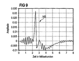
- the announcement signal On and the speech input signal Sp become after absolute value formation, logarithmization and averaging the signal difference Elog formed, their temporal Course is shown in Fig. 10.
- Fig. 10 Like a comparison of the Fig. 10 with Figs. 7 and 8 shows the signal difference Elog to great values at the times when the announcement signal On and overlay the voice input signal Sp. kick the announcement signal An, on the other hand, is the temporal Course of the signal difference Elog largely constant.
- the digital filters 32 and 34 generate from the signal difference Elog the pulse measure P and the basic measure in the manner described above G plus the predetermined threshold OF, whose temporal Course is shown in Fig. 11. At the times when if the announcement occurs alone, this is around the threshold OF Enlarged basic size, i.e.
- the threshold value OF is approximately 10 dB is set.
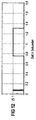
- the detector signal Dt with logic value 0 becomes voice input is output as shown in FIG.
- the occurrence of announcement and voice input exceeds the pulse measure P is the sum of the basic measure G and the threshold value OF, and the detector device 16 outputs the detector signal Dt with logic value 1, as also shown in FIG. 12 is.
- FIGS. 7, 8 and 12 show that the Detector device 16 a simultaneous occurrence of Announcement and voice input reliable and with negligible Delay detected.
Landscapes
- Engineering & Computer Science (AREA)
- Computational Linguistics (AREA)
- Health & Medical Sciences (AREA)
- Audiology, Speech & Language Pathology (AREA)
- Human Computer Interaction (AREA)
- Physics & Mathematics (AREA)
- Acoustics & Sound (AREA)
- Multimedia (AREA)
- Telephone Function (AREA)
- Measurement Of Mechanical Vibrations Or Ultrasonic Waves (AREA)
Claims (17)
- Procédé pour détecter une entrée de parole pendant une annonce vocale et destiné, notamment, à un système d'annonces vocales (10) contrôlé par la parole,
dans lequel on fait la moyenne, pendant une période de temps donnée, du signal numérique d'annonce vocale (An) et du signal d'entrée de parole (Sp),
on détermine, pour des fenêtres de temps de longueur donnée, des différences entre les signaux Elog entre la moyenne du signal d'entrée de parole (<Sp>) et la moyenne du signal d'annonce vocale (<An>),
les différences entre les signaux Elog de fenêtres de temps qui se succèdent, sont appliquées à un premier filtre numérique (32), lequel détermine, en tenant compte d'une première fonction d'adaptation (30) une mesure d'impulsion P, qui comprend, en plus d'une composante de base, une composante variable de la différence entre les signaux Elog,
les différences entre les signaux Elog de fenêtres de temps qui se succèdent, sont appliquées à un deuxième filtre numérique (34), lequel détermine, en tenant compte d'une deuxième fonction d'adaptation (56) une mesure de fond G, qui reproduit, pour l'essentiel, une composante de base de la différence entre les signaux Elog.
et dans lequel on génère un signal de détecteur (Dt) pour l'apparition simultanée de l'annonce vocale et de l'entrée de parole, lorsque la mesure d'impulsion P est supérieure à la mesure de fond G augmentée d'une valeur seuil donnée OF. - Procédé selon la revendication 1 caractérisé par le fait qu'on calcule la moyenne des valeurs absolues du signal de l'annonce vocale et du signal d'entrée de la parole.
- Procédé selon la revendication 1 ou 2 caractérisé par le fait qu'on calcule la moyenne des carrés des valeurs du signal de l'annonce vocale et du signal d'entrée de la parole.
- Procédé selon l'une des revendications 1 à 3 caractérisé par le fait qu'on utilise, comme différence entre les signaux Elog, la différence entre le logarithme de la moyenne du signal d'entrée de parole (<Sp>) et le logarithme de la moyenne du signal d'annonce vocale (<An>).
- Procédé selon l'une des revendications précédentes caractérisé par le fait que la différence entre les signaux Elog, qui est traitée par le premier filtre numérique (32), est appliquée à une première et à une deuxième branche de traitement du premier filtre numérique (32),
que la première branche de traitement a, montés en série, un premier élément additionneur (38), un élément multiplicateur (40) et un deuxième élément additionneur (42), qui délivre la mesure d'impulsion P,
que la mesure d'impulsion P est réinjectée avec un retard (T) d'au moins la longueur d'une fenêtre de temps et additionnée dans le deuxième élément additionneur (42) et soustraite dans le premier élément additionneur (38),
que la deuxième branche de traitement a, montés en série, un élément additionneur (46) et un élément d'adaptation (48),
que la mesure d'impulsion P retardée est soustraite dans l'élément additionneur (46) et, en tant que résultat, une première grandeur auxiliaire D1 est déterminée,
que, dans l'élément d'adaptation (48), on détermine, à partir de la première grandeur auxiliaire D1, une première grandeur d'adaptation M1 conformément à la première fonction d'adaptation donnée (50)
et que cette grandeur d'adaptation M1 est utilisée, dans la première branche de traitement, comme multiplicateur sur l'élément multiplicateur (40). - Procédé selon la revendication 5 caractérisé par le fait que la première fonction d'adaptation (50) définit une relation entre la première grandeur d'adaptation M1 et la première grandeur auxiliaire D1, qui est spécifiée par une courbe caractéristique en forme de cuve symétrique par rapport à l'axe zéro.
- Procédé selon la revendication 6 caractérisé par le fait que la première fonction d'adaptation est approchée par une fonction rectangulaire (52).
- Procédé selon la revendication 7 caractérisé par le fait que, pour des valeurs de la première grandeur auxiliaire D1 inférieures à une amplitude prédéterminée (s), la première grandeur d'adaptation M1 prend une valeur minimum (M1min) et, pour d'autres valeurs, une valeur maximum (M2max).
- Procédé selon la revendication 8 caractérisé par le fait que la valeur minimum (M1min) de la première grandeur d'adaptation M1 s'élève à environ 1/32 et la valeur maximum (M2max) à environ 1/2.
- Procédé selon l'une des revendications précédentes caractérisé par le fait que la différence entre les signaux Elog, qui est traitée par le deuxième filtre numérique (34), est appliquée à une première et à une deuxième branche de traitement du deuxième filtre numérique (34),
que la première branche de traitement a, montés en série, un premier élément additionneur (38), un élément multiplicateur (40), un deuxième élément additionneur (42) et un troisième élément additionneur (54), qui donne la mesure de fond G augmentée de la valeur seuil donnée OF,
que la mesure de fond G est réinjectée avec un retard (T) d'au moins la longueur d'une fenêtre de temps et additionnée dans le deuxième élément additionneur (42) et soustraite dans le premier élément additionneur (38),
que la deuxième branche de traitement a, montés en série, un élément additionneur (46) et un élément d'adaptation (48),
que la mesure de fond G retardée est soustraite dans l'élément additionneur (46) et, en tant que résultat, une deuxième grandeur auxiliaire D2 est déterminée,
que, dans l'élément d'adaptation (48), on détermine, à partir de la deuxième grandeur auxiliaire D2, une deuxième grandeur d'adaptation M2 conformément à la deuxième fonction d'adaptation donnée (56)
et que cette grandeur d'adaptation M2 est utilisée, dans la première branche de traitement, comme multiplicateur sur l'élément multiplicateur (40). - Procédé selon la revendication 10 caractérisé par le fait que la deuxième fonction d'adaptation (56) définit une relation entre la deuxième grandeur d'adaptation M2 et la deuxième grandeur auxiliaire D2, laquelle est spécifiée par une courbe caractéristique essentiellement en forme d'escalier qui, à l'intérieur d'une plage (II) de la deuxième grandeur auxiliaire D2, composée surtout de valeurs négatives, tombe d'un niveau élevé à un niveau plus faible.
- Procédé selon la revendication 11 caractérisé par le fait que la deuxième fonction d'adaptation (56) est approchée par une fonction en escalier (58).
- Procédé selon la revendication 12 caractérisé par le fait que la deuxième grandeur d'adaptation M2 prend, pour des valeurs de la grandeur auxiliaire D2 inférieures à une première valeur auxiliaire négative donnée (S1), une valeur minimum (M2min), pour des valeurs de la grandeur auxiliaire D2 supérieures ou égales à la première valeur auxiliaire (S1) et inférieures ou égales à une deuxième valeur auxiliaire positive donnée (S2), une valeur intermédiaire (M2zw) et, pour des valeurs de la grandeur auxiliaire D2 supérieures à la deuxième valeur auxiliaire (S2), une valeur maximum (M2max).
- Procédé selon l'une des revendications précédentes caractérisé par le fait que la valeur seuil OF se trouve entre 6 dB et 10 dB.
- Dispositif (16) destiné à exécuter le procédé selon l'une des revendications précédentes caractérisé par
un élément pour le calcul de la moyenne de l'annonce vocale (26), grâce auquel est calculée, sur une période de temps donnée, la moyenne du signal numérique d'annonce vocale (An),
un élément pour le calcul de la moyenne de l'entrée de parole (28), grâce auquel est calculée, sur une période de temps donnée, la moyenne du signal d'entrée de parole (Sp),
un élément additionneur (30), dont les entrées sont reliées à l'élément pour le calcul de la moyenne de l'annonce vocale (26) et à l'élément pour le calcul de la moyenne de l'entrée de parole (28) et qui détermine, pour des fenêtres de temps d'une longueur donnée, des différences entre signaux Elog, entre la moyenne du signal d'entrée de parole (<Sp>) et la moyenne du signal d'annonce vocale (<An>),
un premier filtre numérique (32), auquel sont appliquées les différences entre signaux Elog de fenêtres de temps qui se succèdent, et qui détermine, en tenant compte d'une première fonction d'adaptation (30), une mesure d'impulsion P, laquelle comporte, en plus d'une composante de base, une composante variable de la différence entre signaux Elog d'une fenêtre de temps,
un deuxième filtre numérique (34), auquel sont appliquées les différences entre signaux Elog de fenêtres de temps qui se succèdent, et qui détermine, en tenant compte d'une deuxième fonction d'adaptation (56), une mesure de fond G, qui reproduit, pour l'essentiel, une composante de base de la différence entre les signaux Elog d'une fenêtre de temps,
et une unité d'évaluation (36), qui génère un signal de détecteur (Dt) pour l'apparition simultanée de l'annonce vocale et de l'entrée de parole, lorsque la mesure d'impulsion P est supérieure à la mesure de fond G augmentée d'une valeur seuil donnée OF. - Dispositif (16) selon la revendication 15 caractérisé par le fait que le premier filtre numérique (32) a une première et une deuxième branche de traitement,
que la première branche de traitement a, montés en série, un premier élément additionneur (38), un élément multiplicateur (40) et un deuxième élément additionneur (42) et, en outre, derrière le deuxième élément additionneur (42), un élément temporisateur (44), dont la sortie est reliée à l'entrée du premier élément additionneur (38) et à l'entrée du deuxième élément additionneur (42) et
que la deuxième branche de traitement a, montés en série, un élément additionneur (46), dont l'entrée est reliée à la sortie de l'élément temporisateur (44), et un élément d'adaptation (48), dont la sortie est reliée à l'entrée de l'élément multiplicateur (40). - Dispositif (16) selon la revendication 15 ou 16 caractérisé par le fait que le deuxième filtre numérique (34) a une première et une deuxième branche de traitement,
que la première branche de traitement a, montés en série, un premier élément additionneur (38), un élément multiplicateur (40), un deuxième élément additionneur (42) et un troisième élément additionneur (54) et, en outre, un élément temporisateur (44), dont la sortie est reliée à l'entrée du premier élément additionneur (38) et à l'entrée du deuxième élément additionneur (42) et
que la deuxième branche de traitement a, montés en série, un élément additionneur (46), dont l'entrée est reliée à la sortie de l'élément temporisateur (44), et
un élément d'adaptation (48), dont la sortie est reliée à l'entrée de l'élément multiplicateur (40).
Applications Claiming Priority (2)
| Application Number | Priority Date | Filing Date | Title |
|---|---|---|---|
| DE19740221 | 1997-09-12 | ||
| DE19740221 | 1997-09-12 |
Publications (3)
| Publication Number | Publication Date |
|---|---|
| EP0902416A2 EP0902416A2 (fr) | 1999-03-17 |
| EP0902416A3 EP0902416A3 (fr) | 1999-10-27 |
| EP0902416B1 true EP0902416B1 (fr) | 2003-07-02 |
Family
ID=7842204
Family Applications (1)
| Application Number | Title | Priority Date | Filing Date |
|---|---|---|---|
| EP98114986A Expired - Lifetime EP0902416B1 (fr) | 1997-09-12 | 1998-08-11 | Procédé et dispositif pour reconnaitre une entrée de parole pendant la diffusion d'une annonce |
Country Status (2)
| Country | Link |
|---|---|
| EP (1) | EP0902416B1 (fr) |
| DE (1) | DE59808880D1 (fr) |
Families Citing this family (1)
| Publication number | Priority date | Publication date | Assignee | Title |
|---|---|---|---|---|
| EP1229518A1 (fr) * | 2001-01-31 | 2002-08-07 | Alcatel | Système, terminal, unité de système et procédé de reconnaissance de la parole |
Family Cites Families (5)
| Publication number | Priority date | Publication date | Assignee | Title |
|---|---|---|---|---|
| US4914692A (en) * | 1987-12-29 | 1990-04-03 | At&T Bell Laboratories | Automatic speech recognition using echo cancellation |
| US5125024A (en) * | 1990-03-28 | 1992-06-23 | At&T Bell Laboratories | Voice response unit |
| US5155760A (en) * | 1991-06-26 | 1992-10-13 | At&T Bell Laboratories | Voice messaging system with voice activated prompt interrupt |
| US5548681A (en) * | 1991-08-13 | 1996-08-20 | Kabushiki Kaisha Toshiba | Speech dialogue system for realizing improved communication between user and system |
| US5708704A (en) * | 1995-04-07 | 1998-01-13 | Texas Instruments Incorporated | Speech recognition method and system with improved voice-activated prompt interrupt capability |
-
1998
- 1998-08-11 EP EP98114986A patent/EP0902416B1/fr not_active Expired - Lifetime
- 1998-08-11 DE DE59808880T patent/DE59808880D1/de not_active Expired - Fee Related
Also Published As
| Publication number | Publication date |
|---|---|
| DE59808880D1 (de) | 2003-08-07 |
| EP0902416A2 (fr) | 1999-03-17 |
| EP0902416A3 (fr) | 1999-10-27 |
Similar Documents
| Publication | Publication Date | Title |
|---|---|---|
| EP0742664B1 (fr) | Méthode pour parler à main levée pour un système de transmission à canaux multiples | |
| EP0698986B1 (fr) | Procédé pour la compensation adaptative d'écho | |
| DE60108401T2 (de) | System zur erhöhung der sprachqualität | |
| DE69926851T2 (de) | Verfahren und Vorrichtung zur Sprachaktivitätsdetektion | |
| DE68919641T2 (de) | Halbduplex-Lautfernsprecher. | |
| DE69628411T2 (de) | Vorrichtung und Verfahren zur Geräuschreduzierung eines Sprachsignals | |
| DE2207141C3 (de) | Schaltungsanordnung zur Unterdrückung unerwünschter Sprachsignale mittels eines vorhersagenden Filters | |
| EP0747880B1 (fr) | Système de reconnaissance de la parole | |
| DE69627359T2 (de) | Verbesserter echokompensator mit anwendung in der digitalen telefonie | |
| EP1103956B1 (fr) | Réduction exponentielle de bruit et d'écho pendant les pauses de la parole | |
| DE68916219T2 (de) | Schallabgleichungsanordnung für einen sprachumschaltbaren Lautfernsprecher. | |
| DE10058786A1 (de) | Verfahren zum Steuerung eines eine akustische Ausgabeeinrichtung aufweisenden Geräts | |
| EP1155561B1 (fr) | Dispositif et procede de suppression de bruit dans des installations telephoniques | |
| DE69930109T2 (de) | Sprachgesteuerter schalter zur verwendung bei hohem umgebungsgeräusch | |
| DE3422877A1 (de) | Verfahren und vorrichtung zum ermitteln der endpunkte von sprachsignalen | |
| EP0459563B1 (fr) | Système de commutation avec un dispositif de conférence | |
| EP0600164A1 (fr) | Procédé pour l'amélioration de la qualité de transmission d'un dispositif électro-acoustique | |
| DE3329779C2 (de) | Verfahren und Schaltungsanordnung zur Herstellung von Konferenzverbindungen in einem Vermittlungssystem | |
| DE10137348A1 (de) | Verfahren und Schaltungsanordnung zur Geräuschreduktion bei der Sprachübertragung in Kommunikationssystemen | |
| EP1005016A2 (fr) | Procédé et dispositif de circuit pour mesurer le niveau de parole dans un système de traitement du signal de parole | |
| EP0902416A2 (fr) | Procédé et dispositif pour reconnaitre une entrée de parole pendant la diffusion d'une annonce | |
| EP0902414B1 (fr) | Système et méthode de commande d'un système de diffusion d'annonces | |
| EP1168801A2 (fr) | Annulation d'écho adaptatif en fonction du bruit | |
| EP1104096A2 (fr) | Suppression de bruit adaptée au niveau du bruit actuel | |
| DE19753224C2 (de) | Verfahren und Vorrichtung zur Echounterdrückung bei einer Freisprecheinrichtung, insbesondere für ein Telefon |
Legal Events
| Date | Code | Title | Description |
|---|---|---|---|
| PUAI | Public reference made under article 153(3) epc to a published international application that has entered the european phase |
Free format text: ORIGINAL CODE: 0009012 |
|
| AK | Designated contracting states |
Kind code of ref document: A2 Designated state(s): DE FR GB IT |
|
| AX | Request for extension of the european patent |
Free format text: AL;LT;LV;MK;RO;SI |
|
| PUAL | Search report despatched |
Free format text: ORIGINAL CODE: 0009013 |
|
| AK | Designated contracting states |
Kind code of ref document: A3 Designated state(s): AT BE CH CY DE DK ES FI FR GB GR IE IT LI LU MC NL PT SE |
|
| AX | Request for extension of the european patent |
Free format text: AL;LT;LV;MK;RO;SI |
|
| 17P | Request for examination filed |
Effective date: 19991118 |
|
| AKX | Designation fees paid |
Free format text: DE FR GB IT |
|
| GRAH | Despatch of communication of intention to grant a patent |
Free format text: ORIGINAL CODE: EPIDOS IGRA |
|
| RIC1 | Information provided on ipc code assigned before grant |
Free format text: 7G 10L 15/20 A |
|
| GRAH | Despatch of communication of intention to grant a patent |
Free format text: ORIGINAL CODE: EPIDOS IGRA |
|
| GRAA | (expected) grant |
Free format text: ORIGINAL CODE: 0009210 |
|
| AK | Designated contracting states |
Designated state(s): DE FR GB IT |
|
| REG | Reference to a national code |
Ref country code: GB Ref legal event code: FG4D Free format text: NOT ENGLISH |
|
| REF | Corresponds to: |
Ref document number: 59808880 Country of ref document: DE Date of ref document: 20030807 Kind code of ref document: P |
|
| GBT | Gb: translation of ep patent filed (gb section 77(6)(a)/1977) |
Effective date: 20031023 |
|
| PLBE | No opposition filed within time limit |
Free format text: ORIGINAL CODE: 0009261 |
|
| STAA | Information on the status of an ep patent application or granted ep patent |
Free format text: STATUS: NO OPPOSITION FILED WITHIN TIME LIMIT |
|
| ET | Fr: translation filed | ||
| 26N | No opposition filed |
Effective date: 20040405 |
|
| PGFP | Annual fee paid to national office [announced via postgrant information from national office to epo] |
Ref country code: DE Payment date: 20051021 Year of fee payment: 8 |
|
| PGFP | Annual fee paid to national office [announced via postgrant information from national office to epo] |
Ref country code: GB Payment date: 20060808 Year of fee payment: 9 |
|
| PGFP | Annual fee paid to national office [announced via postgrant information from national office to epo] |
Ref country code: FR Payment date: 20060809 Year of fee payment: 9 |
|
| PGFP | Annual fee paid to national office [announced via postgrant information from national office to epo] |
Ref country code: IT Payment date: 20060831 Year of fee payment: 9 |
|
| PG25 | Lapsed in a contracting state [announced via postgrant information from national office to epo] |
Ref country code: DE Free format text: LAPSE BECAUSE OF NON-PAYMENT OF DUE FEES Effective date: 20070301 |
|
| GBPC | Gb: european patent ceased through non-payment of renewal fee |
Effective date: 20070811 |
|
| REG | Reference to a national code |
Ref country code: FR Ref legal event code: ST Effective date: 20080430 |
|
| PG25 | Lapsed in a contracting state [announced via postgrant information from national office to epo] |
Ref country code: FR Free format text: LAPSE BECAUSE OF NON-PAYMENT OF DUE FEES Effective date: 20070831 |
|
| PG25 | Lapsed in a contracting state [announced via postgrant information from national office to epo] |
Ref country code: GB Free format text: LAPSE BECAUSE OF NON-PAYMENT OF DUE FEES Effective date: 20070811 |
|
| PG25 | Lapsed in a contracting state [announced via postgrant information from national office to epo] |
Ref country code: IT Free format text: LAPSE BECAUSE OF NON-PAYMENT OF DUE FEES Effective date: 20070811 |